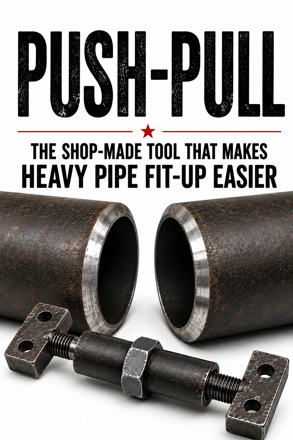
Some of the most useful tools in pipefitting aren’t tools you can simply walk into a supply house and buy. They are created in fabrication shops, tool rooms, pipe racks, and industrial jobsites because experienced fitters encounter a problem and fabricate something that solves it.
The push-pull tool is one of those tools. A pipefitter’s push-pull is a temporary mechanical fit-up tool used to make small, controlled adjustments between two sections of pipe during fabrication or installation. Depending on how the tool is built and positioned, it can help pull two pieces of pipe together or push them apart so the fitter can establish the required root gap and improve the overall fit before tack welding.
Push-pulls are particularly useful when working with large-diameter pipe, where even moving a pipe a fraction of an inch can require considerable force. They can be especially useful on pipe racks, large fabrication assemblies, refinery piping, power plants, petrochemical facilities, pipeline facilities, and other heavy industrial piping systems.
The push-pull belongs to the same family of practical shop-made pipefitting tools as the dog, doghouse, strongback, wedge, bridge, and other temporary fit-up devices that generations of fitters have fabricated for specific jobs.
For more practical industrial and skilled-trades information, visit the Næxon Resources section.
What Is a Pipefitter Push-Pull?
At its simplest, a push-pull is a mechanical adjuster positioned between two temporary attachment points near a pipe fit-up.
Those attachment points are often called dogs.
The tool contains some form of threaded or mechanical adjustment. Turning the adjustment changes the effective length of the push-pull.
Depending on the design, shortening the tool can pull the attachment points toward one another, while extending it can push them apart.
That movement is transferred through the dogs to the pipe.
Instead of trying to physically muscle a heavy piece of pipe into position, the fitter uses mechanical advantage to make very small, controlled corrections.
This is important because a push-pull is generally not intended to move an entire spool from one location to another. Rigging equipment, cranes, chain falls, come-alongs, jacks, and other approved positioning equipment handle the major movement.
The push-pull becomes useful when the pipe is already supported and very close to its final position, but the fitter needs that last little adjustment to get the fit where it needs to be.
Why Pipefitters Use Push-Pulls
Anyone who has fitted large pipe knows that being close isn’t necessarily good enough.
Two pipe ends can look almost perfectly aligned, yet the root opening may be too wide on one side and too tight on another. One spool may need to move slightly toward the joint. Another may need to move away.
With smaller pipe, the fitter may sometimes be able to make these corrections using relatively simple methods. Large-bore piping changes everything.
A piece of large-diameter, heavy-wall pipe can weigh thousands of pounds. Even though the fitter may only need to move it a tiny amount, that small movement can require considerable force.
That’s where the push-pull becomes extremely useful. Rather than trying to force the pipe into position suddenly, the threaded mechanism allows the fitter to apply force gradually.
Turn the adjustment slightly. Check the gap. Turn it again. Measure again. The result is controlled movement instead of brute force.
The Push-Pull Is a Fine-Adjustment Tool
One of the most important things to understand about the push-pull is what it is not.
A shop-fabricated push-pull should not automatically be considered a lifting device, hoist, pipe support, or rated rigging component.
Its primary purpose is fine adjustment during pipe fit-up after the piping has already been properly supported.
This distinction becomes especially important with homemade tools.
A fabricated push-pull may contain threaded rods, nuts, pipe, plate, dogs, welds, or even modified commercial components. The strength of one component does not establish the safe capacity of the completed tool.
Any fabricated push-pull should therefore be built, inspected, attached, and used according to the employer’s fabrication procedures, temporary-attachment requirements, engineering requirements, welding procedures, and site rules.
Where Push-Pulls Are Commonly Used
One of the best examples is a pipe rack.
Imagine a large spool being lowered between two existing sections of piping. The rigging crew gets the spool extremely close to its final position.
Now the fitter takes over.
Elevation is checked.
Centerline is checked.
Orientation is checked.
The fit-up is checked.
Everything may be close, but one section of the joint still needs a slight adjustment.
The fitter doesn’t necessarily want the entire spool picked back up and repositioned for a tiny correction.
With the pipe properly supported, an approved push-pull arrangement can sometimes provide exactly the small amount of movement necessary.
Push-pulls may be encountered during:
- Large-bore pipe-rack fit-ups
- Refinery piping installation
- Petrochemical construction
- Power plant construction and maintenance
- Industrial fabrication
- Pipeline facilities and terminals
- Shutdown and turnaround work
- Heavy industrial maintenance
These are also environments where proper PPE and workwear matter. Næxon covers many of those conditions in the Ultimate Guide to Industrial Workwear.
How a Push-Pull Controls the Root Gap
Consider two beveled pipe ends positioned almost perfectly together.
The fitter checks the root opening around the circumference.
Suppose the gap is slightly too wide in the area being adjusted.
A push-pull configured to pull can apply controlled force that brings the two attachment points closer together.
The pipe moves slightly.
The fitter checks the gap again.
If necessary, another small adjustment is made.
Then the joint is checked again.
The important word is controlled.
A push-pull isn’t supposed to be cranked as hard as possible until something moves. It should be used to make small corrections while the fitter continuously monitors the joint.
The same principle works in the opposite direction.
If the fit is too tight, a push-pull designed to work in compression can create a controlled pushing action, moving the attachment points farther apart.
That’s where the name comes from.
It can push.
It can pull.
Push-Pulls Can Also Help With Alignment
Root opening is one of the primary reasons for using a push-pull, but the tool can also be part of a larger strategy for improving alignment.
Experienced fitters may use combinations of dogs, wedges, bridge clamps, strongbacks, chain falls, come-alongs, jacks, clamps, push-pulls, and other approved fit-up equipment depending on the particular joint.
The objective is always the same:
Put the pipe where the drawing, specification, and welding procedure require it to be before it becomes permanently welded.
The push-pull simply gives the fitter another way of applying controlled force exactly where it is needed.
Three Ways a Pipefitter Push-Pull Can Be Fabricated
There is no single universal push-pull design.
Different fabrication shops and crews develop different versions depending on the type and size of piping they normally work with.
Three practical designs are especially useful to understand.
Version 1: Plate-and-Bolt Push-Pull
The first version is the traditional compact fabricated push-pull.
A heavy steel plate or fabricated body provides the structural reaction point. A threaded bolt or rod passes through or works against part of the body. A nut or welded threaded section provides the mechanical adjustment.
Temporary dogs provide the attachment points near the pipe fit.
Turning the threaded adjustment changes the position of the tool and transfers force into the dogs.
The advantage of this design is simplicity.
There are relatively few moving parts, and the threaded mechanism allows the fitter to make extremely small adjustments.
Another advantage is its compact size.
Pipe racks can become extremely crowded. There may be structural steel, neighboring pipes, valves, supports, insulation, cable trays, and other equipment surrounding the fit.
A compact push-pull can sometimes fit where a larger come-along or other device cannot.
Version 2: Modified Ratchet Chain-Binder Push-Pull
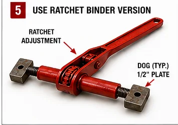
Another practical version can be created around the operating principle of a ratchet-style chain load binder.
Chain binders are commonly carried on semi-trucks, equipment trailers, and industrial transportation equipment because they’re designed to mechanically tension chain during cargo securement.
The mechanism already contains something useful to a pipefitter: a heavy threaded system that can shorten or lengthen the assembly through controlled ratcheting.
For a dedicated shop-made fit-up tool, a similar ratcheting mechanism can be fitted with purpose-made dogs or attachment ends instead of conventional chain hooks, provided the modification is approved for the intended application.
The dogs provide connection points for the pipe fit-up. Operating the ratchet changes the effective length of the tool. Shortening the assembly creates a pulling action.
A properly designed arrangement capable of operating in compression can provide a pushing action as well. This version provides excellent mechanical advantage and can be particularly useful on large-bore piping where even a small movement requires significant force.
Important Warning About Modified Chain Binders
Once a commercially manufactured load binder has been cut, welded, altered, or fitted with homemade attachments, do not assume the manufacturer’s original working-load rating still applies.
The modified assembly has effectively become a fabricated fit-up tool.
Its capacity depends on the entire assembly, including the dogs, modifications, threaded components, welds, geometry, and attachment method.
A modified push-pull should never automatically be treated as an approved lifting, rigging, or cargo-securement device simply because the original component was a rated chain binder.
Version 3: Pipe-Body and Threaded-Rod Push-Pull
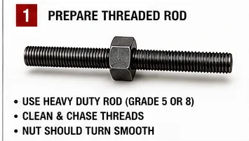
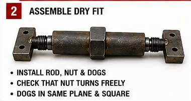
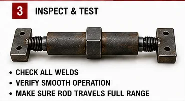
The third version may be the simplest concept for a fabrication shop to understand.
The main body consists of an appropriately selected piece of small-diameter pipe or tubular steel.
A long threaded rod or threaded bolt forms the mechanical adjustment.
A nut, coupling, or fabricated threaded section provides the means of changing the effective length of the tool.
Dogs are incorporated at the ends.
The basic concept looks like this:
DOG — THREADED ADJUSTMENT — PIPE BODY — THREADED ADJUSTMENT — DOG
Turning the adjustment changes the distance between the two dogs.
Depending on the thread arrangement and construction, the tool can be configured to pull the attachment points together or push them farther apart.
A more sophisticated version can use opposing threads—one right-hand and one left-hand—so turning the center section causes both ends to move simultaneously.
That works on the same basic mechanical principle as a turnbuckle.
The exact pipe size, wall thickness, threaded-rod diameter, dog dimensions, material grade, weld size, and overall length should be selected according to the expected fit-up forces and the employer’s fabrication requirements rather than copied blindly from another homemade tool.
How to Fabricate a Basic Pipe-Body Push-Pull
The pipe-body version is a good example for understanding the fabrication process because the principle is relatively straightforward.
Before fabrication begins, determine exactly what the tool is expected to accomplish.
A small push-pull intended for minor fit-up correction is not necessarily appropriate for large, heavy-wall pipe.
Components shouldn’t be selected simply because they happen to be lying in a scrap bin.
The body, threaded components, dogs, attachment points, and welds all work together as one mechanical system.
Step 1: Determine the Adjustment Design
First decide how the tool will change length.
A simple design can use a threaded rod moving through a fixed threaded section.
Another design can use opposing right-hand and left-hand threads, creating a turnbuckle-style arrangement.
The opposing-thread design can provide excellent control because turning the center section moves both ends simultaneously.
Regardless of the design, adequate thread engagement must remain throughout the intended working range.
A tool should never be extended so far that only a few threads remain engaged.
Step 2: Select the Body Material
Choose appropriately sized pipe or tubular steel for the main body.
The body must remain straight while the tool is loaded.
Cut the ends square and clean the material before fabrication.
Remove burrs, slag, scale, oil, and contamination from areas that will be welded.
Remember that simply using thicker pipe doesn’t automatically make the completed tool stronger.
The tool is a system.
The threaded rod, nuts, dogs, welds, attachment geometry, and body all contribute to its strength.
The weakest part of that system can determine how the tool fails.
Step 3: Prepare the Threaded Components
The threaded mechanism is the heart of the push-pull.
Threads should be clean and undamaged.
Avoid threaded rods or bolts that are heavily worn, stretched, mushroomed, bent, badly corroded, or of unknown condition.
The threaded components should operate smoothly through the intended adjustment range.
Threads that bind badly without a load are unlikely to improve once substantial force is applied.
Step 4: Fabricate the Dogs
The dogs transfer force from the push-pull into the temporary pipe attachment.
Their shape should allow the push-pull to connect securely while keeping the force reasonably close to the centerline of the tool.
This is important.
A push-pull generally works best when force travels straight through its body.
If the dogs position the tool at a severe angle, additional bending forces can be introduced into components primarily intended to work in tension or compression.
Step 5: Fit the End Components
Before completing the welds, fit the components together and check alignment.
Both ends should line up as closely as practical with the centerline of the body.
Tack everything first.
Check it.
Then check it again.
Once the geometry is correct, complete the welds according to the approved fabrication procedure.
A shop-made industrial tool doesn’t need beautiful cosmetic welds.
It needs sound welds and correct geometry.
Step 6: Install the Adjustment Mechanism
The adjusting nut or operating section should remain accessible when the tool is installed.
The fitter needs enough room to operate the adjustment without placing hands directly between pieces of pipe or inside another pinch point.
If a nut or threaded coupling is welded into the body, welding distortion should also be considered.
Excessive heat around threaded components can distort the threads and cause the mechanism to bind.
After welding, run the threaded mechanism through its complete intended travel and verify smooth operation.
Step 7: Clean and Inspect the Tool
Before putting the fabricated push-pull into service, inspect the entire assembly.
Pay particular attention to:
- Weld condition
- Thread condition
- Dog attachment points
- Straightness
- Cracks
- Distortion
- Thread engagement
- Bent or mushroomed components
Operate the tool through its intended range without load.
Any serious problem should be corrected before the tool is used.
Step 8: Identify Fabricated Tooling
In a well-organized fabrication shop, homemade tooling shouldn’t simply become an anonymous piece of steel thrown into a gang box.
Where company procedures require it, fabricated tooling can be marked, tagged, tracked, or inspected so workers know its intended purpose and limitations.
Never invent an unofficial load rating for a homemade push-pull.
If a fabricated tool has been engineered or proof-tested for a particular application, its identification should preserve that information.
How a Push-Pull Is Used During an Actual Pipe Fit
Picture a large horizontal pipe rack.
One section of pipe is already installed.
A new spool is rigged into position and properly supported.
The fitter checks elevation, centerline, orientation, flange position, dimensions, and the joint itself.
The bevels are close.
But the root opening is slightly wider than required in one area.
Following the project’s approved temporary-attachment procedure, dogs are positioned so the push-pull can work across the area requiring adjustment.
The tool is installed.
The fitter makes a small adjustment.
Then the fit is measured again.
Another small adjustment may follow.
Then another measurement.
The process should look something like:
Adjust → Measure → Recheck → Adjust Again
Not:
Crank until something moves.
A skilled fitter uses a push-pull as a precision adjustment tool, not simply as a source of brute force.
Don’t Fight the Rigging With a Push-Pull
A push-pull isn’t intended to compensate for badly positioned or improperly supported pipe.
If the spool is substantially out of position, correct the rigging, supports, crane position, chain fall, come-along, jack, or other positioning arrangement first.
Trying to force a seriously misaligned spool into position using temporary dogs and a small fabricated tool can create tremendous stored energy.
It can also transfer unwanted loads into pipe supports, structural members, equipment nozzles, flanges, existing welds, or connected equipment.
Get the pipe close with proper positioning equipment first.
Then use the push-pull for the fine adjustment.
Stored Energy and Line-of-Fire Hazards
Whenever steel is being mechanically forced into another position, energy is being stored.
The pipe may want to return toward its original position.
A threaded tool under tension wants to shorten.
A tool under compression can buckle or kick sideways.
A dog can fail.
A weld can fail.
Threads can strip.
A component can fracture.
That means workers should stay out of the potential line of fire.
Hands, fingers, faces, and bodies shouldn’t be positioned where they could be struck or trapped if the tool, attachment, or pipe suddenly releases.
Industrial workers performing this type of work should also wear the PPE required for the facility and task. For more information about those environments, see Næxon’s guide to What to Wear During Refinery Turnarounds and Maintenance Outages.
Temporary Dogs Must Be Controlled
Welding temporary dogs directly to process piping isn’t automatically acceptable simply because it has traditionally been done in the trade.
Different owners, materials, piping classes, services, specifications, and projects have different requirements.
Some piping systems tightly control temporary attachments.
Certain applications may prohibit them entirely.
When temporary attachments are permitted, procedures may establish requirements for the attachment material, welding procedure, welder qualification, preheat, permitted locations, removal method, grinding, surface restoration, inspection, and NDE.
Always follow the governing project requirements.
Removing the Dogs After Fit-Up
Once the joint has been securely tacked or otherwise restrained according to the approved fit-up procedure, the force on the push-pull can be gradually released.
The tool can then be removed.
Temporary dogs should be removed according to the approved procedure.
They should not automatically be knocked off simply because the fit is finished.
Improper removal can tear material from the pipe surface.
Depending on the piping specification, the attachment area may need controlled grinding, blending, visual examination, or additional NDE after removal.
The objective is to restore the pipe surface to the condition required by the governing specification.
Fabricating a Push-Pull for Stainless Steel Work
Stainless piping introduces another consideration: contamination.
Carbon-steel tools contacting stainless material can transfer free iron particles onto the stainless surface. Those particles can later rust and create contamination or corrosion concerns.
For dedicated stainless work, a shop may fabricate the contact components—or potentially the entire push-pull—from appropriate stainless material when required by the project.
Dedicated stainless fabrication tools should also remain separated from carbon-steel tools where contamination control is required.
The same principle applies to wire brushes, grinding wheels, flap discs, files, and similar equipment.
A tool used extensively on carbon steel should not automatically be used on stainless.
If temporary dogs are attached to stainless piping, the dog material, filler metal, welding procedure, removal method, and surface restoration should comply with the project’s requirements.
Depending on the application, stainless work can also involve additional requirements involving heat input, surface restoration, pickling, passivation, NDE, and contamination control.
Why Root Gap Matters
The push-pull ultimately exists because fit-up matters.
A welder can compensate for many minor difficulties, but the fitter’s job is to give the welder the best joint possible.
Correct root opening, proper internal alignment, clean bevels, correct dimensions, and a stable joint make welding more predictable.
The push-pull helps establish those conditions before the arc is struck.
The fitter isn’t simply connecting one pipe to another.
The fitter is controlling the geometry that determines whether the finished piping system matches the drawing and whether the welder receives a joint that can be welded according to procedure.
Workers involved in this type of hot work should also understand proper protective clothing. Næxon covers this subject further in What Every Welder Should Know About Flame-Resistant Apparel.
Why Experienced Pipefitters Fabricate Their Own Tools
There is a reason tools such as dogs, doghouses, strongbacks, wedges, bridges, push-pulls, homemade flange aids, and specialty alignment fixtures have survived generation after generation.
Commercial manufacturers cannot possibly build a specialized tool for every unusual condition encountered inside an industrial facility.
Pipe racks are crowded.
Clearances are tight.
Spools are heavy.
Existing piping isn’t always conveniently positioned.
Sometimes the tool that solves the problem is something a fitter and welder fabricate in the shop that morning.
That doesn’t excuse unsafe fabrication.
Instead, it demonstrates one of the defining characteristics of the skilled trades: understanding mechanical principles well enough to develop a practical solution to a difficult field problem.
Many of these homemade tools and techniques eventually become part of the language of the trade. Næxon explores more of that culture in The Language of the Blue Collar: 250 Funny Words, Phrases & Jobsite Lingo.
The Best Push-Pull Is Usually the Simplest One That Works
There is no reason to make a push-pull unnecessarily complicated.
For some applications, the compact plate-and-bolt version may be ideal.
For another job, a ratcheting mechanism may provide the necessary range and mechanical advantage.
For everyday fabrication, the small pipe-body and threaded-rod design may be the most practical.
Whatever design is used, a good push-pull should provide controlled adjustment, fit the available workspace, remain aligned while loaded, use appropriate materials, allow operation without unnecessarily exposing the fitter to pinch points, and comply with the employer’s requirements.
Complexity doesn’t automatically make a better tool.
Control does.
Never Use an Unknown Homemade Push-Pull Blindly
If you find a homemade push-pull sitting in an old gang box, don’t automatically assume it is ready to use.
You may not know what material the threaded rod was made from.
You may not know who welded it.
You may not know whether it has previously been overloaded.
You may not know whether someone heated and bent it.
You may not know whether a crack is hiding beneath old paint or slag.
Fabricated tooling should be inspected before use.
If there is doubt about its condition or suitability, it should be removed from service until it can be properly evaluated.
A shortcut isn’t worth an uncontrolled release of stored mechanical energy.
A Small Tool That Can Solve a Big Fit-Up Problem
The pipefitter’s push-pull is a perfect example of practical field engineering.
Its job sounds remarkably simple:
Move the fit a little.
Anyone who has fitted large pipe, however, knows exactly how valuable that little movement can be.
When a heavy spool is already positioned on a pipe rack and the root opening needs only a slight correction, moving the entire assembly can be difficult and inefficient.
A properly designed push-pull allows the fitter to convert the rotation of a threaded or ratcheting mechanism into controlled linear movement exactly where the correction is needed.
Sometimes that means pulling the fit tighter.
Sometimes it means pushing the fit apart.
Either way, the fitter gains control.
Whether the push-pull is fabricated from a plate and threaded bolt, built around a modified ratcheting mechanism, or made using a simple pipe body with threaded adjustment and dogs, the basic principle remains the same:
Mechanical advantage replaces brute force.
Like the dog and doghouse, the push-pull demonstrates why pipefitting is much more than measuring pipe and assembling fittings.
The trade requires an understanding of geometry, welding, rigging, mechanical forces, materials, fabrication, sequencing, and sometimes the ability to fabricate the exact tool necessary to finish the job.
The push-pull may never be the most expensive tool in the gang box.
It may not even have a manufacturer’s name stamped on it.
But when a large-bore fit is sitting on the rack and the gap needs just a little movement, it can become one of the most useful tools on the job.
That’s the kind of practical field knowledge that gets passed from fitter to fitter, crew to crew, and generation to generation—and it’s worth preserving.