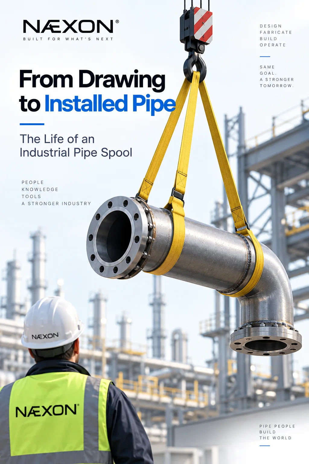
A finished pipe spool hanging between two pieces of equipment can look deceptively simple.
A few feet of pipe. Maybe an elbow, a reducer, a flange, and a couple of welds.
But before that spool ever reaches its final position, it may pass through engineering, detailing, material control, fabrication, inspection, coating, transportation, rigging, fit-up, welding, testing, and final turnover.
By the time a pipefitter bolts the last flange and the line becomes part of an operating system, dozens of decisions may already have been made.
Understanding that journey is useful for more than engineers and project managers. It helps pipefitters, welders, foremen, fabricators, inspectors, and apprentices understand why certain dimensions matter—and why a seemingly small mistake early in the process can become a major field problem later.
It Starts With the Piping Design
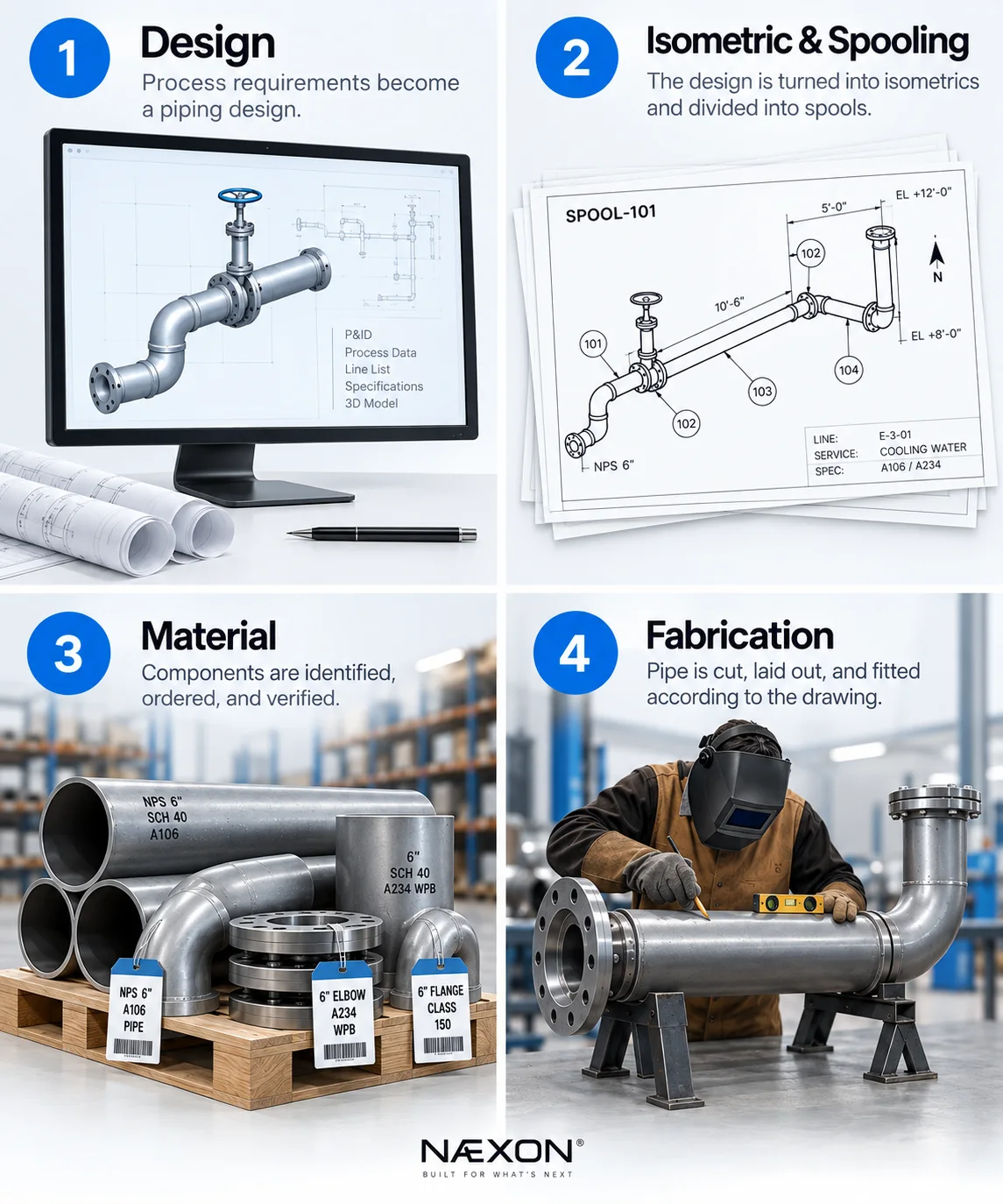
Figure 1. The first four stages of an industrial pipe spool: piping design, isometric and spool development, material identification and verification, and fabrication according to the drawing.
Long before steel is cut, the piping system exists as engineering information.
Process requirements establish what the line must accomplish. Engineers determine things such as operating pressure, temperature, material requirements, pipe size, wall thickness, valves, equipment connections, and routing.
The piping design eventually provides the information needed to create fabrication and installation drawings.
One of the most important documents for the pipe trade is the piping isometric.
An isometric takes a three-dimensional piping arrangement and represents it on a two-dimensional drawing. It can show pipe sizes, dimensions, elevations, fittings, valves, flanges, welds, branches, reducers, supports, equipment connections, and other information necessary to fabricate and install the system.
For a pipefitter, learning to interpret that information correctly is one of the most valuable skills in the trade.
The Isometric Becomes Fabrication Information
A large piping system usually isn’t fabricated as one enormous assembly.
It is divided into manageable sections called spools.
A spool might contain a straight piece of pipe with two flanges. Another could contain multiple elbows, branches, reducers, and connections.
Where those spool breaks occur matters.
The assembly has to be practical to fabricate, transport, rig, and install.
A spool that looks perfectly reasonable on a drawing can become a nightmare if nobody considers how it will physically enter the structure.
Experienced fabrication and construction teams therefore think beyond dimensions.
They think about installation.
Can a crane reach it?
Will it pass through the structural steel?
Can the crew rotate it into position?
Is there enough room to make the field weld?
Can the bolts actually be installed?
Can the gasket be inserted?
These questions can determine whether a spool installs smoothly or becomes a field modification.
Material Has to Match the Drawing
Once the spool is released for fabrication, the required material must be identified and controlled.
Depending on the system, that can include pipe, elbows, tees, reducers, flanges, branch fittings, valves, gaskets, bolts, specialty components, and other items.
But identifying a component by size alone isn’t enough.
Industrial piping may require specific schedules, pressure classes, materials, specifications, flange facings, fitting types, and other characteristics.
A 6-inch flange isn’t simply a 6-inch flange.
Its pressure class, facing, material, bore, bolt pattern, and specification can determine whether it belongs in that particular system.
The same principle applies to pipe.
Nominal pipe size does not directly describe the pipe’s outside diameter, and different schedules can produce different wall thicknesses and inside diameters.
NÆXON’s In-dex piping reference system is being developed around this exact type of field information—giving tradespeople a faster way to reference pipe, fittings, flanges, dimensions, wall thicknesses, bolt patterns, takeoffs, and related component data.
The Fabricator Turns Dimensions Into Steel
Now the spool begins becoming physical.
Pipe is measured and cut according to the fabrication dimensions.
But the cut length is rarely just the dimension printed between two points on the drawing.
Fitting takeoffs must be considered.
Weld gaps may need to be considered.
Flange dimensions matter.
Elbow geometry matters.
Branch locations matter.
Orientation matters.
This is where pipefitting mathematics becomes extremely important.
Consider a simple run containing two elbows.
The overall dimension may be known, but the fitter must subtract the appropriate fitting takeoffs to determine the actual pipe cut length.
More complicated assemblies can involve offsets, rolling offsets, odd-degree fittings, slopes, multiple branches, or changing elevations.
NÆXON’s Numerus was developed specifically around these kinds of pipe-trade calculations, including offsets, fitting geometry, spool calculations, layout, conversions, and other field mathematics.
The calculation is only one part of the job.
The fitter still has to turn that number into an accurate piece of pipe.
Layout Determines Whether Everything Lines Up
Before welding, the spool must be laid out correctly.
Flange orientation may have to match equipment or another spool.
Branches must point in the correct direction.
Reducers must be oriented properly.
Elbows must be rolled correctly.
Valve operators may require specific accessibility.
Even when every individual dimension is correct, incorrect orientation can make the entire spool unusable.
This is why experienced fitters don’t simply check length.
They check relationships.
Where is north?
Where is the top of pipe?
Which direction does the branch face?
Where are the flange bolt holes?
What elevation does the centerline reach?
What does the next spool connect to?
The spool has to work as part of a larger system.
Tack-Up Locks the Geometry Together
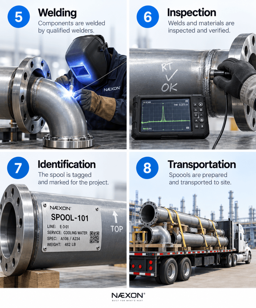
Figure 2. The next four stages of an industrial pipe spool: welding, inspection and verification, spool identification and tagging, and transportation to the project site.
Once the components are positioned, they are fitted and tacked.
This stage deserves more attention than it sometimes receives.
A poor fit-up can create problems that welding cannot magically correct.
The fitter may check root opening, alignment, high-low, squareness, dimensions, orientation, flange rotation, branch location, and overall spool geometry before releasing the assembly for welding.
A common field principle applies here:
Check it before you weld it.
Moving a tack is usually easier than cutting apart a completed weld.
Welding Can Change the Spool
After fit-up, the welder completes the required joints according to the applicable welding procedure.
But welding introduces heat.
Heat can introduce movement.
Long or complicated spools can distort during welding if sequence, restraint, fit-up, and heat input are not properly considered.
That means a spool that measured perfectly during initial layout may need to be checked again after welding.
Critical dimensions and flange orientations may be verified before the spool moves to the next stage.
This is one reason good fabrication is a partnership between fitter and welder rather than two completely separate operations.
Inspection Verifies the Work
Depending on the service and project requirements, completed welds may undergo visual inspection and additional nondestructive examination.
Methods can include radiographic testing, ultrasonic testing, magnetic particle testing, liquid penetrant testing, or other examination methods depending on the material, weld type, code, and specification.
Material identification and traceability may also be required.
The purpose isn’t simply to make the spool look good.
The completed piping system may eventually contain hydrocarbons, steam, chemicals, compressed gases, high-temperature fluids, or other hazardous process media.
Integrity matters.
The Spool Gets Identified
On a major industrial project, hundreds or thousands of fabricated spools may exist simultaneously.
Without identification, the laydown yard would quickly become chaos.
Spools are typically marked according to project identification systems so crews can connect the physical assembly to the correct drawing and line.
That identification becomes extremely important once fabrication leaves the shop.
A pipefitter in the field needs to know exactly which piece belongs where.
Then Comes Transportation
Fabricated spools may travel across a fabrication shop, across a project site, or hundreds of miles from an off-site fabrication facility.
Transportation creates another design constraint.
Extremely large or awkward assemblies may be difficult or expensive to ship.
Flange faces may require protection.
Small branches can be vulnerable to damage.
Temporary supports or bracing may sometimes be necessary.
This is another reason spool breaks aren’t chosen solely around fabrication convenience.
The spool has to survive the journey.
The Laydown Yard Becomes the Staging Area
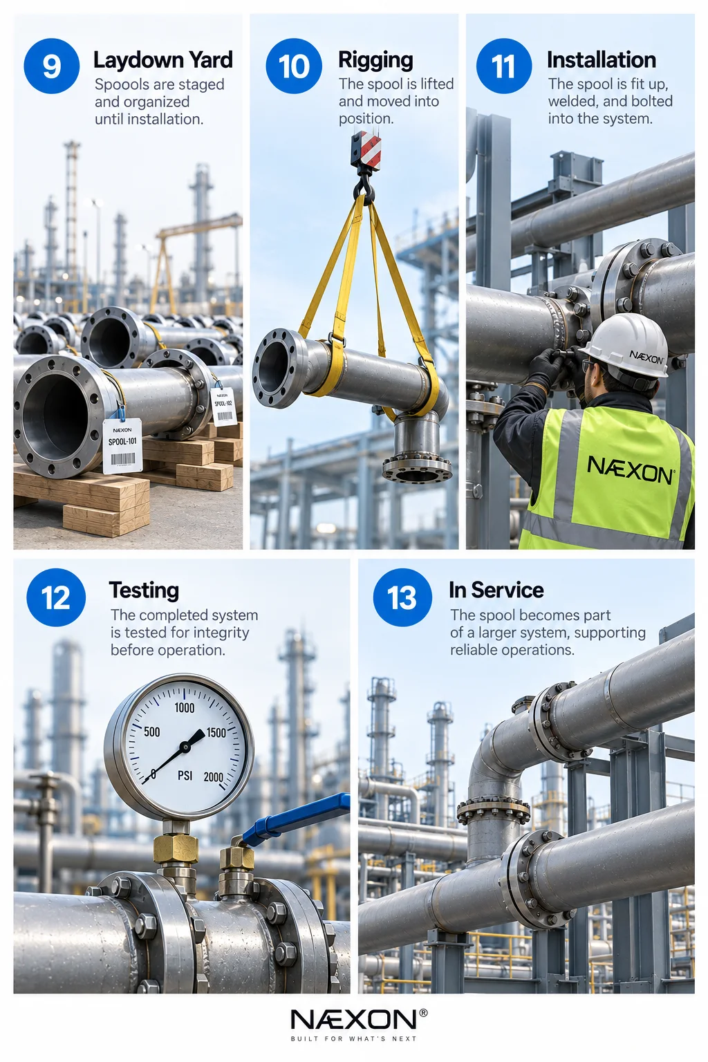
Figure 3. The final stages of an industrial pipe spool: staging in the laydown yard, rigging into position, installation, system testing, and final placement into service.
When the spool arrives at the project, it may not immediately be installed.
It can spend time in a laydown yard waiting for the structure, equipment, supports, or connecting piping to become ready.
Material-control personnel and field crews have to locate and stage the correct spool when installation begins.
On a large project, this can become a major logistical operation.
The perfect spool isn’t very useful if nobody can find it.
The Pipefitter Finally Gets the Spool
This is where the drawing meets reality.
The field crew receives the spool, identifies its location, verifies orientation, and plans the installation.
Before rigging begins, experienced crews often verify important dimensions.
They may check equipment nozzles, existing piping, structural clearances, support locations, flange faces, centerline elevations, and tie-in points.
Why measure something that engineering already measured?
Because the field is the final truth.
Concrete moves.
Steel has tolerances.
Equipment can be positioned slightly differently.
Existing piping may not be exactly where historical drawings indicate.
Previous spools may have accumulated small dimensional differences.
Those differences can eventually reach the spool being installed.
Rigging Puts the Spool in Position
Industrial pipe spools can range from something one person can carry to assemblies requiring cranes and engineered lift plans.
The rigging method depends on the spool’s weight, shape, center of gravity, installation location, and available access.
The crew may use cranes, chain falls, come-alongs, slings, shackles, beam clamps, tuggers, or other approved rigging equipment.
The objective isn’t merely to lift the spool.
It has to arrive at the connection in the correct orientation while remaining controlled.
A spool containing valves, branches, or eccentric weight distribution can behave very differently from a straight piece of pipe.
Then Comes the Moment Everyone Notices
The spool reaches its final location.
Does it fit?
Ideally, the flange faces come together correctly, field-weld gaps are where they should be, centerlines align, supports match, and the spool settles into position without excessive force.
When that happens, dozens of earlier decisions have worked together successfully.
When it doesn’t, the crew begins troubleshooting.
Why Pipe Spools Sometimes Don’t Fit
A spool mismatch does not automatically mean the fabrication shop made a mistake.
The problem can originate almost anywhere in the dimensional chain.
Possible causes include incorrect field measurements, drawing revisions, fabrication errors, incorrect fitting takeoffs, flange rotation, accumulated tolerances, equipment movement, structural interference, wrong materials, incorrect orientation, or changes made elsewhere in the piping system.
Good field crews diagnose the cause before modifying anything.
Forcing a spool into position can transfer stress into piping, equipment nozzles, flanges, or supports.
The objective isn’t to make it fit.
The objective is to determine why it doesn’t fit.
Field Welds Complete the System
Many piping systems intentionally include field welds.
These provide practical locations where fabricated assemblies can be joined after installation.
The fitter aligns the connection, establishes the required gap, verifies orientation, and prepares the joint for welding.
Once the field weld is completed and accepted, two separate fabricated assemblies become one continuous piping system.
Piece by piece, the line takes shape.
Flanges Are Bolted Together
Flanged connections introduce another critical stage.
Gaskets must be correct for the service.
Flange faces must be clean and properly aligned.
Bolting must match the specification.
The connection should be assembled according to the project’s required bolting procedure.
Poor flange alignment should not simply be corrected by using the bolts to pull everything together.
Excessive force can introduce unwanted stress into the piping system or connected equipment.
Good fit-up happens before final tightening.
Supports Begin Carrying the Load
Once the piping is installed, its supports become part of the system.
Some supports carry dead weight.
Others guide movement.
Some restrain movement.
Spring supports may allow controlled vertical movement.
Anchors can establish fixed points.
The piping system isn’t necessarily intended to remain perfectly stationary.
Temperature changes can cause substantial thermal expansion and contraction.
That movement is part of the engineering design.
Installing the pipe correctly means respecting that design.
Testing Comes Before Operation
Before many industrial piping systems enter service, they undergo pressure or leak testing according to applicable requirements.
Hydrostatic testing commonly uses water, while other testing methods may be specified for particular systems.
The purpose is to verify system integrity before process material is introduced.
A completed test represents far more than one successful pressure reading.
It represents engineering, materials, fabrication, welding, inspection, installation, and quality control working together.
One Spool Represents an Entire Chain of Work
The finished pipe spool might ultimately disappear into a pipe rack where most people never think about it again.
But look closely and it tells a much larger story.
Someone designed the system.
Someone produced the drawing.
Someone ordered the material.
Someone verified the material.
Someone calculated the cuts.
Someone laid it out.
Someone fitted it.
Someone welded it.
Someone inspected it.
Someone transported it.
Someone located it in the yard.
Someone rigged it.
Someone installed it.
Someone tested it.
And eventually, someone will maintain it.
Industrial piping is rarely the work of one trade or one department. It is a chain of decisions where the accuracy of one step affects everything that follows.
Digital Tools Are Changing That Chain
One of the biggest opportunities in industrial piping is reducing the separation between drawing, calculation, fabrication, and installation.
NÆXON is developing its industrial tools around that idea.
Numerus handles pipe-trade calculations and dimensional work.
Rapit Pro helps generate pipe saddle patterns for branch fabrication.
Ayso provides a visual environment for building piping isometrics.
And In-dex is being developed as a comprehensive dimensional reference for piping components.
The long-term goal is straightforward: give the person doing the work faster access to the information needed to make the right decision.
Because whether the information starts on an engineering workstation or a pipefitter’s phone, eventually it has to become steel.
Field Rule
A pipe spool should never be viewed as an isolated piece of pipe.
Every dimension connects to something else.
Every flange has a mating connection.
Every branch has an orientation.
Every elevation relates to another point.
Every weld becomes part of a larger system.
The best pipefitters learn to see beyond the spool sitting in front of them.
They understand where it came from, where it’s going, and what has to happen next.
That is the difference between simply installing pipe and understanding the piping system.
This one would also work especially well with a step-by-step visual diagram showing Drawing → Material → Fabrication → Welding → Inspection → Shipping → Rigging → Installation → Testing.