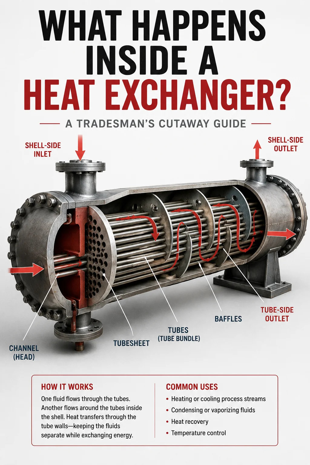
A Tradesman’s Cutaway Guide
Heat exchangers are everywhere in industrial facilities. Walk through a refinery, chemical plant, power plant, LNG facility, or large process unit and you’ll see them connected to piping systems throughout the plant. Some are small enough to stand beside. Others contain thousands of tubes and require cranes, specialized equipment, and entire crews to open during a turnaround.
From the outside, a shell-and-tube heat exchanger can look surprisingly simple: a large cylindrical shell with piping connected to several nozzles.
Inside, however, two separate fluids may be moving through completely different paths, separated by relatively thin metal tubes while transferring enormous amounts of heat.
Understanding what happens inside an exchanger helps pipefitters, welders, boilermakers, operators, millwrights, inspectors, and turnaround crews understand why the piping is arranged the way it is, what crews are actually repairing when an exchanger is opened, and why seemingly small internal problems can affect an entire process unit.
What Is a Heat Exchanger?
A heat exchanger is equipment designed to transfer thermal energy from one fluid to another without normally allowing those fluids to mix.
One fluid is hotter.
The other is colder.
Heat travels through a metal barrier separating them.
A simple conceptual example looks like this:HOT FLUID ───────────────► │ │ │ │ │ TUBES │ │ │ │ │ COLD FLUID ◄───────────────
The two process streams remain physically separated while heat passes through the tube wall.
Depending on the service, the exchanger may be used to heat, cool, condense, vaporize, recover heat, or control process temperature.
Why Industrial Plants Use Heat Exchangers
Industrial processes constantly create heat.
Throwing that energy away would be extremely inefficient.
Instead, plants often recover heat from one process stream and transfer it into another stream that needs heating.
Imagine a hot process stream leaving one part of a refinery at a high temperature. Somewhere else, another stream needs to be heated before entering the next piece of equipment.
Rather than burning additional fuel to create all of that heat, engineers may route the two streams through a heat exchanger.
The hot stream gives up some of its energy.
The colder stream absorbs it.
The plant effectively recycles heat that already exists in the process.
Across a large refinery, this heat recovery can represent an enormous amount of energy.
The Shell-and-Tube Heat Exchanger
Many exchanger designs exist, but one of the most important designs for industrial tradespeople to understand is the shell-and-tube heat exchanger.
Imagine placing hundreds or even thousands of small tubes inside one large pipe-like shell.
Conceptually: ┌───────────────────────────────┐ │ ========================== │ │ ========================== │ │ ========================== │ │ ========================== │ │ ========================== │ └───────────────────────────────┘ EXCHANGER SHELL
One fluid travels through the tubes.
Another fluid travels around the outside of those tubes inside the shell.
Those two paths are called:
Tube Side
and
Shell Side
Understanding the difference is fundamental to understanding an exchanger.
Tube Side Explained
The tube-side fluid travels through the exchanger tubes.
A simplified exchanger might look like:INLET → ======================== → OUTLET ======================== ======================== ========================
The process fluid enters the channel or head, is distributed into the tubes, travels through them, and eventually exits the exchanger.
The tubes provide a tremendous amount of surface area.
Instead of transferring heat through one large wall, hundreds or thousands of tubes expose a much greater metal surface to both fluids.
More usable heat-transfer surface generally allows more thermal energy to move between the two streams.
Shell Side Explained
The shell-side fluid flows through the space surrounding the tubes.
Imagine the tubes running horizontally while another fluid moves around them: SHELL-SIDE FLOW ↓ ┌─────────────────────────────┐ │ →→→ =================== │ │ =================== →→ │ │ →→→ =================== │ │ =================== →→ │ └─────────────────────────────┘
If the fluid simply traveled straight through the shell without being directed across the tube bundle, heat transfer might be less effective.
That’s where baffles become important.
What Are Baffles?
Baffles are internal plates installed throughout many shell-and-tube exchangers.
They force shell-side fluid to repeatedly change direction as it travels through the exchanger.
Instead of flowing directly from inlet to outlet:──────────────►
the fluid may follow a path more like:→ ↓ → ↑ → ↓ → ↑ →
This directs the shell-side fluid across the tubes and can increase turbulence and heat-transfer effectiveness.
Baffles can also provide mechanical support to the tubes and help limit excessive tube vibration.
Their exact geometry and spacing are engineering decisions based on exchanger design and service conditions.
The Tubesheet
At each end of many shell-and-tube exchangers is a thick plate called a tubesheet.
Hundreds or thousands of precisely located holes may be machined into it.
Each exchanger tube passes through one of those holes.
Conceptually: TUBESHEET ● ● ● ● ● ● ● ● ● ● ● ● ● ● ● ● ● ● ● ● ● ● ● ● ● ● ● ● ● ● ● ● ● ● ● ● ● ● ● ● ● ● ●
The tubes are mechanically expanded, welded, or otherwise attached and sealed to the tubesheet depending on exchanger construction.
The tubesheet performs an extremely important job: it helps maintain separation between the tube-side and shell-side fluids while supporting the tube bundle.
If a tube-to-tubesheet joint leaks, the two process streams may potentially communicate.
That can become a serious operating problem.
The Channel Head
At the end of the exchanger, the tube-side piping doesn’t normally connect individually to hundreds of tubes.
Instead, it connects to a channel or head.
The head distributes incoming fluid across the appropriate tubes.
In a simple one-pass exchanger:PIPE → [HEAD] → ==================== → [HEAD] → PIPE
The fluid enters one end, travels through the tubes once, and exits the other end.
But many exchangers use multiple tube passes.
What Does “Two-Pass” Mean?
A two-pass exchanger makes the tube-side fluid travel through the bundle twice.
Instead of entering one end and immediately leaving the opposite end, the channel arrangement redirects the fluid.
Conceptually:INLET → ======================== → │ │ OUTLET ← ======================== ←
The fluid travels through one group of tubes, turns around inside the opposite head, and travels back through another group.
Exchangers may have:
- One pass
- Two passes
- Four passes
- More complex arrangements
The number of passes affects velocity, pressure drop, heat transfer, nozzle arrangement, and exchanger performance.
Counterflow vs. Parallel Flow
Another important concept is the direction the two fluids travel relative to each other.
Parallel Flow
Both streams generally move in the same direction:HOT ─────────► COLD ─────────►
Counterflow
The streams move in opposite directions:HOT ─────────► COLD ◄─────────
Counterflow arrangements can provide favorable temperature-driving-force characteristics and are common in heat-exchanger design.
Actual shell-and-tube flow patterns can be considerably more complicated because of multiple passes and shell-side baffling.
What Actually Transfers the Heat?
The fluids don’t need to touch.
Heat travels from the hotter fluid through the tube wall into the colder fluid.
The basic path is:
Hot Fluid → Tube Wall → Cold Fluid
If the tube wall becomes covered with deposits, that heat-transfer path becomes less effective.
That leads us to one of the biggest exchanger problems encountered in industrial facilities.
Fouling
Over time, material can accumulate on heat-transfer surfaces.
Depending on the process, deposits might include:
- Scale
- Coke
- Corrosion products
- Minerals
- Sludge
- Biological material
- Process contaminants
This buildup is called fouling.
Imagine a clean tube:| | | FLUID | | |
Now imagine deposits building along the inside wall:|### ###| |## FLUID##| |### ###|
Those deposits create additional resistance to heat transfer and can restrict flow.
The exchanger may gradually lose performance even though it appears perfectly normal from the outside.
Why Exchangers Get Opened During Turnarounds
Heat exchangers are major turnaround equipment because they often need internal inspection, cleaning, repair, or testing.
During an outage, crews may:
- Isolate the exchanger
- Drain and prepare it according to facility procedures
- Remove connected piping as required
- Remove channel covers or heads
- Clean tubes
- Inspect tubesheets
- Inspect tube ends
- Perform NDE
- Plug damaged tubes when approved
- Repair tube-to-tubesheet joints
- Remove the tube bundle
- Replace gaskets
- Reassemble the exchanger
- Perform required leak or pressure testing
- Reinstall piping
- Return the equipment to service through the approved reinstatement process
This can involve pipefitters, boilermakers, welders, operators, inspectors, riggers, crane operators, scaffold builders, insulators, and other crafts working around the same equipment.
What Is a Bundle Pull?
On exchangers designed with removable bundles, the entire internal tube bundle can sometimes be pulled out of the shell.
Picture the exchanger shell remaining in place while the internal assembly slides outward:SHELL ┌─────────────────────────────┐ │ │ └─────────────────────────────┘ ← ========================= TUBE BUNDLE
Real bundles can be extremely heavy and long.
Removing one may require specialized bundle-pulling equipment, cranes, rigging plans, temporary supports, and careful coordination.
This is one reason exchanger work can become a major activity during a refinery turnaround.
Why Tubes Fail
Exchanger tubes operate in demanding environments.
Potential degradation mechanisms include:
- Corrosion
- Erosion
- Vibration
- Thermal cycling
- Fouling
- Mechanical damage
- Process chemistry
- Tube-to-baffle interaction
- Localized thinning
A tube doesn’t necessarily have to completely rupture before becoming unacceptable. Inspection may detect thinning or damage that requires repair or removal from service.
What Does It Mean to Plug a Tube?
Sometimes a damaged tube can be removed from active service by sealing it at the tubesheets using an approved engineered repair method.
Conceptually:NORMAL TUBE ● ============================ ● PLUGGED TUBE ■ ============================ ■
The process fluid can no longer travel through that tube.
Plugging a limited number of tubes may allow an exchanger to continue operating, depending on engineering evaluation and applicable requirements.
However, plugging too many tubes reduces available heat-transfer area and can affect exchanger performance and flow characteristics.
Tube plugging is therefore not simply a field decision—it must follow the facility’s approved engineering and repair requirements.
Why Exchanger Piping Can Be Difficult
From a pipefitter’s perspective, exchanger piping can become complicated because large nozzles may connect directly to equipment that must remain properly aligned.
Piping connected to exchanger nozzles must not simply be forced into position.
Excessive piping strain can place unwanted loads on equipment nozzles and potentially contribute to alignment or mechanical problems.
This is why proper fabrication dimensions, supports, fit-up, flange alignment, and installation sequence matter.
Why Nozzle Orientation Matters
Heat exchangers may have several nozzles serving completely different functions.
Depending on design, you might encounter:
- Tube-side inlet
- Tube-side outlet
- Shell-side inlet
- Shell-side outlet
- Vent
- Drain
- Relief connection
- Instrument connections
Connecting the wrong line to the wrong nozzle would fundamentally change how the equipment operates.
That is why tradespeople should verify nozzle identification using the appropriate P&ID, equipment drawing, piping isometric, and project documentation.
Why Exchangers Have Vents and Drains
Air or vapor can become trapped at high points.
Liquid can remain trapped at low points.
Therefore exchanger systems frequently include appropriately located vents and drains.
These connections may be important during:
- Filling
- Draining
- Hydrostatic testing
- Maintenance
- Startup
- Shutdown
Their exact purpose and operating procedure depend on the system.
A Simple Exchanger System
Now combine the concepts. SHELL-SIDE OUT ↑ │ ┌──────────────────────┐ TUBE IN ───► │ ==================== │ ───► TUBE OUT │ ==================== │ │ ==================== │ └──────────────────────┘ ↑ │ SHELL-SIDE IN
Two separate fluids enter the exchanger.
One travels through the tubes.
The other travels around them inside the shell.
Heat moves through the tube walls.
The fluids normally never mix.
That is the fundamental operating principle behind a shell-and-tube heat exchanger.
What Tradespeople Should Understand Before Working on One
You don’t need to design heat exchangers to work around them effectively.
But understanding the equipment makes the job easier.
Before beginning exchanger-related work, determine:
Which side are you working on?
Tube side or shell side?
What nozzle is involved?
Inlet, outlet, vent, drain, or another connection?
Is the bundle removable?
This affects maintenance planning and surrounding access.
What drawings apply?
P&ID, equipment drawing, piping isometric, plot plan, lifting plan, and project procedures may all contain relevant information.
What is the approved isolation and maintenance plan?
Never assume an exchanger is safe to open simply because the process appears shut down.
The Bigger Picture
A heat exchanger isn’t simply a large cylinder full of tubes.
It is an energy-transfer machine.
The shell, tubes, tubesheets, heads, baffles, nozzles, gaskets, supports, and connected piping all work together to keep two process streams separated while transferring heat efficiently.
Once you understand what is happening inside, many things you see in the field begin making more sense.
You understand why the exchanger has several large nozzles.
You understand why heads must be removed.
You understand why bundles get pulled.
You understand why tubes are cleaned.
You understand why inspectors examine tubes and tubesheets.
You understand why piping alignment matters.
And most importantly, you understand how one piece of equipment fits into the larger process.
Final Takeaway
The easiest way to remember a shell-and-tube heat exchanger is:
One fluid travels through the tubes.
Another fluid travels around the tubes inside the shell.
The tube wall keeps them separated while allowing heat to move between them.
Everything else—the baffles, tubesheets, passes, channel heads, bundle design, cleaning, inspection, and maintenance—is built around making that heat transfer reliable and efficient.
The next time you stand beside an exchanger during a turnaround, don’t just see a large piece of equipment.
Picture what is happening inside it.


