When working with flanges, knowing the nominal pipe size alone is not enough. A fitter may also need the flange class, outside diameter, bolt-circle diameter, number of bolts, bolt-hole diameter, and recommended stud size before beginning fit-up or bolt-up.
The chart below is designed as a practical field reference for ASME B16.5 Class 150 and Class 300 flanges. Dimensions should always be checked against the applicable project specification and current governing standard before fabrication or procurement.
Important: Flange Class 150, 300, 600, etc. is not a direct PSI rating. Allowable pressure depends on material and temperature.
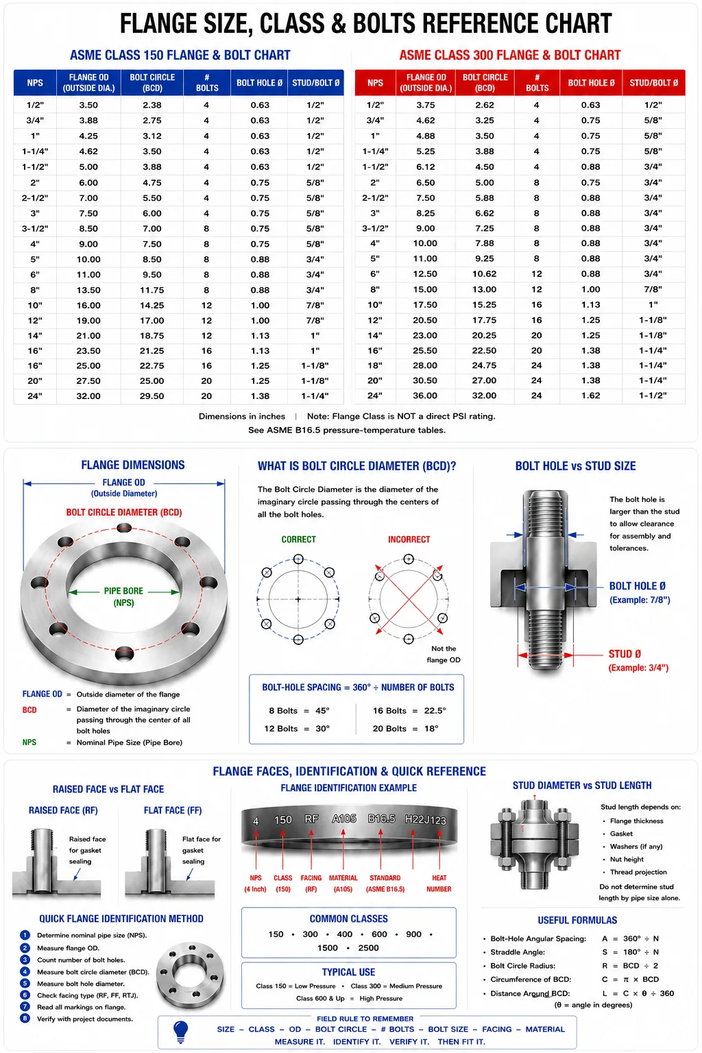
ASME Class 150 Flange & Bolt Chart
NPS
Flange OD
Bolt Circle
# Bolts
Bolt Hole Ø
Stud/Bolt Ø
1/2”
3.50”
2.38”
4
0.63”
1/2”
3/4”
3.88”
2.75”
4
0.63”
1/2”
1”
4.25”
3.12”
4
0.63”
1/2”
1-1/4”
4.62”
3.50”
4
0.63”
1/2”
1-1/2”
5.00”
3.88”
4
0.63”
1/2”
2”
6.00”
4.75”
4
0.75”
5/8”
2-1/2”
7.00”
5.50”
4
0.75”
5/8”
3”
7.50”
6.00”
4
0.75”
5/8”
3-1/2”
8.50”
7.00”
8
0.75”
5/8”
4”
9.00”
7.50”
8
0.75”
5/8”
5”
10.00”
8.50”
8
0.88”
3/4”
6”
11.00”
9.50”
8
0.88”
3/4”
8”
13.50”
11.75”
8
0.88”
3/4”
10”
16.00”
14.25”
12
1.00”
7/8”
12”
19.00”
17.00”
12
1.00”
7/8”
14”
21.00”
18.75”
12
1.13”
1”
16”
23.50”
21.25”
16
1.13”
1”
18”
25.00”
22.75”
16
1.25”
1-1/8”
20”
27.50”
25.00”
20
1.25”
1-1/8”
24”
32.00”
29.50”
20
1.38”
1-1/4”
ASME Class 300 Flange & Bolt Chart
Class 300 flanges generally become heavier and use larger and/or more numerous fasteners than their Class 150 counterparts.
NPS
Flange OD
Bolt Circle
# Bolts
Bolt Hole Ø
Stud/Bolt Ø
1/2”
3.75”
2.62”
4
0.63”
1/2”
3/4”
4.62”
3.25”
4
0.75”
5/8”
1”
4.88”
3.50”
4
0.75”
5/8”
1-1/4”
5.25”
3.88”
4
0.75”
5/8”
1-1/2”
6.12”
4.50”
4
0.88”
3/4”
2”
6.50”
5.00”
8
0.75”
5/8”
2-1/2”
7.50”
5.88”
8
0.88”
3/4”
3”
8.25”
6.62”
8
0.88”
3/4”
3-1/2”
9.00”
7.25”
8
0.88”
3/4”
4”
10.00”
7.88”
8
0.88”
3/4”
5”
11.00”
9.25”
8
0.88”
3/4”
6”
12.50”
10.62”
12
0.88”
3/4”
8”
15.00”
13.00”
12
1.00”
7/8”
10”
17.50”
15.25”
16
1.13”
1”
12”
20.50”
17.75”
16
1.25”
1-1/8”
14”
23.00”
20.25”
20
1.25”
1-1/8”
16”
25.50”
22.50”
20
1.38”
1-1/4”
18”
28.00”
24.75”
24
1.38”
1-1/4”
20”
30.50”
27.00”
24
1.38”
1-1/4”
24”
36.00”
32.00”
24
1.62”
1-1/2”
Understanding Flange Class
One of the most common misunderstandings about flanges is assuming that a Class 150 flange means 150 PSI.
It does not.
ASME pressure classes include commonly encountered designations such as:
150, 300, 400, 600, 900, 1500 and 2500.
These are pressure-temperature classes, not simple pressure limits.
The actual allowable working pressure depends on several factors, especially the flange material and operating temperature.
For example, two Class 150 flanges manufactured from different material groups may not necessarily have identical allowable pressure at a particular elevated temperature.
Therefore, do not write:
Class 150 = 150 PSI
Instead, think:
Class identifies the flange pressure-temperature rating system.
The applicable ASME pressure-temperature table and project specification determine the actual allowable pressure.
What Is Bolt Circle Diameter?
The Bolt Circle Diameter, commonly abbreviated BCD, is the diameter of the imaginary circle passing through the centers of all the bolt holes.
It is one of the most useful flange dimensions for fitters and fabricators.
If you draw a circle through the center of every bolt hole, that circle is the bolt circle.
Do not confuse it with the flange outside diameter.
For example, a flange might have:
Flange OD = 13.500”
while having:
Bolt Circle = 11.750”
Those are completely different dimensions.
Number of Bolts vs. Number of Bolt Holes
When a chart says:
8 bolts
the flange contains:
8 bolt holes.
When two flanges are assembled, eight studs or bolts pass through those corresponding holes.
The number of bolt holes also determines the angular spacing.
Use:
Bolt-hole spacing = 360° ÷ number of holes
For an eight-hole flange:
360° ÷ 8 = 45°
Each hole is therefore separated by:
45°
For twelve holes:
360° ÷ 12 = 30°
For sixteen holes:
360° ÷ 16 = 22.5°
For twenty holes:
360° ÷ 20 = 18°
This is the same geometry used when calculating flange clocking.
Bolt Holes Normally Straddle the Centerline
For conventional flange orientation, bolt holes generally straddle the natural centerline.
That means you normally don’t put a bolt hole directly at 12 o’clock.
Instead, two holes sit equally on either side.
The formula for the straddle angle is:
Straddle angle = 180° ÷ number of bolt holes
For eight holes:
180 ÷ 8 = 22.5°
The closest holes therefore sit:
22.5° on either side of the centerline.
For twelve holes:
180 ÷ 12 = 15°
For sixteen holes:
180 ÷ 16 = 11.25°
This is the mathematical basis of two-holing a flange.
Why Is the Bolt Hole Larger Than the Stud?
Look at the chart and you’ll notice something important.
A:
3/4” stud
does not go through a:
3/4” hole.
The bolt hole is larger.
For example, many flange configurations using a 3/4-inch stud have an approximately:
7/8-inch bolt hole.
That clearance makes assembly possible and allows normal manufacturing and installation tolerances.
The exact dimensions should always come from the applicable flange standard rather than being assumed from the stud diameter.
Flange OD Gets Larger as Class Increases
Compare a 6-inch flange.
A Class 150 flange is approximately:
11” OD
while a Class 300 flange is approximately:
12.5” OD
The Class 300 flange also uses a different bolt arrangement.
That illustrates an important field rule:
Pipe size alone does not identify a flange.
A fitter should know both:
NPS + Class
For example:
6” Class 150
is not interchangeable with:
6” Class 300.
Stud Diameter Is Not Stud Length
The chart above lists the diameter of the stud or bolt.
It does not tell you the required stud length.
Stud length depends on the complete bolted joint, including flange type and thickness, gasket, washers when specified, nuts, equipment connections, insulating kits, and required thread projection.
A weld-neck flange-to-flange connection may require a different stud length than a flange-to-valve connection even when both connections use the same nominal pipe size and class.
Never determine stud length solely from pipe size.
Raised-Face vs. Flat-Face Flanges
Flange facing also matters.
Common flange faces include:
Raised Face (RF)
Flat Face (FF)
Ring-Type Joint (RTJ)
The facing affects gasket selection and, in some cases, the overall bolted-joint dimensions.
Do not assume that two flanges with the same NPS, class, and bolt pattern automatically belong together.
The facing and material requirements must also match the engineered connection.
Why This Information Matters During Fabrication
Imagine receiving a flange without a readable marking.
Knowing the OD, bolt-circle diameter, number of holes, and bolt-hole diameter can help identify what you are looking at.
For example, you could measure:
Flange OD
then:
Bolt Circle
then count:
Bolt Holes
then measure:
Bolt-Hole Diameter
Those measurements can be compared with the applicable flange standard.
This can help narrow down the size and class.
But identification by dimensions should never replace required material traceability, markings, MTRs, or project QA/QC requirements.
Quick Flange Identification Method
When trying to identify an unknown flange in the field, start with the pipe or flange bore to determine the likely nominal size. Measure the flange outside diameter. Count the bolt holes. Measure the bolt circle. Measure the bolt-hole diameter. Check the facing, then read every available marking around the flange rim.
Typical markings may identify the manufacturer, nominal size, pressure class, material specification, heat number, and applicable standard.
Compare those markings and measurements with the approved project documentation.
A Fitter’s Quick Math
There are several formulas worth remembering.
Bolt-Hole Angular Spacing
A = 360° ÷ N
where:
A = angle between holes
N = number of bolt holes
Standard Straddle Angle
S = 180° ÷ N
Bolt-Circle Radius
If you know bolt-circle diameter:
R = BCD ÷ 2
Circumference of the Bolt Circle
C = π × BCD
Distance Around Bolt Circle for a Given Angle
L = C × θ ÷ 360
These formulas become especially useful when laying out fabricated flanges, checking bolt-hole locations, or understanding unusual flange clocking.
Example: 12-Inch Class 150 Flange
From the chart:
Nominal Pipe Size: 12”
Class: 150
Flange OD: 19”
Bolt Circle: 17”
Number of Bolts: 12
Bolt Hole: 1”
Stud Diameter: 7/8”
Now calculate angular spacing:
360° ÷ 12 = 30°
Each bolt hole is:
30° apart.
Calculate the standard straddle:
180° ÷ 12 = 15°
Therefore the closest bolt-hole centers normally sit:
15° to either side of the reference centerline.
This is a perfect example of how a dimension chart and pipefitter math work together.
Don’t Identify a Flange by One Measurement
A single measurement can fool you.
Two different flanges may have similar outside diameters while having different bolt circles, hole counts, thicknesses, facing, materials, or pressure classes.
A much better identification uses several pieces of information together:
NPS + Class + OD + BCD + Hole Count + Hole Diameter + Facing + Markings
That gives you a much more reliable picture of what the flange actually is.
Field Rule to Remember
When somebody tells you:
“Bring me a six-inch flange.”
there still isn’t enough information.
You may need to know whether it is Class 150, 300, 600, or another class; weld neck, slip-on, blind, socket weld, threaded, or lap joint; raised face, flat face, or RTJ; carbon steel, stainless steel, alloy, or another material; and the required bore or schedule where applicable.
That’s why experienced fitters learn to look beyond nominal pipe size.
A flange is a complete engineered component.
The number stamped on its side tells only part of the story.
Næxon Field Reference
For everyday flange work, remember these six pieces of information:
SIZE — CLASS — OD — BOLT CIRCLE — NUMBER OF BOLTS — BOLT SIZE
Once you understand those, you can quickly interpret most of the physical information in a basic flange chart.
Then combine it with flange type, facing, material, pipe schedule, gasket requirements, and the project specification before making the actual connection.
Measure it. Identify it. Verify it. Then fit it.


