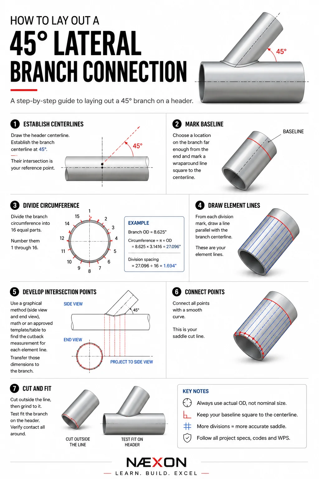
A 90° branch is relatively straightforward. Turn that branch to 45°, however, and the layout changes dramatically.
The intersection between the branch and header becomes an asymmetrical saddle. One side of the branch extends farther than the other, and trying to create the cut with a simple eyeballed fishmouth can leave large gaps.
This guide explains the field-layout principles behind a 45° lateral branch, including how to divide the pipe, establish reference lines, transfer measurements and develop the cut.
Important: This is a fabrication/layout guide, not a substitute for an engineered piping specification. Branch type, reinforcement, weld details, material, pressure class and whether a fabricated lateral is permitted must come from the applicable drawings, code and project specifications.
What Is a 45° Lateral?
A lateral is a branch connection entering or leaving the main pipe at an angle other than 90°.
For this example:
Header centerline = 0° reference
Branch centerline = 45° from the header centerline
Viewed from the side, the two centerlines intersect at 45°.
The difficulty is that we’re joining two cylinders, not two flat surfaces. The intersection of those cylindrical surfaces creates the curved saddle profile that must be developed onto the branch.
Traditional pipe-layout methods solve this by drawing the side/end views, dividing the circumference into equal sections, projecting those divisions through the intersection, and transferring the resulting points onto a flat development. (Open Oregon)
1. Start With the Actual Pipe OD
Do not perform this layout using nominal pipe size as though it were the outside diameter.
You need the actual outside diameter (OD) of both pipes.
Call them:
H = Header OD
B = Branch OD
And:
Rh = H ÷ 2
Rb = B ÷ 2
For example, if you’re working with NPS 8 Schedule 40 pipe, the nominal designation is 8 inches, but the actual OD is 8.625 inches.
That actual OD controls the geometry.
This distinction is fundamental throughout pipe layout and fabrication.
2. Establish the 45° Centerline
Before worrying about the saddle, establish the relationship between the pipes.
Draw or mark the header centerline.
Then establish the branch centerline at:
45°
The intersection of those two centerlines becomes the primary reference point for the layout.
A traditional full-size layout can be constructed by drawing parallel lines on either side of the centerlines at distances equal to the respective pipe radii. Those lines represent the outside surfaces of the pipes.
This geometric approach is a standard method for developing full-size 45° lateral layouts. (Scribd)
3. Mark a Reference Line Around the Branch
Choose a location far enough from the end of the branch that the entire saddle profile will fall between your reference line and the end of the pipe.
Use a wraparound to establish a line completely around the pipe.
This becomes your:
BASELINE
Every saddle measurement will be referenced from this line.
Accuracy here matters.
If the baseline isn’t square to the branch centerline, every measurement transferred from it will contain error.
4. Divide the Branch Circumference
Now divide the circumference into equal sections.
A useful detailed layout uses:
16 divisions
The spacing between divisions is:
Branch circumference ÷ 16
Since:
Circumference = π × OD
then:
Division spacing = π × Branch OD ÷ 16
Example
Suppose the branch OD is:
8.625”
Circumference:
8.625 × π = approximately 27.096”
Divide by 16:
27.096 ÷ 16 = approximately 1.694”
So each circumferential division is about:
1.694”
Using a wraparound or circumference tape, mark those divisions around the pipe.
Number them:
1 through 16
A 16-division layout gives you a series of control points from which the saddle curve can be developed. Published 45° lateral layout procedures likewise use circumferential divisions and transfer corresponding points to create the finished template. (Fabricator Guide)
5. Draw Longitudinal Element Lines
From each circumferential division, draw a straight line parallel with the branch centerline.
These are called element lines.
Imagine slicing the cylindrical pipe lengthwise into narrow strips.
Each line represents one location on the circumference where we need to determine the exact intersection with the header.
Instead of guessing at one complicated curve, we’re finding a series of individual points.
Once those points are connected, the saddle appears.
6. Understand Why a 45° Saddle Is Uneven
This is one of the most important concepts.
A 90° branch produces a saddle that is symmetrical from front to back.
A 45° lateral does not.
Because the branch approaches the header diagonally, one side reaches farther along the header than the other.
This creates an asymmetrical profile.
One end of the branch becomes the long side of the lateral.
The opposite becomes the short side.
The geometry of angled cylindrical intersections confirms this behavior: at angles such as 45°, the saddle profile becomes asymmetric rather than the balanced profile associated with a perpendicular branch. (Welding Fabrication World)
7. Develop the Intersection
There are several ways to obtain the individual cut dimensions.
In the traditional graphical method, draw a full-size side view of the header and branch.
Then draw the end view.
Divide the circular end view into the same number of divisions used on the actual pipe.
Project each division through the side view until it intersects the header surface.
Each intersection produces a measurement.
Those measurements are transferred back to the corresponding element lines on the branch.
The sequence becomes:
Circular division → projection → intersection → measurement → branch element line
Repeat this around the circumference.
This projection/development method is one of the classic ways of laying out lateral connections and can be adapted to angles other than 45°. (Open Oregon)
8. Transfer the Measurements to the Pipe
Return to the actual branch.
You should now have:
- A baseline
- 16 circumferential divisions
- 16 longitudinal element lines
- A calculated or developed cutback for each line
Measure from the same baseline along every element line.
Do not alternate reference points.
For example, your layout might conceptually look like:
Line 1 → Measurement A
Line 2 → Measurement B
Line 3 → Measurement C
…and so on around the pipe.
Mark every point carefully.
This is where patience pays off.
One wrong number can create a noticeable flat spot or gap in the finished saddle.
9. Connect the Points
Once all points are established, connect them with a smooth curve.
Do not connect them with straight segments.
You’re recreating the intersection between two curved surfaces.
Use a flexible strip, wraparound or another suitable layout aid to fair the line smoothly through the marks.
Look at the complete profile before cutting.
The curve should transition naturally from one point to the next.
If one point suddenly sticks far outside the surrounding curve, stop.
Recheck that measurement.
A smooth curved line through the developed points forms the final template profile. (Open Oregon)
10. Mark Before You Cut
Before reaching for a torch or grinder, verify:
Branch angle: 45°
Header OD: Correct
Branch OD: Correct
Baseline: Square
Circumference divisions: Equal
Element lines: Parallel
Measurements: Taken from the same reference
Cut side: Clearly identified
Mark the scrap side.
This simple habit can save a piece of pipe.
11. Cut Outside the Layout Line
When hand cutting, don’t immediately destroy your finished dimension.
Leave a small amount of material outside the layout line.
Then grind back to the line.
The exact allowance depends on the cutting process, material, pipe size and fabrication requirements.
The goal is simple:
Cut rough. Finish accurately.
It is much easier to remove another 1/16” than put 1/16” back onto the pipe.
12. Test-Fit the Branch
Place the branch against the header at 45°.
Check the entire circumference.
You’re looking for consistent contact and the root opening required by the approved weld detail.
Don’t judge only the top.
Check:
Crown
Sides
Heel
Long point
A lateral that appears excellent from one side can still have a large opening hidden on the opposite side.
13. Transfer the Opening to the Header
Once the branch has been properly fitted and positioned, its intersection can be transferred to the header using the approved fabrication procedure.
The header opening must correspond with the branch geometry.
Traditional lateral-layout procedures can also develop the header opening independently by dividing the header circumference and transferring the required dimensions. (Scribd)
Don’t assume the header opening is simply a round hole.
At 45°, the projected intersection is elongated.
Why 16 Divisions?
Could you use fewer divisions?
Yes.
But every division represents another known point on the curve.
Imagine trying to draw a circle using four points.
Now imagine using sixteen.
More correctly developed points allow you to reproduce the cylindrical intersection more accurately.
For many field layouts, 16 divisions provide a useful balance between accuracy and practicality.
For especially large-diameter or precision fabrication, the required layout method should follow the project’s fabrication procedure.
Equal vs. Unequal 45° Laterals
There are two situations worth distinguishing.
Equal Lateral
Header OD = Branch OD
Example:
12” × 12” at 45°
The geometry is comparatively straightforward because both cylinders have the same diameter.
Unequal Lateral
Header OD ≠ Branch OD
Example:
18” header × 8” branch at 45°
Now the intersection depends on both radii.
The same development principle still works, but the resulting saddle dimensions change significantly. Published fabrication methods for unequal 45° lateral branches likewise calculate different cutbacks at each circumferential position. (Fabricator Guide)
The Geometry Behind the Layout
The field method can feel like a collection of marks and measurements, but there is a simple idea underneath it.
You are finding:
Where does each longitudinal element of the branch intersect the cylindrical surface of the header?
At 90°, those intersections form a symmetrical saddle.
At 45°, the branch is effectively stretched across the header in the longitudinal direction.
That’s why the familiar 45° relationship involving √2 ≈ 1.414 repeatedly appears in 45° pipefitting calculations.
But don’t make the mistake of simply multiplying one saddle dimension by 1.414 and assuming you’ve developed an accurate lateral.
A real branch-to-header intersection depends on:
Header radius + branch radius + branch angle + circumferential position.
The complete saddle is a three-dimensional cylindrical intersection.
A Faster Shop Method: Make a Reusable Template
If you’re fabricating several identical laterals, don’t lay out every pipe from scratch.
Develop one accurate pattern.
Transfer it onto suitable template material.
Cut and verify it.
Label it clearly:
HEADER SIZE
BRANCH SIZE
ANGLE
OD
ORIENTATION
Then reuse it.
This is one reason templates have been so valuable in fabrication shops long before CNC pipe-cutting machines existed.
Common 45° Lateral Layout Mistakes
Most bad lateral fits come from a surprisingly small group of mistakes:
- Using nominal pipe size instead of actual OD
- Starting from a baseline that isn’t square
- Mixing up circumferential division numbers
- Measuring from different reference points
- Reversing the long and short sides
- Connecting points with straight lines instead of a smooth curve
- Cutting directly on the finished line
- Forgetting the required weld/root-gap preparation
- Assuming the header opening is circular
- Eyeballing the branch angle instead of establishing a true 45°
The mathematics can be perfect and the fit can still be wrong if the marks aren’t transferred accurately.
Field Rule: Establish References Before Measurements
A good pipe layout usually starts with references, not numbers.
Establish:
Centerline → 45° angle → baseline → circumference divisions → element lines → cutbacks → smooth profile
That order matters.
When your reference geometry is correct, the measurements have somewhere reliable to live.
When the references are wrong, adding more measurements simply makes the wrong layout more precise.
45° Lateral Layout — Quick Sequence
1. Verify header and branch actual ODs.
2. Establish the header centerline.
3. Establish the branch centerline at 45°.
4. Mark a square baseline around the branch.
5. Calculate the branch circumference.
6. Divide the circumference into 16 equal sections.
7. Draw longitudinal element lines.
8. Develop the intersection points graphically, mathematically or from an approved template/table.
9. Transfer every cutback from the same baseline.
10. Connect the points with a smooth curve.
11. Mark the scrap side.
12. Rough-cut outside the line.
13. Grind to the finished profile.
14. Position the branch at 45° and verify the fit around the entire circumference.
15. Prepare and weld according to the approved drawing, WPS and project requirements.
Learn the Geometry, Not Just the Numbers
A template can tell you where to cut.
Understanding the layout tells you why you’re cutting there.
That’s the skill worth learning.
Once you understand centerlines, circumferential divisions, element lines and projection, a 45° lateral stops looking like a mysterious curved cut.
It becomes a series of known points.
And once those points are established accurately, the pipe itself draws the curve for you.


