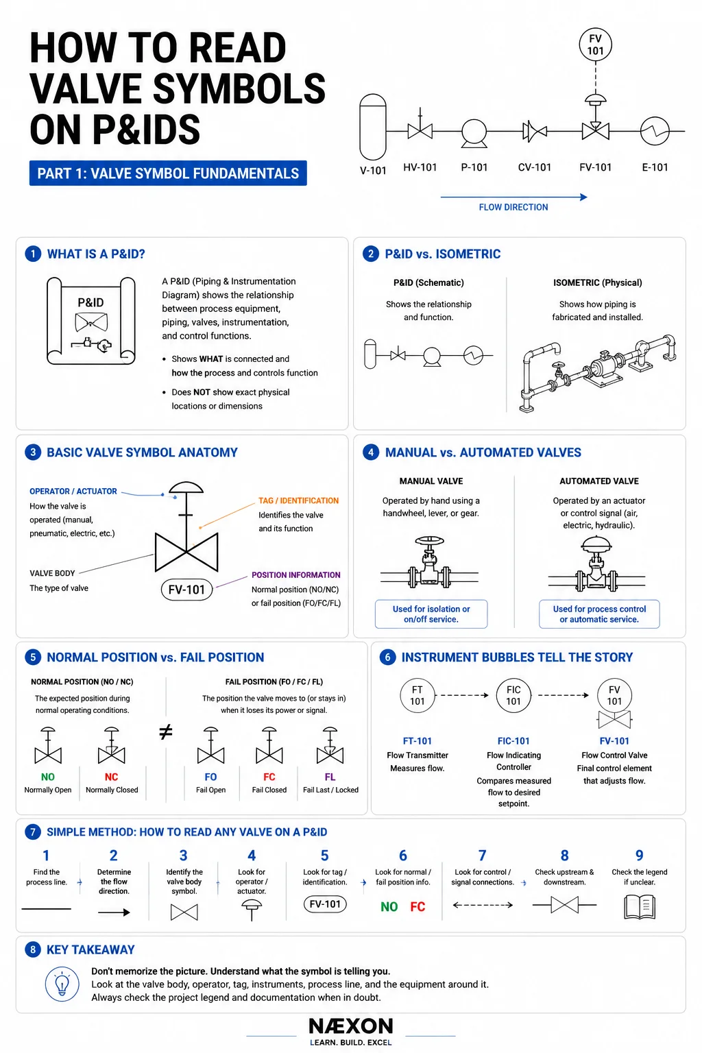
A P&ID can look like a wall of lines, circles, letters, valves, instruments, and equipment when you first open one.
But there is a much easier way to look at it.
Instead of trying to understand the entire drawing at once, learn to recognize the individual pieces. Find the equipment. Find the piping. Follow the process flow. Identify the valves. Then determine how those valves are operated and what instruments are controlling them.
Once you learn that pattern, a complicated P&ID starts becoming a map of what the process is supposed to do.
This first part of the Næxon How to Read Valve Symbols on P&IDs series starts with the foundation: how valve symbols work, what information surrounds them, and how to approach an unfamiliar symbol without guessing.
What Is a P&ID?
P&ID stands for Piping and Instrumentation Diagram.
It is one of the most important drawings used in refineries, chemical plants, power plants, processing facilities, manufacturing plants, terminals, and other industrial facilities.
A P&ID represents the relationship between major process equipment, piping, valves, instrumentation, and control functions.
Depending on the project and drawing standard, a P&ID may show things such as:
- Process equipment
- Process piping
- Pipe identification
- Valves
- Control valves
- Instruments
- Control loops
- Flow direction
- Drains and vents
- Equipment connections
- Relief devices
- Tie-ins
- Reducers and other piping components
For a pipefitter, operator, instrument technician, engineer, planner, inspector, or maintenance worker, learning to follow a P&ID means learning how the pieces of a process are connected.
A P&ID Is Not an Isometric Drawing
This distinction is extremely important.
A P&ID tells you primarily what is connected and how the process and controls function.
A piping isometric tells you primarily how the piping is physically fabricated and installed.
An isometric may provide dimensions, weld locations, fittings, elevations, coordinates, spool information and fabrication details.
A P&ID is much more schematic.
For example, a P&ID could show:
VESSEL → VALVE → PUMP → CHECK VALVE → CONTROL VALVE → HEAT EXCHANGER
That sequence tells you something about the process.
It does not mean those components physically sit in a perfectly straight line.
The actual pipe might turn vertically, travel through a pipe rack, change elevation several times and run hundreds of feet before reaching the next piece of equipment.
That physical routing is normally found on other project drawings.
Start With the Process Line
When learning P&IDs, resist the temptation to immediately decode every instrument bubble and abbreviation.
Start with the piping.
Find a major piece of equipment such as a:
Tank
Vessel
Pump
Compressor
Heat exchanger
Reactor
Boiler
Then locate the process line entering or leaving it.
Follow that line across the drawing.
As you follow it, ask:
Where does this line come from?
Where does it go?
Which valves are installed in it?
What equipment does it pass through?
Are there branches?
Are there drains or vents?
Are instruments connected to it?
That simple habit is one of the fastest ways to begin understanding P&IDs.
Understanding the Basic Valve Symbol
At its simplest, a valve symbol tells you:
There is a valve here.
But additional details can tell you considerably more.
Think of a complete valve representation as having several possible layers:
Valve body
- ●
Operator or actuator
- ●
Identification
- ●
Normal or failure position
- ●
Instrumentation/control information
Not every valve will show every one of these pieces.
The key is learning to read them separately.
1. The Valve Body
The center portion of the symbol represents the valve itself.
Different valve-body symbols can be used to distinguish different types of valves.
Depending on the drawing standard, you may encounter representations for:
Gate valves
Globe valves
Ball valves
Butterfly valves
Plug valves
Needle valves
Check valves
Control valves
Pressure-relief devices
and many others.
Don’t try to memorize all of them on your first day.
First learn to recognize:
Something is interrupting the process line, and that something is a valve.
Then determine what type.
Part 2 of this series will break down the common manual-valve symbols individually.
2. The Operator
After identifying the valve body, look at what is shown above or attached to it.
That information may indicate how the valve is operated.
A valve might be:
Manually operated
Pneumatically operated
Electrically operated
Hydraulically operated
Solenoid operated
or controlled through another type of actuator arrangement.
This distinction matters.
A manual isolation valve and an automatically controlled process valve can perform very different jobs even though both are valves installed in piping.
Later in this series, we’ll break down actuator symbols and control valves in detail.
3. The Valve Tag
A valve may also have an identification tag.
For example:
FV-101
Those letters and numbers aren’t random.
In a common instrumentation-tagging convention:
F relates to flow.
V identifies the final control element as a valve.
101 identifies the associated loop or system according to the project’s numbering convention.
You may encounter tags such as:
FV — Flow Valve
LV — Level Valve
PV — Pressure Valve
TV — Temperature Valve
But this is where an important P&ID rule begins:
Never Assume a Project Uses the Exact Convention You Learned Somewhere Else
Standards create consistency, but companies and projects can have their own conventions.
The project’s documentation and legend are the authority.
The Legend Is Your Best Friend
Experienced workers don’t need to pretend they recognize every symbol.
They know where to look.
A P&ID drawing set typically provides legends, notes, abbreviations, or project standards that define the symbols being used.
If you encounter an unfamiliar valve symbol, don’t guess based on what it vaguely resembles.
Check the legend.
This becomes especially important when moving between:
- Different owners
- Different engineering companies
- Older facilities
- New construction
- International projects
- Legacy drawings
- Modified drawings
A symbol you saw on one project may be represented differently somewhere else.
Manual Valve vs. Automated Valve
One of the first distinctions you should learn to make is whether you’re looking at a manual valve or an automated valve.
A manual valve requires someone to physically operate it through a handwheel, lever, gear operator, or similar mechanism.
An automated valve uses some form of actuator or control mechanism.
That actuator might respond to:
Instrument air
Electric power
Hydraulic pressure
A solenoid
A control system command
This becomes extremely important when reading process-control systems.
Isolation Valve vs. Control Valve
Another major mistake beginners make is assuming every valve has essentially the same purpose.
It doesn’t.
An isolation valve is generally intended to isolate equipment or a section of piping.
A control valve can continuously or periodically change position to regulate a process variable.
Imagine water flowing through a pipe.
An isolation valve might normally be fully open during operation and closed when the system needs to be isolated.
A control valve might constantly adjust between positions to maintain the required flow.
Same basic concept—a restriction in a pipe.
Completely different purpose.
Understanding Flow Direction
Before deciding what a valve does, determine which direction the process is moving.
Many P&IDs provide arrows showing process-flow direction.
Suppose you see:
TANK → PUMP → CHECK VALVE → HEAT EXCHANGER
The arrows tell you the intended direction of process flow.
This becomes especially important with directional devices such as check valves.
A check valve is intended to permit flow in one direction while preventing or limiting reverse flow.
Install one backward and you may have created a serious problem.
We’ll go much deeper into this in Part 3: Check Valves & Flow Direction.
Normally Open and Normally Closed
Some P&IDs indicate a valve’s normal position.
You may encounter designations such as:
NO — Normally Open
or
NC — Normally Closed
This information can be extremely important when trying to understand how a system is intended to operate.
Consider a simple bypass arrangement.
You might have two isolation valves normally open on the main process path while the bypass valve remains normally closed.
That tells you something immediately about how the system is intended to function during normal operation.
But there’s another concept that beginners frequently confuse with normal position.
Normal Position Is Not the Same as Fail Position
A valve’s normal operating position and its failure position are different concepts.
An automated valve may be designed to:
Fail Open
Fail Closed
or remain in another defined state following loss of its operating energy or control signal, depending on the design.
For example, engineers might design certain fuel-service valves to move closed under a specified failure condition.
Another application might require continued cooling, making an open failure position preferable.
Those are only examples.
Never determine an actual valve’s failure position from a general rule of thumb.
The project documentation determines the intended action.
We will cover this extensively in Part 7: Normally Open, Normally Closed & Fail Positions.
Instrument Bubbles Change the Story
Now we get into the part that makes P&IDs especially useful.
Suppose you see:
FT-101
connected through the control system to:
FIC-101
which ultimately controls:
FV-101
You aren’t simply looking at three unrelated tags.
You’re looking at a control loop.
A simplified interpretation could be:
FT-101 — Flow Transmitter
↓
Measures process flow
↓
FIC-101 — Flow Indicating Controller
↓
Evaluates the measured flow against the desired condition
↓
FV-101 — Flow Control Valve / final control element
↓
Changes valve position to influence process flow
Now the drawing is telling a story.
The instrument measures something.
The control system interprets it.
The valve responds.
That is one of the major breakthroughs when learning to read P&IDs.
Read the System, Not Just the Symbol
Imagine a simplified process:
TANK
↓
MANUAL ISOLATION VALVE
↓
PUMP
↓
CHECK VALVE
↓
FLOW TRANSMITTER
↓
CONTROL VALVE
↓
HEAT EXCHANGER
A beginner may see seven individual objects.
An experienced reader sees a process.
Fluid leaves storage.
A manual valve provides isolation.
The pump moves the fluid.
The check valve helps prevent reverse flow.
The transmitter measures flow.
The control valve regulates the process.
The fluid then enters the heat exchanger.
That’s the goal.
Don’t just identify symbols. Understand why they’re connected.
Valve Symbols Don’t Tell You Everything
This is another important lesson.
A P&ID contains enormous amounts of information, but it is not intended to answer every fabrication or installation question.
Depending on the project’s documentation, information such as exact physical dimensions, coordinates, spool geometry, weld locations and detailed routing may need to be obtained from other drawings and specifications.
That is why industrial workers often use several documents together:
P&ID
Piping isometric
Equipment drawings
Plot plans
Line lists
Valve lists
Instrument indexes
Specifications
Vendor drawings
Work packages
One drawing rarely tells the entire story.
If you’re new to shutdown and refinery documentation, Næxon’s Refinery Turnaround Dictionary: 100 Terms Every Shutdown Worker Should Know is another useful reference for terminology you’ll encounter around process equipment, isolation, tie-ins, work packages, redlines and turnarounds.
A Simple Method for Reading Any Valve on a P&ID
When you encounter a valve symbol, mentally work through the same sequence every time:
- Find the process line.
- Determine the intended flow direction.
- Identify the valve-body symbol.
- Look for an operator or actuator.
- Look for a valve or instrument tag.
- Look for normal-position information.
- Look for control or signal connections.
- Determine what equipment is upstream and downstream.
- Check the drawing legend when anything is unclear.
Eventually you won’t consciously think through every step.
You’ll simply start reading the drawing.
Example: Follow the Process
Consider this simplified system:
V-101 → HV-101 → P-101 → CHECK VALVE → FT-102 → FV-102 → E-101
Even without seeing the full drawing, you can begin breaking the system into pieces.
V-101
A vessel or other project-defined equipment designation.
↓
HV-101
A manually operated valve under a common tagging convention, subject to the project’s legend.
↓
P-101
A pump.
↓
CHECK VALVE
Provides directional flow protection.
↓
FT-102
Flow transmitter.
↓
FV-102
Flow-related final control valve.
↓
E-101
Often an exchanger or other equipment designation depending on the project’s equipment-tagging standard.
Now ask yourself:
Where is the manual isolation?
HV-101.
What prevents reverse flow toward the pump?
The check valve.
What measures flow?
FT-102.
What changes position to control the process flow?
FV-102.
You’re no longer memorizing shapes.
You’re reading the system.
Why This Matters in the Field
P&IDs aren’t just engineering-office drawings.
During construction, commissioning, maintenance and refinery turnarounds, workers may use P&IDs to help understand:
What equipment is connected
Where isolation points are located
Which valves belong to a system
How instrumentation interacts with piping
Where modifications are being made
What equipment is upstream or downstream
How a process is intended to function
That makes P&ID literacy useful across numerous trades.
Pipefitters need it.
Instrument technicians need it.
Operators live by it.
Planners use it.
Inspectors use it.
Supervision uses it.
Engineers use it.
The better you understand the drawing, the easier it becomes to understand the job.
For workers moving into shutdown and maintenance environments, Næxon also has a broader guide to industrial workwear, PPE and safety gear for the conditions commonly encountered across refineries, power plants and industrial facilities.
The Most Important Rule
If you remember only one thing from Part 1, remember this:
Don’t Memorize the Picture. Understand What the Symbol Is Telling You.
Look at the valve body.
Look at the operator.
Look at the tag.
Look at the process line.
Look at the instrumentation.
Look at what comes before it.
Look at what comes after it.
Then check the project legend.
When those pieces begin making sense together, a P&ID stops looking like a collection of mysterious symbols and starts looking like a process you can follow.
Coming Next
How to Read Valve Symbols on P&IDs — Part 2: Gate, Globe, Ball, Butterfly & Other Manual Valves
Part 2 will take the foundation from this chapter and apply it to the valves workers encounter constantly in the field.
We’ll break down the gate valve, globe valve, ball valve, butterfly valve, plug valve, needle valve, diaphragm valve and other manual-valve symbols, explaining what each symbol represents, what the physical valve looks like and why that valve might be selected for a particular service.
As the series grows, each chapter will connect back to this foundation so the entire collection works as one complete Næxon guide to reading valve symbols on P&IDs.


