Up to this point, most of the valves we’ve discussed have had fairly simple instructions.
A manual valve waits for someone to operate it. A check valve responds mechanically to the direction of flow.
A control valve is different.
It can receive a command from a control system and continuously change position to keep flow, pressure, temperature, level, or another process variable where the process needs it.
That means when you see a control valve on a P&ID, don’t look at the valve alone.
Look at what is measuring the process, what is controlling it, what signal reaches the valve, and what physically moves the valve.
In Part 1: Valve Symbol Fundamentals, we established the basic method for interpreting valves. Part 2 covered manual valves, and Part 3 added check valves and flow direction.
Now we’re adding the control system.
What Is a Control Valve?
A control valve is a final control element.
That phrase is worth remembering.
Imagine a process needs to maintain a specific flow rate.
Something has to measure the actual flow.
Something has to compare that measurement with the desired value.
And something has to physically change the process.
That “something” at the end of the loop is often the control valve.
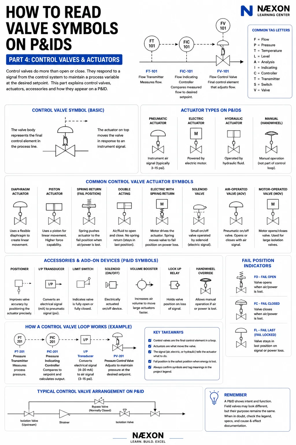
A simplified loop might look like:
FT-101 → FIC-101 → FV-101
Let’s break that down.
FT-101 — Flow Transmitter
Measures the process flow.
↓
FIC-101 — Flow Indicating Controller
Receives the measurement and compares it with the desired setpoint.
↓
FV-101 — Flow Valve
Changes position to influence flow.
The transmitter sees.
The controller decides.
The valve acts.
That is the basic idea behind a control loop.
Start With the Valve Body
A control valve still has a valve body.
Depending on the application, the actual valve could use a:
Globe-style body
Ball
Butterfly disc
Plug
or another control-valve design.
The body controls the process fluid.
But something has to move the valve.
That brings us to the actuator.
What Is an Actuator?
An actuator converts some form of energy into mechanical movement.
In simple terms:
The actuator moves the valve.
That energy might come from:
Instrument air
Electricity
Hydraulic pressure
or another source.
On the P&ID, the actuator is typically represented with additional symbology associated with the valve body.
Learning to separate the valve body from the actuator makes control-valve symbols much easier to understand.
Think:
Valve body = controls the fluid
Actuator = moves the valve
Pneumatic Actuators
Pneumatic actuators use compressed air to move the valve.
They are extremely common in process plants.
You may hear terms such as:
Air-operated valve
Pneumatic control valve
Diaphragm actuator
Piston actuator
Spring-return actuator
depending on the design.
A pneumatic actuator can receive a pneumatic control signal directly or operate through accessories such as an I/P transducer and positioner.
Diaphragm Actuator
A diaphragm actuator uses air pressure acting against a flexible diaphragm to create movement.
The actuator may also contain a spring.
The relationship between air pressure and spring force moves the valve stem.
A simplified concept is:
Air pressure → diaphragm moves → stem moves → valve position changes
If the actuator uses a spring-return design, that spring can also help determine what happens when instrument air is lost.
That becomes extremely important when discussing fail position.
Piston Actuator
A piston actuator uses pressure acting against a piston.
Compared with diaphragm designs, piston actuators can be useful where higher force or different stroke characteristics are required.
They may be:
Single acting
or
Double acting
A double-acting actuator typically uses pressure to move the actuator in both directions rather than depending solely on a spring for the return movement.
The important lesson for P&ID reading is simple:
When you recognize the actuator symbol, ask:
What energy source moves this valve?
Air-Operated Valve — AOV
You may encounter the abbreviation:
AOV
meaning:
Air-Operated Valve
This generally tells you that pneumatic energy operates the valve.
But don’t assume AOV tells you everything about its control function.
An air-operated valve could be used for:
On/off service
Isolation
Shutdown service
or potentially another application depending on the design.
Look at the surrounding instruments and signals.
The entire drawing tells you the function—not one abbreviation.
Motor-Operated Valve — MOV
Another common abbreviation is:
MOV
or:
Motor-Operated Valve
An electric motor drives the valve mechanism.
MOVs are commonly encountered where valves are:
Large
Remote
Difficult to operate manually
or need to be operated from a control system.
They may be used for:
Isolation
Process routing
Utility systems
Water systems
Large process valves
Remote operation
A motor-operated valve isn’t automatically the same thing as a continuously modulating control valve.
Many MOVs primarily open and close.
Others may be designed for positioning service.
Again:
Read the system.
Solenoid-Operated Valves
A solenoid converts an electrical signal into mechanical movement.
Solenoids are frequently used in control systems to switch pneumatic signals.
For example:
Control system electrical signal
↓
Solenoid valve changes position
↓
Instrument air is supplied or vented
↓
Actuator moves
↓
Process valve opens or closes
The solenoid may therefore be a relatively small component controlling a much larger valve.
On a detailed P&ID, understanding that signal path can explain exactly how an emergency or automatic valve operates.
Electric Actuators
Not every electrically operated valve uses a traditional large MOV arrangement.
Electric actuators can directly position valves using an electric motor or other electrically driven mechanism.
Depending on the application, they may provide:
Open/close operation
Modulating control
Position feedback
Remote operation
Local manual override
When interpreting the P&ID, identify both the valve and the actuator designation.
Hydraulic Actuators
Hydraulic actuators use pressurized hydraulic fluid to create movement.
They’re useful where significant force may be required.
Hydraulic actuation may be encountered on specialized valves, pipelines, large valves and certain high-force applications.
The basic reading method remains unchanged:
Valve body
- ●
Actuator
- ●
Signal
- ●
Accessories
=
Complete valve function
The Valve Positioner
A positioner is one of the most important accessories to understand.
Suppose the controller commands:
50% open
The actuator needs to move the valve to the corresponding position.
The positioner helps ensure that the valve actually reaches and maintains the requested position.
In simplified terms:
Controller asks for position
↓
Positioner compares command with actual valve position
↓
Positioner adjusts actuator
↓
Valve reaches commanded position
This improves valve-positioning accuracy and response.
I/P Transducer
You’ll frequently encounter:
I/P
This stands for:
Current-to-Pressure
or electrical-current-to-pneumatic conversion.
A common control system may use an electrical signal such as:
4–20 mA
while a pneumatic actuator or positioner operates using an air-pressure signal.
The I/P converts between the two.
Simplified:
4–20 mA electrical signal
↓
I/P transducer
↓
Pneumatic pressure signal
↓
Positioner / actuator
↓
Control valve
Once you understand that sequence, many control-loop drawings become much easier to follow.
Limit Switches
A limit switch can provide confirmation that a valve has reached a particular position.
For example:
Valve fully open
or
Valve fully closed
That feedback can be sent to a control or safety system.
This matters because commanding a valve to close doesn’t necessarily prove that the valve actually reached its closed position.
The control system may need confirmation.
Handwheel Overrides
Some actuated valves include a manual handwheel or other manual override.
This can allow manual operation under defined conditions.
On the P&ID, additional symbology may indicate that manual capability.
Don’t confuse the presence of a handwheel with an ordinary manual valve.
A valve can have:
An actuator
and
a manual override.
You need to read both pieces of the symbol.
Fail Open — FO
Now we get to one of the most important control-valve concepts.
FO = Fail Open
Under the specified failure condition, the valve is designed to move toward its open position.
Why would engineers want that?
Imagine a service where losing cooling would create a dangerous temperature increase.
Depending on the system design, engineers might prefer the cooling-medium valve to open when its operating energy is lost.
The safe failure position depends on the process.
Fail Closed — FC
FC = Fail Closed
Under the specified failure condition, the valve moves toward its closed position.
A simplified example could involve fuel supply.
If the control system loses its operating energy, shutting off fuel may be the safer state.
So a valve might be designed to fail closed.
But remember:
These are examples—not rules for identifying an actual valve.
Always use the project’s documentation.
Fail Last / Fail in Place
Some actuator arrangements are intended to remain approximately in their last position following certain failures.
You may encounter terminology such as:
FL — Fail Last
Fail in Place
Fail Locked
or project-specific abbreviations.
This is particularly important with double-acting actuators and systems using lock-up devices or stored energy.
Again, terminology varies.
Check the legend.
Normal Position Is Still Different From Fail Position
This deserves repeating.
Suppose a valve normally operates:
70% open
That tells you its normal operating condition.
Now suppose it loses instrument air and moves fully closed.
That is its:
Fail position.
These are not the same concept.
A valve can be:
Normally open and fail closed.
It can be:
Normally closed and fail open.
Or it can modulate continuously during normal operation and still have a defined failure position.
Don’t mix them together.
Reading the Instrument Letters
Let’s return to:
FT-101 → FIC-101 → FV-101
The first letter generally identifies the measured or initiating variable under common instrumentation conventions.
Examples include:
F — Flow
P — Pressure
T — Temperature
L — Level
Then additional letters describe the function.
Examples:
I — Indication
C — Control
T — Transmitter
S — Switch
V — Valve / final control element designation in common loop notation
So:
PT — Pressure Transmitter
PIC — Pressure Indicating Controller
PV — Pressure Valve
Likewise:
LT — Level Transmitter
LIC — Level Indicating Controller
LV — Level Valve
And:
TT — Temperature Transmitter
TIC — Temperature Indicating Controller
TV — Temperature Valve
The exact conventions must still be verified against the project’s legend.
Example 1 — Flow Control
Consider:
FT-101 → FIC-101 → FV-101
The process is flowing through a pipe.
FT-101 measures that flow.
FIC-101 compares the measured flow with the desired setpoint.
If flow is too low, the controller may command the valve to change position.
If flow is too high, it may command another adjustment.
FV-101 physically changes the restriction in the process line.
That is a closed control loop.
Example 2 — Pressure Control
Now consider:
PT-201 → PIC-201 → PV-201
PT-201 measures pressure.
PIC-201 compares measured pressure with its setpoint.
PV-201 changes position to influence pressure.
Notice the pattern?
The letters change.
The basic control philosophy doesn’t.
Measure → Decide → Act
Example 3 — Level Control
Imagine a vessel with:
LT-301 → LIC-301 → LV-301
LT-301 measures liquid level.
LIC-301 evaluates the level.
LV-301 adjusts flow entering or leaving the vessel, depending on the system design.
Again:
Measure → Decide → Act
Once you understand that pattern, you can start deciphering unfamiliar loops without memorizing every possible tag.
Signal Lines Matter
P&IDs use different line styles to represent different types of signals and connections.
Depending on the drawing standard, these may distinguish:
Pneumatic signals
Electrical signals
Data or software links
Hydraulic signals
Capillary connections
and other communication methods.
Don’t memorize one line pattern and assume it applies everywhere.
Use the legend.
The important concept is that a signal line connecting an instrument to a valve tells you:
These devices interact.
A Typical Control Valve Station
A control valve often isn’t installed by itself.
You may see an arrangement involving:
Upstream isolation valve
↓
Strainer or other component
↓
Control valve
↓
Downstream isolation valve
with a:
Bypass line
around the control valve.
Why?
The isolation valves may allow the control valve to be removed or maintained.
The bypass may provide an alternate process path under approved operating conditions.
But actual arrangements vary considerably by service and facility.
Don’t assume every control valve station will look identical.
Control Valves During Maintenance
Control valves introduce special considerations during shutdown and maintenance work because an actuator can move the valve without someone physically touching it.
Potential energy sources may include:
Instrument air
Electricity
Hydraulic pressure
Springs
Stored pneumatic pressure
Process pressure
A valve that appears stationary can still contain stored energy.
Facility lockout/tagout, isolation and maintenance procedures govern how that equipment is made safe.
For workers entering refinery and turnaround environments, the Næxon Refinery Turnaround Dictionary: 100 Terms Every Shutdown Worker Should Know provides additional explanations of common isolation, commissioning, shutdown and maintenance terminology.
How to Read Any Control Valve on a P&ID
When you encounter an actuated valve, use this sequence:
1. Identify the process line.
What is flowing through it?
2. Identify the valve body.
What type of valve is being used?
3. Identify the actuator.
Pneumatic? Electric? Hydraulic?
4. Find the valve tag.
FV? PV? LV? TV? Something project-specific?
5. Follow the signal line backward.
What device commands the valve?
6. Find the controller.
What process variable is being controlled?
7. Find the transmitter or sensor.
What actually measures the process?
8. Look for accessories.
Positioner? I/P? Solenoid? Limit switch?
9. Determine failure position.
FO? FC? FL? Another project designation?
10. Check the legend and specifications.
Never guess when the drawing provides a way to verify.
Stop Looking at the Valve by Itself
This is the major lesson from Part 4.
If you see:
FV-101
don’t stop at:
“That’s a control valve.”
Ask:
What measures the flow?
Where is the controller?
What signal operates the actuator?
What moves the valve?
What happens if that energy disappears?
What equipment is this valve controlling flow into or out of?
Those questions turn a symbol into a process.
From Valve Symbols to Control Philosophy
We’re now far beyond simply recognizing a gate valve.
Parts 1 through 4 have built progressively:
Part 1 — Valve Symbol Fundamentals
How to break a symbol into understandable pieces.
Part 2 — Manual Valves
How gate, globe, ball, butterfly and other valves differ.
Part 3 — Check Valves & Flow Direction
How directional valves prevent reverse flow.
Part 4 — Control Valves & Actuators
How valves interact with instrumentation and control systems.
Next we’re going to look at valves and devices whose primary job isn’t routine process control.
Their job is protection, pressure management and emergency response.
Coming Next
How to Read Valve Symbols on P&IDs — Part 5: Relief, Safety & Special Valves
Part 5 will cover:
Pressure Safety Valves — PSV
Pressure Relief Valves
Safety Relief Valves
Vacuum Relief Valves
Pressure Regulators
Back-Pressure Regulators
Emergency Shutdown Valves — ESDV
Blowdown Valves — BDV
and other special devices commonly encountered on industrial P&IDs.
We’ll also tackle one of the abbreviations that causes plenty of confusion:
PRV
Because depending on the drawing, company and context, PRV may not mean what you initially think it means.
And that’s exactly why learning to read the entire P&ID matters more than memorizing abbreviations.


