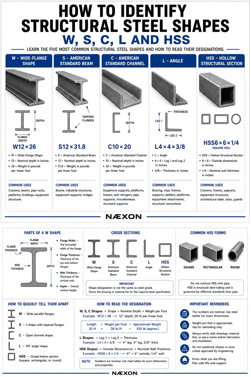
Structural steel can look like a collection of beams, channels, angles, and tubing when you first walk onto a jobsite. But those shapes are not random. Each one has a standardized designation that tells ironworkers, welders, fabricators, millwrights, and other trades what type of steel member they are working with and, in many cases, its approximate dimensions and weight.
Learning to recognize W, S, C, L, and HSS structural steel is one of the fundamentals of reading structural drawings and material lists. Once you understand what the letters and numbers mean, a designation such as W12×26 stops looking like a part number and starts giving you useful information immediately.
Why Structural Steel Has Different Shapes
Steel structures have to handle different kinds of forces. Some members carry loads vertically. Others span horizontally, resist bending, brace structures against movement, support equipment, or provide attachment points for other components.
Instead of manufacturing every structural member from scratch, the steel industry uses standardized shapes. Engineers can specify a particular shape and size on a drawing, and fabricators and erectors know what material is required.
Five of the most important designations to recognize are:
W — Wide-Flange Shape
S — American Standard Beam
C — American Standard Channel
L — Angle
HSS — Hollow Structural Section
The letter identifies the basic shape. The numbers following it provide additional information about its size.
W — Wide-Flange Shapes
The W shape is probably the structural steel member most workers recognize.
Looking at its cross-section, you will see two horizontal sections connected by a vertical section. The horizontal portions are called the flanges, while the vertical portion connecting them is called the web.
It looks roughly like this:
I
Because the flanges are relatively wide and generally parallel, the member is called a wide-flange shape.
You might see this on a drawing:
W12×26
This designation contains two important pieces of information.
The W tells you it is a wide-flange structural shape.
The 12 indicates the member’s nominal depth in inches.
The 26 indicates its nominal weight in pounds per linear foot.
Therefore, a W12×26 weighs approximately 26 pounds for every foot of beam.
A 20-foot piece would therefore have a nominal weight of:
26 × 20 = 520 lb
That quick calculation becomes extremely useful for material handling and preliminary rigging decisions, although an actual lift should always be planned using the correct material information and approved rigging procedures.
Wide-flange members are commonly used for structural columns, floor beams, pipe-rack steel, equipment structures, platforms, buildings, industrial facilities, and many other applications.
One important detail is that the first number is a nominal designation, not necessarily the exact measured depth of every W shape. Always use the appropriate steel dimensions table when exact dimensions are required.
Know the Parts of a Wide-Flange Beam
Understanding the terminology makes structural drawings much easier to follow.
The web is the vertical plate running through the center of the member.
The flanges are the horizontal sections at the top and bottom.
The overall vertical dimension is generally called the depth.
The horizontal dimension across the flange is the flange width.
The thickness of the web is the web thickness, while the thickness of each flange is the flange thickness.
These dimensions matter when laying out connections, drilling holes, welding attachments, installing clips, checking clearances, or fitting structural components.
S — American Standard Beam
An S shape is another I-shaped structural member.
For example:
S12×31.8
The S identifies it as an American Standard Beam. The 12 represents its nominal depth, while 31.8 represents its nominal weight in pounds per foot.
At first glance, an S beam can look very similar to a W shape. The important difference is the geometry of the flanges.
Wide-flange shapes generally have flange surfaces that are essentially parallel. Traditional S shapes have tapered flange surfaces.
That difference can matter when installing connections or hardware against the flange.
A common beginner mistake is assuming every I-shaped piece of structural steel is a W beam. It isn’t.
If the drawing specifies an S shape, do not automatically substitute a W shape simply because the overall dimensions appear similar. Their section properties and dimensions can be different.
C — American Standard Channel
A C shape is a structural channel.
Looking directly at the end, its cross-section resembles the letter C.
A designation might look like:
C10×20
The C identifies an American Standard Channel.
The 10 represents the nominal depth in inches.
The 20 represents the nominal weight in pounds per linear foot.
Channels have a web with two flanges extending from the same side. Because the section is open rather than symmetrical like a W shape, channels behave differently under load.
On industrial jobsites, channels are commonly found in equipment supports, platforms, frames, stair systems, miscellaneous structural supports, pipe-support assemblies, and fabricated structures.
Channels may also be installed back-to-back or combined with other steel members when required by the design.
L — Structural Angle
An L shape is what most tradespeople simply call angle iron or structural angle.
Viewed from the end, it forms an L.
Unlike W, S, and C designations, angle sizes are normally identified by their leg dimensions and thickness.
For example:
L4×4×3/8
This means the angle has:
4-inch leg × 4-inch leg × 3/8-inch thickness
Because both legs are the same size, this is an equal-leg angle.
But structural angles do not always have equal legs.
You could encounter something such as:
L6×4×1/2
That identifies an unequal-leg angle with a 6-inch leg, a 4-inch leg, and a 1/2-inch nominal thickness.
This is where orientation becomes important.
If a drawing calls for an unequal-leg angle, pay attention to which leg faces which direction. Rotating the angle incorrectly can put bolt holes, connections, or attached components in the wrong position.
Angles are extremely common for bracing, clips, supports, frames, equipment attachments, structural connections, platforms, ladders, miscellaneous steel, and fabricated assemblies.
HSS — Hollow Structural Section
HSS stands for Hollow Structural Section.
Instead of having an open cross-section like a W beam, channel, or angle, HSS is hollow.
It is commonly manufactured in square, rectangular, and round forms.
A square HSS designation might look like:
HSS6×6×1/4
This identifies a nominally:
6-inch × 6-inch hollow structural section with a 1/4-inch nominal wall designation.
A rectangular member could be identified as:
HSS8×4×1/4
That tells you the outside dimensions are nominally 8 inches by 4 inches with the specified nominal wall designation.
HSS is widely used for columns, frames, supports, equipment structures, architectural steel, racks, guards, and industrial structural systems.
There is an important caution when working with HSS: do not assume the nominal wall designation is the exact design wall thickness. HSS standards account for manufacturing tolerances and design thickness requirements. When engineering calculations, welding procedures, or critical fabrication depend on exact thickness, use the applicable specification and approved drawings rather than relying only on the designation.
Round HSS vs. Pipe
Round HSS deserves special attention because workers sometimes mistake it for ordinary pipe.
They may look similar, but they are designated for different purposes and governed by different product standards.
Pipe is traditionally identified using nominal pipe size and schedule, such as:
6-inch Schedule 40
Structural HSS uses an HSS designation based on structural dimensions and wall information.
The two should not automatically be treated as interchangeable.
If a structural drawing calls for HSS, install the material specified by the drawing rather than assuming a similar-looking piece of pipe is equivalent.
The Fastest Way to Recognize the Five Shapes
When you encounter structural steel in the field, first look at its cross-section.
A wide I-shaped member with wide, essentially parallel flanges is likely a W shape.
An I-shaped member with the characteristic tapered flange geometry may be an S shape.
A member shaped like an open C is a channel.
A member forming a 90-degree L is an angle.
A closed square, rectangular, or round structural tube is generally an HSS when specified as such on the structural documents.
But visual identification should only be your starting point. For actual fabrication or installation, verify the designation against the drawing, bill of material, piece mark, approved material documentation, or applicable steel table.
How to Read the Designation Without Getting Confused
There is a useful pattern to remember.
For W, S, and C shapes, a designation commonly follows:
Shape + nominal depth × weight per foot
For example:
W14×30
means a W shape with a nominal 14-inch depth weighing approximately 30 pounds per linear foot.
Angles work differently:
L4×3×3/8
means an angle with 4-inch and 3-inch legs and a 3/8-inch nominal thickness.
HSS uses outside dimensions and a nominal wall designation, such as:
HSS6×4×1/4
Once you understand which numbering system belongs to which shape, structural drawings become much easier to interpret.
Don’t Measure a Beam and Guess Its Designation
Suppose you measure a structural beam and determine that it is roughly 12 inches deep.
That does not automatically make it a W12 of a particular weight.
Many shapes can have similar overall depths while having different flange widths, flange thicknesses, web thicknesses, weights, and structural properties.
A W12×26 and another W12 member may belong to the same nominal depth family while having significantly different weights and dimensions.
That difference represents real steel.
Heavier members generally contain more cross-sectional area, and their structural properties can be substantially different.
This is why the complete designation matters.
Why the Weight-Per-Foot Number Is So Useful
The second number in W, S, and C designations gives field workers a quick way to estimate member weight.
Suppose a drawing calls for:
W18×35
and the member is 24 feet long.
Calculate:
35 lb/ft × 24 ft = 840 lb
The member’s nominal calculated weight is approximately 840 pounds, before considering attached plates, connections, hardware, or other components.
For a fabricated assembly, those additions can significantly increase total weight. Use the documented assembly weight or an approved lift calculation when one is available.
Understanding the designation therefore isn’t useful only for identifying material. It can help you understand what you are dealing with before the member ever leaves the ground.
Structural Steel on Drawings
Structural drawings often use these designations beside member lines rather than spelling everything out.
You might see:
W12×26
C8×11.5
L3×3×1/4
HSS4×4×1/4
An experienced worker can immediately translate those markings into physical steel shapes.
That skill becomes especially valuable when matching piece marks, staging material, laying out connections, checking deliveries, fabricating supports, or identifying that the wrong member has been sent to the work area.
Shape Designation Is Not the Same as Steel Grade
Another important distinction is that shape and material grade are separate pieces of information.
Knowing that something is a W12×26 tells you its structural shape and nominal weight. It does not, by itself, tell you everything about the steel’s material specification.
The drawing and project specifications may separately identify the required steel standard or grade.
That matters because two members with the same physical shape designation are not automatically acceptable substitutes if their material requirements differ.
On engineered work, never assume that steel is interchangeable simply because it measures the same.
Why Tradespeople Should Know This
You do not have to be a structural engineer to benefit from understanding structural steel.
An ironworker may need to identify the correct beam before erection. A welder may need to understand exactly what member an attachment is being welded to. A millwright may be installing equipment on an HSS frame. A pipefitter may be fabricating or installing supports attached to structural channels or beams.
Even when structural steel isn’t your primary trade, it surrounds industrial work.
Pipe racks, platforms, equipment structures, access systems, supports, buildings, and refinery structures are filled with standardized steel shapes.
Being able to look at W12×26, C10×20, L4×4×3/8, or HSS6×6×1/4 and understand what the designation is telling you is another step toward being able to read the job instead of simply following it.
The letters tell you the family of structural shape.
The numbers tell you important information about its size, weight, or wall designation.
Learn those patterns and a structural drawing starts becoming a lot less mysterious.


