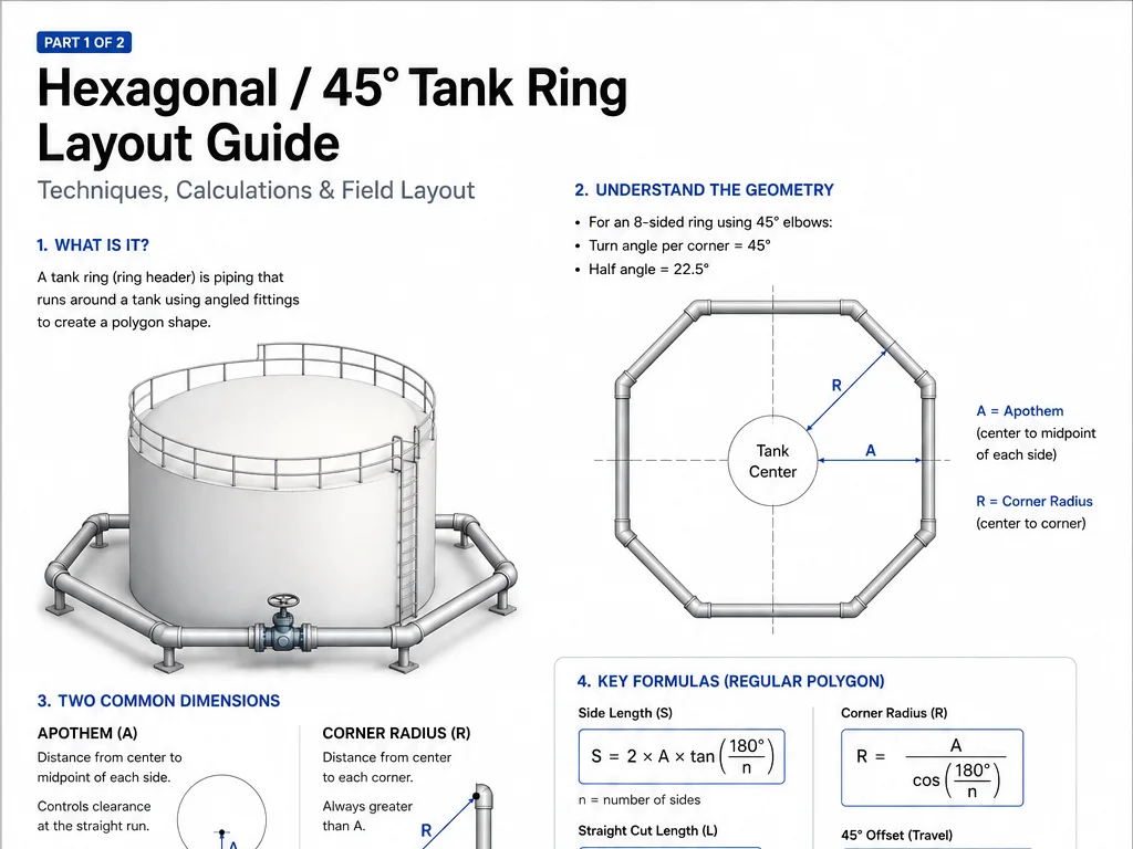
A tank ring header is piping routed around a tank, vessel, column, or other large piece of equipment. Instead of forming one continuous circular bend, the ring can be fabricated from straight pipe connected with elbows, creating a polygon around the equipment.
You may hear workers call it a tank ring, ring header, hex ring, octagon, polygon ring, or ring main, depending on the job.
The concept looks simple from above. The fabrication is not.
To make one close correctly, a pipefitter has to control tank center, pipe centerline radius, clearance, number of sides, fitting angles, fitting takeoffs, straight-piece lengths, orientation, elevation, branch clocking, and accumulated error.
The most important rule is:
Do all layout from the pipe centerline unless the drawing specifically tells you otherwise.
Hexagon vs. 45° Ring: Know the Difference
This is the first thing to understand.
A true regular hexagon has six sides.
To make one complete revolution:
360° ÷ 6 = 60°
Therefore, every corner of a regular hexagonal pipe ring changes direction by 60°.
A regular ring constructed with 45° changes of direction naturally has eight sides:
360° ÷ 45° = 8 sides
That makes it an octagonal ring, even though workers in the field may loosely call polygon-shaped tank piping a “hex.”
So:
6 sides = 60° turn at each corner
8 sides = 45° turn at each corner
If the job specifically says to use 45° elbows around a tank and all the sections are symmetrical, you’re most likely dealing with an eight-sided polygonal ring.
Always follow the approved drawing rather than the nickname used in the field.
Start With the Tank Centerline
Everything should begin from a known center.
Imagine a tank with an outside diameter of:
20’-0”
Its radius is:
20’ ÷ 2 = 10’-0”
Now suppose the required distance from the outside of the tank shell to the pipe centerline is:
2’-0”
The centerline of the straight portions of the ring would therefore be:
10’ + 2’ = 12’-0” from tank center
This 12-foot measurement is extremely important.
But there’s another detail.
Where on the polygon does that 12-foot dimension apply?
The middle of a straight side?
Or the corner?
Those produce different-sized rings.
Apothem vs. Corner Radius
For polygon layout, there are two dimensions every fitter should understand.
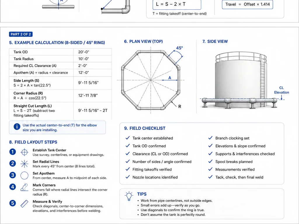
The apothem is the perpendicular distance from the center of the polygon to the center of a straight side.
The circumradius is the distance from the center to a corner.
For tank rings, the apothem is especially useful because the middle of each straight section is normally the portion closest to the tank.
Imagine an octagonal pipe ring surrounding a round tank.
If the pipe centerline at the middle of each straight section must remain:
12’-0” from tank center
then:
Apothem = 12’-0”
The corners will naturally be farther away.
Calculating the Straight-Side Geometry
For any regular polygon:
Side Length = 2 × Apothem × tan(180° ÷ Number of Sides)
For an eight-sided ring:
180° ÷ 8 = 22.5°
Therefore:
Side = 2 × Apothem × tan(22.5°)
Since:
tan(22.5°) ≈ 0.4142
with a 12-foot apothem:
Side = 2 × 12 × 0.4142
Side ≈ 9.941 feet
Converting the decimal:
0.941 × 12 = 11.292 inches
So the theoretical side is approximately:
9’-11 5/16”
This is the theoretical distance from one corner centerline intersection to the next.
It is not automatically your straight pipe cut length.
That’s the next calculation.
Fitting Takeoff Must Be Removed
Your theoretical corner exists where two pipe centerlines would intersect.
The actual elbow occupies space on both sides of that intersection.
Therefore:
Cut Length = Theoretical Side − Takeoff #1 − Takeoff #2
If identical elbows are installed on both ends:
Cut Length = Theoretical Side − 2 × Elbow Takeoff
Suppose the theoretical side is:
9’-11 5/16”
And assume, strictly for demonstration, that the applicable center-to-end dimension is:
6”
Then:
6” + 6” = 12”
Therefore:
9’-11 5/16” − 1’-0”
= 8’-11 5/16”
That would be the straight-piece cut length for that hypothetical fitting dimension.
Do not use 6 inches as a field takeoff unless it matches the fitting you’re actually installing.
Actual center-to-end dimensions depend on pipe size, fitting standard, elbow type and manufacturer. Piping references likewise treat fitting dimensions as specific dimensions that must be incorporated into the run rather than guessed. (studylib.net)
Why 22.5° Shows Up in a 45° Ring
This confuses some new fitters.
You’re using 45° turns, so why are you calculating with 22.5°?
Because you’re splitting the corner angle in half.
45° ÷ 2 = 22.5°
Draw a line from the tank center through the middle of one side and another through the corner. That creates the right triangle used to solve half of the polygon section.
That’s where:
tan(22.5°)
comes from.
Understanding this triangle is much better than simply memorizing a multiplier because you can then solve unusual layouts when the dimensions change.
Calculating the Distance to the Corners
Suppose your apothem remains:
12’-0”
For an octagon:
Corner Radius = Apothem ÷ cos(22.5°)
cos(22.5°) ≈ 0.92388
Therefore:
12 ÷ 0.92388 ≈ 12.988 feet
That’s approximately:
12’-11 7/8”
So notice what happens.
At the middle of the straight section:
12’-0” from tank center
At the theoretical corner:
approximately 12’-11 7/8” from tank center
The corner sticks out almost another foot.
Nothing is wrong.
That’s simply polygon geometry.
Calculating Clearance From the Tank
Now assume:
Tank OD = 20’-0”
Tank radius = 10’-0”
Pipe-centerline apothem = 12’-0”
Minimum centerline clearance at the middle of a straight section is:
12’ − 10’ = 2’-0”
But that’s centerline-to-shell clearance.
If you need actual clearance between the tank shell and the outside surface of the pipe, you also have to account for the pipe’s outside radius.
For example, if the pipe OD were 10.75”:
Pipe radius = 5.375”
Then approximately:
24” − 5.375”
= 18.625”
or:
1’-6 5/8”
of theoretical shell-to-pipe outside clearance at the closest portion of the straight run.
This distinction matters when checking access, insulation and interferences.
Don’t Confuse NPS With Actual Pipe OD
A common field-layout mistake is treating nominal pipe size as the actual outside diameter.
They aren’t always the same number.
When clearance calculations depend on the physical outside surface of the pipe, use the actual OD specified for that pipe—not merely its nominal designation.
The same principle applies when laying out saddles, laterals and branch intersections: actual pipe diameters are required for accurate geometric layout. (Construction Manuals)
Field Layout Technique
Once the calculations are complete, establish the geometry physically.
First establish the true center of the tank from approved survey information, equipment centerlines, grid lines, foundation coordinates, or other reliable control.
Don’t simply eyeball the shell.
For an eight-sided ring, establish radial reference lines every:
45°
That gives:
0°
45°
90°
135°
180°
225°
270°
315°
These lines establish the repeating geometry.
Next, establish the required pipe centerline distance.
If the apothem is 12 feet, each straight section must remain tangent to an imaginary 12-foot-radius centerline circle.
You now have a geometric framework for locating every side and corner.
An Easy Field Method Using Opposing Centerlines
Establish two perpendicular axes through the tank center.
Think:
North–South
and
East–West
Then establish the 45° diagonals between them.
You now have eight equally spaced radial references.
Measure from the center rather than walking around the tank measuring one piece from the previous piece.
That’s important.
If every measurement originates from the previous fitting, every little error follows you around the tank.
If measurements originate from a common known center, errors become easier to identify.
Fabricate in Sections
Don’t automatically weld the entire ring into one assembly.
Large rings may be easier to fabricate as:
halves
quarters
or manageable spool sections.
The fabrication plan depends on pipe size, weight, available lifting equipment, field access, transportation, support locations and the approved construction procedure.
For an eight-sided ring, quarter sections can be particularly convenient geometrically because each quarter represents:
90° of the ring
or:
two 45° direction changes
But the actual spool breaks should be chosen according to the project’s drawings and fabrication requirements.
Tack Before Final Welding
One of the easiest ways to ruin a ring is to completely weld every joint as you travel around it without repeatedly checking geometry.
Welding introduces shrinkage.
Small angular errors also compound.
A better approach, where the approved fabrication procedure permits it, is to:
Fit.
Tack.
Measure.
Check diagonals.
Check centerline radius.
Check elevation.
Check rotation.
Then continue.
Final welding should follow the project’s approved welding sequence and WPS.
The Closing Piece Tells the Truth
The last section of the ring is where every previous mistake shows up.
Imagine an eight-sided ring where every theoretical side is only:
1/8” too long
Eight errors of 1/8” represent:
1” of accumulated linear discrepancy
Angular error can create even greater problems.
If every 45 is slightly over- or under-rotated, the final ends can miss each other even though every individual straight piece was cut to the same length.
That’s why:
“Every piece is the same”
doesn’t necessarily mean:
“The ring is correct.”
Check the Diagonals
Side dimensions alone cannot prove a polygon is correctly shaped.
Measure between corresponding points across the assembly.
Opposite diagonal measurements should agree where symmetry requires them to.
If one diagonal is longer than the corresponding opposite measurement, the ring may be racked.
Checking diagonals before final welding gives you a chance to correct the geometry.
Check Center-to-Corner Measurements
Another powerful check is measuring from the established tank center to each theoretical corner.
For a regular octagon, those dimensions should agree.
Using our previous example, each theoretical corner should be approximately:
12’-11 7/8” from center
If seven corners are correct and one is significantly different, you’ve found a problem before closing the ring.
Don’t Forget Elevation
Everything we’ve calculated so far is primarily plan-view geometry.
Real piping exists in three dimensions.
You also need to control:
Pipe centerline elevation
Tank nozzle elevation
Support elevation
Required slope
Drain points
High points
Valve orientation
Branch elevations
Tie-in elevation
A beautiful octagon viewed from above can still be completely wrong if one quadrant is several inches high.
Think:
X — horizontal position
Y — horizontal position
Z — elevation
All three matter.
Branches and Nozzles Need Clocking
Ring headers frequently feed or collect from multiple connections.
You might have:
tees,
olets,
valves,
drains,
vents,
spray nozzles,
instrument connections,
equipment branches,
or additional headers.
These connections need accurate clocking.
Establish a consistent pipe reference.
For example:
Top center = 0°
Then mark every branch from that reference rather than eyeballing it.
The same geometric discipline is used in other pipe layout work, including angled branch/header connections where centerlines and circumference divisions establish the cut geometry. (Scribd)
The Tank Nozzle May Control Everything
Suppose you’ve calculated the perfect octagon.
Then you discover the tank nozzle lands directly at an awkward point near an elbow.
That’s why fixed tie-ins should be identified before production fabrication.
Find:
Tank nozzles
Existing piping
Pump connections
Valves
Pipe rack tie-ins
Expansion joints
Structural penetrations
Required support locations
The orientation of the polygon around the tank may need to be established from one of these fixed points.
Don’t build a mathematically beautiful ring that doesn’t connect to the plant.
Unequal Tank-Ring Sections
Not every ring will be a perfect regular polygon.
Sometimes interference forces one section outward.
Sometimes a nozzle controls one corner.
Sometimes structural steel prevents a symmetrical route.
Sometimes several lines run around the vessel at different spreads.
At that point, stop treating the entire assembly as one regular octagon.
Break the piping into individual triangles and offsets.
Solve each section from known centerline points.
The same principles used for 45° offsets and equal/unequal spread piping around vessels apply to more complicated layouts; advanced pipefitting training specifically treats vessel offsets and tank-coil fabrication as geometric layout problems. (Scribd)
Useful 45° Geometry
For ordinary 45° pipefitting work, remember:
A 45° right triangle has equal legs.
If your offset is:
24”
the advance is also:
24”
The diagonal travel is:
24 × √2
≈ 33.94”
or approximately:
33 15/16”
The commonly used multiplier is approximately:
1.414
So:
Travel = Offset × 1.414
This becomes useful when the tank-ring design incorporates offsets, jogs, tie-ins, or elevation changes outside the regular polygon.
Example: Complete 45° Tank Ring Calculation
Let’s put the basic process together.
Assume:
Tank OD = 20’-0”
Required tank-shell-to-pipe-centerline clearance at the middle of each straight = 2’-0”
Ring = 8 equal sides
Direction change = 45° per corner
First calculate tank radius:
20’ ÷ 2 = 10’
Add required centerline clearance:
10’ + 2’ = 12’ apothem
Now calculate theoretical side:
2 × 12 × tan(22.5°)
≈ 9.941’
≈ 9’-11 5/16”
Next calculate corner radius:
12 ÷ cos(22.5°)
≈ 12.988’
≈ 12’-11 7/8”
Now obtain the verified center-to-end dimensions for the actual 45° elbows being installed.
If that dimension is T, then:
Straight Cut Length = 9’-11 5/16” − 2T
Do that calculation using the actual approved fitting dimensions.
Then verify the complete layout against the tank, nozzle locations, supports, interferences and elevations before production cutting.
Quick Formula Sheet
For a regular polygon:
Turn Angle = 360° ÷ Number of Sides
Half Angle = 180° ÷ Number of Sides
Side = 2 × Apothem × tan(Half Angle)
Corner Radius = Apothem ÷ cos(Half Angle)
For an eight-sided 45° ring:
Turn Angle = 45°
Half Angle = 22.5°
Side = 2a × tan(22.5°)
Corner Radius = a ÷ cos(22.5°)
For straight pipe between identical elbows:
Cut Length = Theoretical Side − 2 × Fitting Takeoff
For a conventional 45° offset:
Travel ≈ Offset × 1.414
Field Checklist Before You Cut
Before cutting the first production piece, make sure you know:
Tank center
Actual tank OD
Required pipe clearance
Whether clearance is to pipe centerline or pipe OD
Number of polygon sides
Required corner angle
Pipe size and actual OD
Actual fitting center-to-end dimensions
Ring centerline elevation
Fixed nozzle locations
Branch clocking
Support locations
Interferences
Spool-break locations
Welding/fabrication requirements
Then calculate.
Then lay it out.
Then verify it again.
Measure the ring from known control—not from the mistake you made on the previous piece.
The Pipefitter’s Rule for Tank Rings
A tank ring is really three problems happening at once.
Geometry: Will the polygon close?
Fabrication: Have the fittings, takeoffs, welds and spool dimensions been accounted for?
Field fit: Will the finished assembly actually fit around the real equipment and connect where it’s supposed to?
A good fitter solves all three before turning a pile of pipe and fittings into an expensive problem.
For a symmetrical ring, remember the simplest distinction:
Six equal sides → 60° turns → regular hexagon.
Eight equal sides → 45° turns → regular octagon.
Once you understand why, you don’t have to memorize the entire layout. You can rebuild the calculation from the geometry whenever you need it.
Continue Learning
This tank-ring layout brings together several core pipefitting skills. Continue through the Næxon Learning Center with related lessons on 45° pipe runs, rolling offsets, piping isometrics, flange bolt-hole rotation and clocking, pipefitter math, saddle layout, fitting takeoffs, P&IDs, and pipe centerline calculations.
If you’re using these skills in the field or looking for your next shutdown, turnaround, refinery, power-plant, or industrial construction project, visit Næxon Careers for current skilled-trade opportunities.


