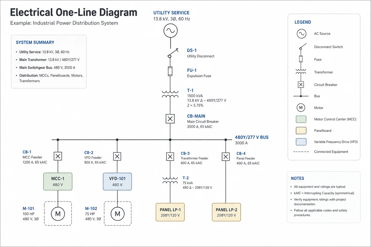
An electrical one-line diagram, also called a single-line diagram or SLD, is one of the most important drawings an industrial electrician can learn to read. It shows how electrical power moves through a facility—from the utility or generator, through transformers and switchgear, and eventually to distribution panels, motor control centers, motors, and other loads.
Unlike a wiring diagram, a one-line diagram does not show every individual conductor. Three-phase power may have three phase conductors, but the drawing represents the circuit with one line. That simplification allows an electrician to understand an entire power-distribution system without looking at thousands of individual wires.
The key to reading one-lines is simple:
Start at the power source and follow the power downstream.
What Does “One-Line” Mean?
Imagine a three-phase feeder containing:
Phase A
Phase B
Phase C
Instead of drawing all three conductors across an entire facility, the engineer draws one line representing the three-phase circuit.
Conceptually:Actual three-phase circuit: A ───────────────── B ───────────────── C ───────────────── One-line representation: ───────────────────
The one line doesn’t mean there is physically one conductor. It represents the electrical circuit as a simplified system.
Neutral and grounding information may be shown separately when it is important to the design.
Start With the Power Source
When opening a one-line diagram for the first time, locate the source.
Common sources include:
Utility service
Generator
Transformer
Substation
UPS system
Battery system
A simplified industrial distribution system might look like:UTILITY │ │ TRANSFORMER │ │ MAIN SWITCHGEAR │ ├───────────────┐ │ │ MCC-1 PANEL LP-1 │ MOTOR
Immediately, you can see the hierarchy of the electrical system.
Utility power enters the transformer. The transformer feeds the main switchgear. The switchgear distributes power to an MCC and a panel. The MCC supplies a motor.
That basic ability to trace power is the foundation of reading one-line diagrams.
Step 1: Find the Voltage
Voltage levels are some of the first information you should identify.
Industrial facilities may contain systems such as:
13.8 kV
4.16 kV
480 V
208Y/120 V
240 V
Voltage often changes when power passes through a transformer.
For example:
13.8 kV → Transformer → 480Y/277 V
The transformer steps the voltage down from medium voltage to a utilization or distribution voltage.
Another transformer downstream might produce:
480 V → Transformer → 208Y/120 V
That lower voltage can supply receptacles, lighting, controls, and other loads.
When tracing a one-line, keep track of the voltage every time you cross a transformer.
Step 2: Identify the Transformer
Transformers are critical landmarks on one-line diagrams.
A transformer changes voltage and may also establish grounding and system configuration.
You might see information similar to:
T-101
1500 kVA
13.8 kV – 480Y/277 V
Z = 5.75%
Each piece of information means something.
T-101 is the equipment identification number.
1500 kVA is the transformer’s apparent-power rating.
13.8 kV is the primary voltage.
480Y/277 V is the secondary voltage.
Z = 5.75% represents transformer impedance.
Transformer impedance becomes especially important when engineers calculate available fault current.
Step 3: Identify the Main Breaker
After the transformer, power commonly enters switchgear or a switchboard through a main breaker.
You might see:
MAIN CB — 2000 A
This tells you the main circuit breaker is rated for 2,000 amperes, subject to the other ratings and notes on the drawing.
The breaker symbol and annotations may also provide:
Frame size
Trip rating
Interrupting rating
Voltage rating
Protective functions
Equipment designation
Never assume a number next to a breaker represents only one characteristic. Always check the drawing legend and equipment schedule.
Step 4: Understand the Bus
Inside switchgear, switchboards, MCCs, and panelboards, power is distributed through a bus.
A bus may appear as a heavy horizontal or vertical line.
Example: MAIN BREAKER │ │ ═════════════╪═════════════ 480 V BUS │ │ │ CB CB CB │ │ │ MCC XFMR LOAD
The heavy line represents the bus.
Individual feeder breakers connect to it and distribute power downstream.
If the bus is labeled:
480 V — 3000 A BUS
you now know both its nominal voltage and its current rating as shown by the design.
Step 5: Follow the Feeders
A feeder carries power from one distribution point to another.
For example:
Main Switchgear → MCC-1
or:
Switchboard → Panelboard
or:
Substation → Transformer
Feeder information may contain conductor and raceway details.
You might see something similar to:
3#4/0 Cu + 1#4 G, 2”C
The exact notation varies by engineering company, but this could indicate three 4/0 copper phase conductors, an equipment grounding conductor, and a 2-inch conduit.
This is where the drawing legend is essential.
Never assume every engineering drawing uses identical abbreviations.
Step 6: Understand Circuit Breakers
Circuit breakers protect conductors and equipment against overcurrent conditions according to the system design.
On a one-line, you may encounter:
MCCB — Molded Case Circuit Breaker
ICCB — Insulated Case Circuit Breaker
LVPCB — Low-Voltage Power Circuit Breaker
VCB — Vacuum Circuit Breaker
Different breakers are used at different voltage levels and applications.
A breaker might be labeled:
800 AF / 600 AT
Commonly:
AF = Ampere Frame
AT = Ampere Trip
That means the breaker may have an 800-amp frame with a 600-amp trip rating/configuration.
Again, confirm terminology against the project legend and breaker documentation.
Step 7: Recognize Disconnect Switches
A disconnect switch provides a means of isolating equipment.
You may see disconnects near:
Motors
Transformers
HVAC equipment
Process equipment
Machinery
A motor circuit might conceptually look like:MCC │ BREAKER │ FEEDER │ DISCONNECT │ MOTOR
That diagram tells you there is an isolation point between the distribution equipment and the motor.
Whether a disconnect can safely interrupt load current depends on its rating and application. A disconnect should never automatically be treated as a circuit breaker.
Step 8: Find the Motor Control Center
A Motor Control Center, or MCC, is one of the most common pieces of equipment in industrial facilities.
An MCC distributes power to multiple motors and other loads.
A simplified one-line might show:480 V SWITCHGEAR │ │ MCC-1 │ ┌─────┼─────┐ │ │ │ M-101 M-102 M-103
The MCC could contain starters, circuit breakers, fuses, contactors, overload protection, variable-frequency drives, and control equipment depending on the system.
Each motor generally has an equipment tag.
For example:
P-101A
could identify a pump motor associated with Pump 101A.
Equipment tagging systems vary from plant to plant.
Step 9: Recognize Motor Information
A motor may be identified with information such as:
M-101
100 HP
480 V
3Ø
This tells you:
Motor identification: M-101
Horsepower: 100 HP
Voltage: 480 V
Phase: Three phase
Other drawings or schedules may provide:
Full-load current
RPM
Efficiency
Service factor
Enclosure
NEMA design
Starter type
VFD information
The one-line normally provides only the information necessary to understand the power-distribution system.
Step 10: Recognize a VFD
A Variable Frequency Drive, or VFD, controls motor speed by changing the frequency and voltage supplied to the motor.
A simplified circuit might look like:480 V MCC │ BREAKER │ VFD │ MOTOR
When troubleshooting, the VFD becomes an important dividing point.
You have:
Line side
and
Load side
The line side receives incoming power.
The load side supplies controlled output to the motor.
Testing procedures around VFDs require additional care because their outputs are electronically generated and conventional meter readings may not always behave like measurements on a simple sinusoidal utility supply.
Step 11: Understand Fuses
Fuses may appear upstream of transformers, motors, capacitors, drives, or other equipment.
Their purpose is overcurrent protection.
A one-line may identify:
Fuse rating
Fuse class
Interrupting rating
Equipment protected
Never replace a fuse simply because another fuse physically fits.
Fuse class, voltage, current rating, time-current characteristics, and interrupting capability all matter.
Step 12: Understand Grounding Symbols
Grounding information is extremely important on one-line diagrams.
You may see symbols representing:
Equipment grounding
System grounding
Grounding electrode connections
Transformer neutral grounding
A grounded transformer secondary might conceptually show:TRANSFORMER │ NEUTRAL │ ⏚
This indicates that the system has a grounded point, subject to the exact drawing details.
Different systems may use solid grounding, resistance grounding, impedance grounding, or other grounding arrangements.
Never assume every industrial electrical system is grounded the same way.
Step 13: Understand Grounded-Wye Systems
A common designation is:
480Y/277 V
The Y indicates a wye-connected system.
The system provides approximately:
480 V phase-to-phase
and:
277 V phase-to-neutral
The relationship is:
Line Voltage = Phase Voltage × √3
Therefore:
277 × 1.732 ≈ 480 V
The same relationship explains:
120 × 1.732 ≈ 208 V
which gives us the familiar:
208Y/120 V
system.
Step 14: Recognize Current Transformers
A Current Transformer, commonly abbreviated CT, produces a reduced current proportional to the primary current so metering and protective devices can monitor high-current circuits.
You might see:
CT 1200:5
This means that under the transformer’s specified ratio conditions:
1200 A primary corresponds to 5 A secondary.
The ratio is:
1200 ÷ 5 = 240:1
So if the secondary current were 2.5 A under ideal ratio conditions:
2.5 × 240 = 600 A primary
CT circuits require special handling. An energized CT secondary should not be casually opened because hazardous voltage can develop.
Step 15: Recognize Potential or Voltage Transformers
A Potential Transformer (PT) or Voltage Transformer (VT) reduces system voltage to a lower value suitable for metering, relaying, or control equipment.
For example:
13,800 V → PT → 120 V
Protective relays and meters can then monitor a proportional representation of the higher system voltage.
CTs measure current indirectly.
PTs/VTs measure voltage indirectly.
Step 16: Understand Protective Relays
Medium- and high-voltage one-line diagrams frequently show protective relay functions.
You may encounter ANSI device numbers such as:
50 — Instantaneous Overcurrent
51 — Time Overcurrent
27 — Undervoltage
59 — Overvoltage
81 — Frequency
87 — Differential Protection
For example:
50/51
means the protective scheme includes instantaneous and time-overcurrent functions.
These numbers appear repeatedly in substations, switchgear, generator systems, and large industrial power systems.
Step 17: Understand Normally Open Ties
Large electrical systems may have multiple buses connected through a tie breaker.
Example:SOURCE A SOURCE B │ │ MAIN A MAIN B │ │ ═══ BUS A ═══ TIE CB ═══ BUS B ═══
The tie breaker may normally be open.
If one source is unavailable, an approved switching scheme may allow one source to supply additional sections of the system.
This arrangement can improve system flexibility and reliability.
However, closing a tie breaker without understanding system conditions can create extremely dangerous situations, including paralleling sources that were not designed or synchronized to operate together.
Step 18: Look for Equipment Ratings
One-line diagrams aren’t merely maps.
They also communicate electrical ratings.
Look for information such as:
Voltage
Current
kVA
MVA
Horsepower
Breaker rating
Fuse rating
Bus rating
Transformer impedance
Available fault current
Short-circuit rating
These numbers tell electricians and engineers what the equipment is designed to handle.
Step 19: Understand Available Fault Current
A one-line may show calculated short-circuit current at different buses.
For example:
Available Fault Current = 38 kA
That means the calculated prospective fault current at that point may reach approximately 38,000 amperes, subject to the study assumptions.
Equipment connected at that location must have appropriate interrupting and short-circuit ratings.
A breaker capable of interrupting only 22 kA would not automatically be acceptable at a location where 38 kA is available.
Fault-current calculations are one reason transformer impedance, conductor impedance, source characteristics, and equipment ratings matter so much.
Step 20: Read the System From Top to Bottom
When you’re handed an unfamiliar one-line, don’t try to understand every symbol immediately.
Trace one path.
For example:
Utility
↓
13.8 kV Service
↓
Main Medium-Voltage Switchgear
↓
13.8 kV / 480 V Transformer
↓
480 V Switchgear
↓
Feeder Breaker
↓
MCC
↓
Motor Starter or VFD
↓
Motor
Once you understand that path, trace another feeder.
Then another.
Eventually the entire electrical system begins to make sense.
One-Line Diagram vs. Wiring Diagram
These drawings serve different purposes.
A one-line diagram shows the overall electrical power-distribution system.
A wiring diagram shows actual electrical connections.
A schematic shows how a control or electrical circuit functions logically.
A panel schedule identifies circuits and loads associated with a panel.
A cable schedule identifies cable characteristics and routing information.
A loop diagram shows instrumentation and control-loop connections.
An industrial electrician often uses several of these drawings together.
The one-line tells you where the power comes from and where it goes.
The wiring drawings tell you how the equipment is actually connected.
A Simple Example
Consider this system:UTILITY — 13.8 kV │ │ TRANSFORMER T-1 13.8 kV / 480Y/277 V │ │ MAIN CB 2000 A │ ══════════════════ 480 V BUS ══════════════════ │ │ CB CB │ │ MCC-1 XFMR T-2 │ 480 → 208Y/120 VFD │ │ PANEL LP-1 M-101 100 HP
Without seeing a single individual conductor, you can already determine the basic system.
Utility power enters at 13.8 kV.
Transformer T-1 steps it down to 480Y/277 V.
A 2000 A main breaker supplies the 480 V bus.
One feeder supplies MCC-1.
The MCC feeds a VFD.
The VFD controls Motor M-101.
Another feeder supplies Transformer T-2.
T-2 steps 480 V down to 208Y/120 V.
That transformer supplies Panel LP-1.
That is the power of a one-line diagram: a large electrical distribution system can be understood from a relatively simple drawing.
Never Assume the Drawing Is the Current Field Condition
This is especially important in older industrial facilities.
Equipment gets replaced.
Feeders get rerouted.
Breakers get changed.
Temporary power becomes permanent.
Panels get added.
Old equipment gets abandoned.
The drawing may show what was designed or what existed when the drawing was last revised—not necessarily what is physically energized today.
Always check the drawing’s:
Revision number
Revision date
Status
Engineering notes
As-built information
and applicable plant documentation.
For actual electrical work, the drawing must be combined with proper identification, testing, lockout/tagout procedures, PPE requirements, and the facility’s electrical-safety program.
The Fastest Way to Learn One-Lines
Don’t start by memorizing hundreds of electrical symbols.
Learn the major equipment first:
Source → Transformer → Breaker → Bus → Feeder → MCC/Panel → Load
Then learn what each piece of equipment does.
After that, learn the ratings and protection information surrounding those symbols.
Eventually, when you look at a one-line, you stop seeing lines and symbols.
You see power moving through the plant.
That is the real skill.
Continue through the Næxon Learning Center with related lessons on electrical symbols, conduit bending, motor circuits, transformers, MCCs, three-phase power, instrumentation loop diagrams, and industrial troubleshooting.


