Næxon Learning Center | Ironworker Fundamentals
Setting a structural steel column starts long before the crane picks it up. If the anchor bolts are out of position, the base plate is oriented incorrectly, or the column centerline does not match the building grid, the problem eventually shows up during erection—and by that point, correcting it can become expensive.
That is why understanding base plates, anchor bolts, grid lines, centerlines, elevations, and field verification is fundamental knowledge for structural ironworkers.
A column may weigh thousands of pounds, but its final position can depend on measurements taken to fractions of an inch.
This lesson explains how those measurements relate to one another and how an ironworker can systematically verify the layout before a column is permanently set.
Start With the Building Grid
Most structural layouts begin with a grid system.
Instead of locating every column independently from the edge of a slab or foundation, the structural drawings establish reference lines running through the building.
One direction may use numbers:
1 — 2 — 3 — 4 — 5
The perpendicular direction may use letters:
A — B — C — D — E
Where two grid lines intersect, you have a known coordinate.
For example:
Grid B-4
means the intersection of Grid B and Grid 4.
A structural column might be centered directly on that intersection. Another column may be intentionally offset from it. The structural drawings tell you which condition applies.
This distinction matters.
Never assume that the center of every base plate equals the intersection of the structural grid lines. Verify the dimensions shown on the drawings.
Establish the Column Centerlines
Once the correct grid location has been established, identify the two perpendicular centerlines controlling the column.
Imagine looking straight down at the foundation.
You might have:
North–South centerline
crossing
East–West centerline
The intersection represents the theoretical column location.
The + represents the column center.
These centerlines become the primary references for checking the anchor bolts and base plate.
Good layout works outward from reliable control points. Avoid repeatedly measuring from previously measured objects because small errors can accumulate.
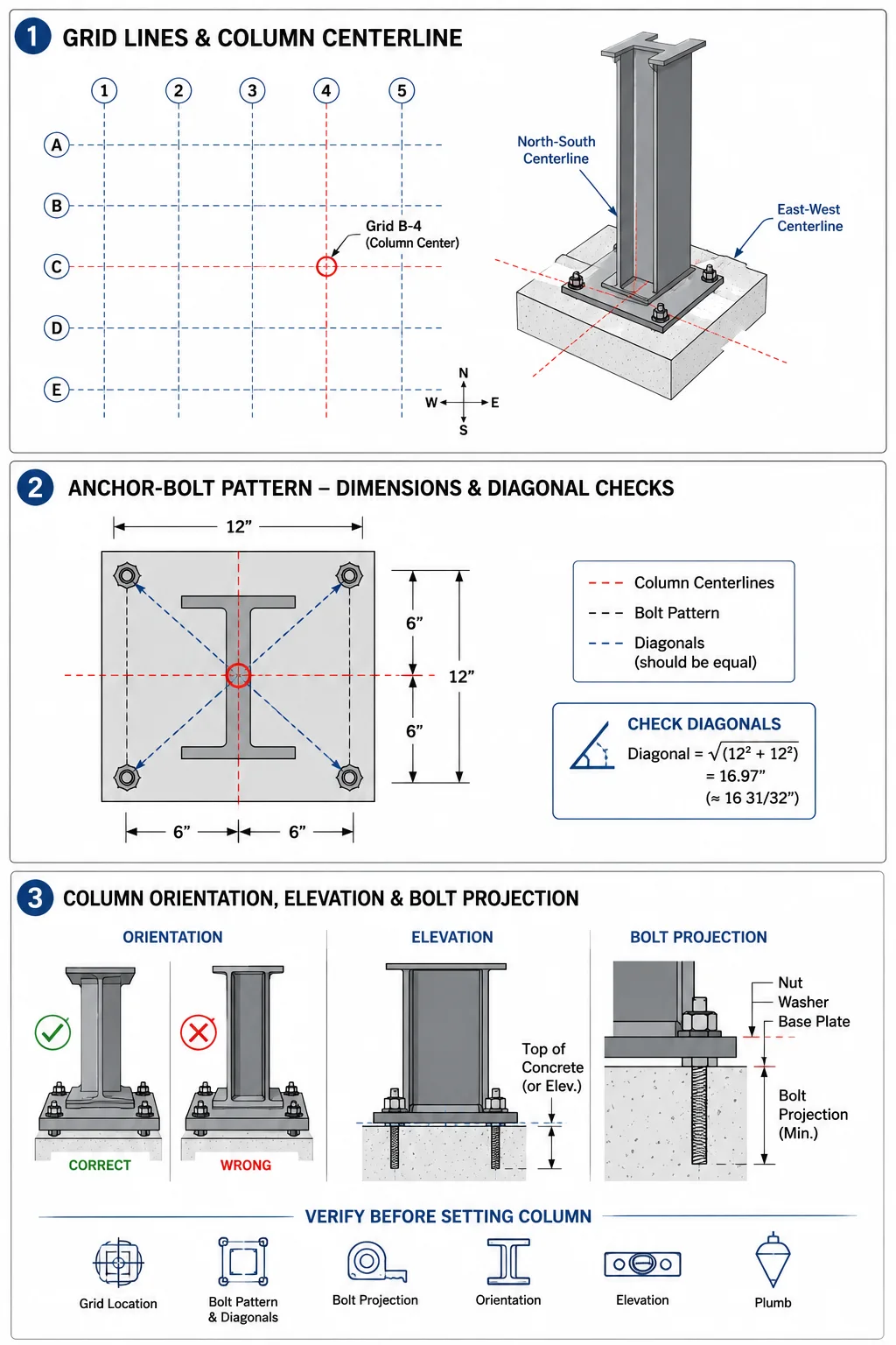
Figure 1. Structural column layout showing grid centerlines, anchor-bolt spacing and diagonals, column orientation, elevation, and bolt projection.
Understand the Base Plate
The base plate is the steel plate attached to the bottom of the column.
Its purpose is to transfer the column load into the foundation while providing the connection between the structural steel and the anchor-bolt system.
A base plate commonly contains:
Anchor-bolt holes
Column centerlines
Column orientation
Plate dimensions
Edge distances
Depending on the design, the column may already be welded to the base plate before erection, or the connection may involve a different engineered arrangement.
Suppose a base plate measures:
18 in. × 18 in.
If the column is centered on the plate, the theoretical center is:
18 ÷ 2 = 9 in.
Therefore, each plate edge would be 9 inches from center.
But again, never assume the column is centered simply because the plate is symmetrical. The fabrication and structural drawings control.
Anchor-Bolt Layout
Anchor bolts hold the structural column/base-plate assembly to the concrete foundation.
A typical four-bolt pattern might look like this:O O + O O
O = anchor bolt
+ = column centerline intersection
The important dimensions normally describe the bolt spacing relative to either the centerline or another bolt.
Suppose the anchor-bolt pattern is:
12 in. × 12 in.
and the pattern is centered on the column.
Half of 12 inches is:
12 ÷ 2 = 6 in.
Each anchor bolt should therefore theoretically be located:
6 inches left/right of center
and
6 inches forward/back of center
This creates the complete 12-inch bolt spacing.
Never Check Only Bolt-to-Bolt
One of the most important field principles is that correct bolt spacing does not necessarily mean the bolt pattern is correctly located.
Imagine four anchor bolts forming a perfect 12 × 12-inch square.
That sounds good.
But the entire square could be shifted 1 inch east.
Bolt-to-bolt measurements would still read perfectly.
The column would still be wrong.
That is why you should verify the bolt pattern against the established column/grid centerlines, not simply against itself.
Check the Anchor-Bolt Pattern Diagonally
Once the horizontal and vertical dimensions are confirmed, check the diagonals.
For a rectangular pattern:
Diagonal = √(Length² + Width²)
For our 12 × 12-inch example:
Diagonal = √(12² + 12²)
Diagonal = √288
Diagonal ≈ 16.97 inches
That is approximately:
16 31/32 inches
Both diagonals should be essentially equal within the applicable project tolerance.
This is the same geometric principle used to square many layouts in construction.
If one diagonal is longer than the other, the pattern is not square.
The 3-4-5 Method
Ironworkers and other construction trades frequently use the 3-4-5 triangle to establish or verify a 90-degree angle.
The relationship comes from:
3² + 4² = 5²
You do not have to use only 3 feet, 4 feet and 5 feet.
You can multiply all three numbers by the same amount.
For example:
6 ft — 8 ft — 10 ft
or:
9 ft — 12 ft — 15 ft
or:
12 ft — 16 ft — 20 ft
The larger the triangle, generally the easier it becomes to detect small layout errors.
This technique is particularly useful when establishing perpendicular reference lines in the field.
Check Anchor-Bolt Projection
Location is only part of the anchor-bolt inspection.
You also need sufficient bolt projection above the finished surface.
The bolt must accommodate the engineered connection arrangement, which may include components such as:
leveling nuts or shims
base plate
washers
top nuts
required thread engagement
The exact assembly depends on the engineered design.
A bolt can be perfectly located horizontally and still cause a serious erection problem if insufficient usable thread remains after the base plate is installed.
Measure projection before the column arrives whenever practical.
Verify Elevation
Horizontal location tells you where the column goes.
Elevation tells you how high it goes.
Structural drawings establish elevations relative to a known benchmark or project datum.
Before erection, the foundation or supporting surface should be checked against the required elevation.
Depending on the engineered connection, columns may be supported temporarily or permanently using leveling nuts, shim packs, setting plates or another specified method before grouting.
The important point is that elevation should be treated as an independent measurement.
You are checking three dimensions:
X — horizontal position
Y — horizontal position
Z — elevation
A column can be correct in X and Y while still being wrong in Z.
Check the Base Plate Before Setting the Column
Before lowering the column onto the anchor bolts, inspect the base plate.
Confirm:
Correct column mark
Correct base-plate configuration
Correct hole pattern
Correct orientation
No damage preventing installation
Anchor bolts correspond with the plate
Structural members are typically identified using piece marks that correspond to erection and fabrication drawings.
Do not rely entirely on appearance.
Two columns can look nearly identical while having different connection details or orientations.
Column Orientation Matters
Getting the column onto the correct anchor bolts is not enough.
The column must also face the correct direction.
A wide-flange column has a web and two flanges.
Connections for beams, braces, platforms and other structural members depend on the designed orientation.
A column rotated 90 degrees may physically fit the same anchor-bolt pattern while putting every connection on the wrong side.
Before signaling the crane to make the final set, verify orientation against the erection drawing.
Setting the Column
As the crane lowers the column, the ironworker guides the base plate toward the anchor bolts.
Hands should never be placed where they can become trapped between the descending steel and the foundation or other fixed objects.
Tag lines, appropriate positioning and established erection procedures are used to control the member.
Once the holes engage the anchor bolts, the column is carefully lowered into position.
Nuts can then be installed according to the erection procedure so the member can be stabilized while alignment and plumbing are checked.
The column should not be treated as permanently complete simply because it is sitting on the bolts.
Check the Column Against the Centerlines
After the column is sitting on the foundation, compare its actual position with the established layout.
Depending on access and the project procedure, measurements may be taken from:
Column flange
Column web
Base-plate edges
Marked centerlines
Survey control
The objective is to determine whether the column centerline matches the required structural location.
If the column width is known, you can sometimes determine its center from the faces.
For example, if a measured column dimension across a particular direction is 10 inches:
10 ÷ 2 = 5 inches
The theoretical center is 5 inches from either corresponding face, assuming the referenced geometry is symmetrical.
Always use the actual structural dimensions and drawing requirements.
Plumbing the Column
After horizontal position and elevation are established, the column must be checked for plumb.
A column can be perfectly centered at the base and still lean several inches at the top.
Traditional and modern methods may include:
Levels
Plumb references
Transit
Theodolite
Total station
The taller the column, the more noticeable a small angular error becomes.
If a column leans only 1/4 inch over 10 feet, extending that same angular error over 40 feet would produce approximately:
1 inch of displacement
That is why structural alignment cannot be judged reliably by eye.
Think in Centerlines, Not Edges
This is one of the most useful habits an ironworker can develop.
Edges can change.
Plate dimensions change.
Column sizes change.
Concrete edges may not be perfectly positioned.
But engineered structural locations are commonly controlled from grid lines and centerlines.
Train yourself to ask:
Where is my control line?
Where is the theoretical center?
What dimension establishes this location?
What drawing controls it?
That mindset prevents many layout mistakes.
Common Layout Mistakes
Many erection problems begin with surprisingly simple errors.
A worker measures from the wrong grid line. A bolt pattern is correctly spaced but shifted from center. The base plate is rotated. A column with a similar piece mark is installed in the wrong location. Bolt projection is not checked. Elevation is assumed from the concrete surface. One diagonal is checked but not the other.
Another dangerous habit is making multiple measurements from previous measurements.
Whenever practical, return to established control.
Control → measurement → verification.
Not:
measurement → measurement → measurement → hope.
A Strong Field Verification Sequence
Before setting structural steel, develop a repeatable process.
First, identify the correct structural grid intersection and confirm any specified offsets. Establish the column centerlines. Check the anchor-bolt locations from those centerlines. Verify bolt-to-bolt spacing. Check both diagonals. Measure bolt projection. Verify elevation. Confirm the column piece mark and base-plate pattern. Verify column orientation.
After the column is set, check its position again and verify plumb before the connection progresses according to the engineered erection procedure.
The principle is simple:
Locate it. Square it. Verify it. Set it. Check it again.
Field Example
Suppose the drawing shows a column centered at:
Grid C-5
The four anchor bolts form a:
14 in. × 18 in. pattern
If the pattern is centered on the column, each bolt should theoretically be:
7 inches from center in one direction
and
9 inches from center in the other direction.
Now calculate the expected diagonal:
Diagonal = √(14² + 18²)
Diagonal = √(196 + 324)
Diagonal = √520
Diagonal ≈ 22.80 inches
You would verify the bolt pattern dimensions and both diagonals, but you would also verify the entire pattern’s relationship to Grid C-5.
That last check is what confirms the bolts are not merely square—they are square in the correct location.
Field Knowledge Check
Before moving on, make sure you can answer these questions:
1. Why isn’t checking bolt-to-bolt spacing enough?
Because an entire correctly spaced bolt pattern can still be shifted away from the required column centerline.
2. What do equal diagonal measurements tell you?
They help verify that a rectangular bolt pattern is square.
3. Why must column orientation be checked?
Because beam, brace and other structural connections depend on the designed orientation of the column.
4. What three basic dimensions control column location?
Horizontal position in two directions and elevation: X, Y and Z.
5. What should ultimately control layout?
The approved project drawings, specifications, established survey/grid control and applicable erection procedures.
The Bigger Lesson
Setting columns may look like crane work from a distance, but successful structural erection depends heavily on layout and verification.
The crane provides the muscle.
The drawings provide the design.
The layout puts the steel where the design says it belongs.
An ironworker who understands grid systems, centerlines, anchor-bolt patterns, diagonals, elevation and column orientation can recognize a problem before thousands of pounds of steel are sitting on top of it.
That is the difference between simply helping set a column and understanding why the column belongs exactly where you’re putting it.


