Næxon Learning Center | Boilermaker Fundamentals
A boiler tube can be installed through a tube sheet without a conventional threaded connection, flange, or external weld being responsible for the primary mechanical fit.
Instead, the tube itself can be mechanically expanded against the wall of the tube-sheet hole.
That process is known as tube rolling, tube expanding, or mechanical tube expansion.
To someone seeing it for the first time, the operation can look simple:
Insert the tube.
Put an expander inside it.
Run the tool.
Pull it out.
Done.
But what is happening between the tube and tube sheet is much more important than the tool movement itself.
The tube’s outside diameter increases.
The tube contacts the tube-sheet hole.
Additional expansion develops the mechanical fit.
The tube and tube sheet respond differently to the force being applied.
And if the boilermaker expands too little—or too much—the joint can fail for completely different reasons.
Understanding that relationship is the foundation of properly rolled boiler tubes.
What Is a Rolled Boiler Tube Joint?
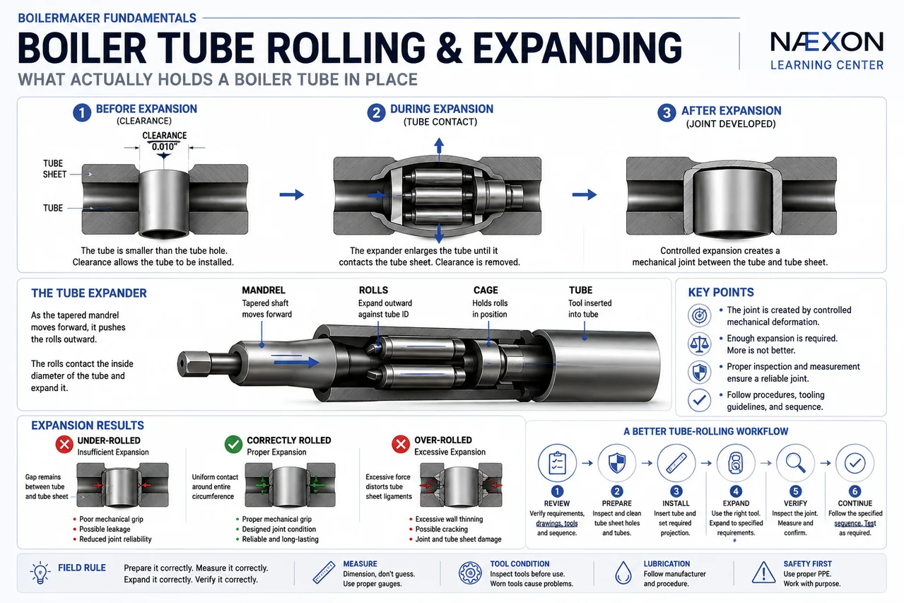
Figure: Boiler tube rolling and expanding—from initial tube-to-tube-sheet clearance through controlled mechanical expansion, showing how the expander creates a secure joint and the difference between under-rolled, correctly rolled, and over-rolled conditions.
A typical tube-and-tube-sheet assembly contains two basic components:
The tube
and
The tube sheet
The tube passes through a precisely prepared hole in the tube sheet.
Before expansion, there is normally clearance between the tube outside diameter and tube-hole inside diameter.
That clearance allows the tube to be installed.
For a simplified example:
Tube OD:
2.000”
Tube-hole ID:
2.010”
Diametral clearance:
0.010”
Initially, the tube can slide into the hole.
The rolling operation changes that.
An expanding tool is inserted into the tube and applies outward radial force from inside the tube.
The tube wall expands until the tube’s outside surface contacts the tube-hole wall.
Continued controlled expansion develops the joint.
The finished connection is therefore produced by controlled mechanical deformation.
The Basic Tube Expander
A mechanical tube expander commonly consists of:
Mandrel
Rolls
Cage
The mandrel is tapered.
As the mandrel advances through the expander, it forces the rolls outward.
The rolls contact the inside diameter of the tube.
As the tool rotates, the rolls travel around the tube’s inside circumference while exerting outward pressure.
The result is controlled enlargement of the tube.
The basic sequence is:
Mandrel advances → rolls move outward → tube expands → tube contacts tube sheet → joint develops
Understanding the mechanical principle is more important than simply knowing how to operate the tool.
What Actually Holds the Tube?
This is the question at the center of the entire process.
The answer is not simply:
“The tube gets bigger.”
There are stages.
Stage 1 — Clearance
Before rolling, the tube is smaller than the tube hole.
There is clearance between them.
The tube is not yet mechanically secured by expansion.
Stage 2 — Tube Contact
As the expander enlarges the tube, the outside diameter increases until it contacts the tube-hole wall.
At this point, the initial clearance has been removed.
But merely touching the tube sheet does not necessarily mean the proper joint has been achieved.
Stage 3 — Controlled Expansion
Additional expansion causes the tube to deform and establishes the required mechanical relationship between the tube and tube sheet.
The exact acceptable expansion depends on the equipment design, materials, tube dimensions, tube-sheet geometry, tooling, applicable procedure, and manufacturer requirements.
The important field lesson is:
The joint depends on controlled expansion—not maximum expansion.
More is not automatically better.
Elastic vs. Plastic Deformation
This is where the physics becomes important.
Materials can deform in two general ways relevant to this operation.
Elastic deformation means the material changes shape under load but tends to return toward its original dimensions when the load is removed.
Plastic deformation means the material has been stressed beyond its elastic range and retains a permanent dimensional change.
During tube expansion, the tube is intentionally enlarged.
The interaction between the tube and surrounding tube sheet creates the mechanical fit.
This is why tube rolling is a controlled deformation process.
The goal is not to destroy either component.
The goal is to produce the required joint without excessive thinning, work hardening, cracking, distortion, or damage.
Why Tube-Hole Preparation Matters
A perfect rolling technique cannot compensate for a badly prepared tube hole.
Before installation, the tube-sheet holes must meet the applicable requirements.
Conditions that can interfere with the joint include:
- burrs
- deep scratches
- corrosion
- dirt
- scale
- oil
- foreign material
- damaged ligaments
- incorrect hole dimensions
- improper surface condition
Imagine trying to establish uniform tube contact against a hole containing a raised burr.
The tube contacts the burr first.
Expansion becomes uneven.
The resulting joint may not behave as intended.
Preparation is part of the installation—not a separate cosmetic step.
This same principle appears throughout industrial work. As covered across the Næxon Learning Center’s pipefitting and welding lessons, good fit-up begins with properly prepared mating surfaces.
Tube Preparation Matters Too
The tube itself also needs inspection.
Before installation, check the tube according to the applicable procedure for conditions such as:
- dents
- out-of-roundness
- damaged ends
- burrs
- contamination
- incorrect dimensions
- surface damage
- corrosion
The tube end may also require preparation depending on the specific joint design.
A damaged tube end can interfere with expander installation and produce inconsistent rolling.
Never assume that because a tube is new, it is automatically ready for installation.
Tube Projection
The distance that the tube extends beyond the face of the tube sheet is commonly called tube projection.
Projection matters.
Too little projection can interfere with the intended finished joint.
Too much projection can also create problems depending on the equipment design and whether additional operations such as flaring or welding are required.
The required projection should come from the approved drawing, procedure, manufacturer requirements, or job specification.
Do not establish projection by eye simply because neighboring tubes “look about right.”
Precision work requires an actual dimension.
Measuring Tube Projection
Suppose the required tube projection is:
3/16”
The boilermaker should establish that projection consistently across the required tubes.
A simple reference gauge may be used where permitted by the procedure.
The important principle is repeatability.
If one tube projects:
3/16”
another:
1/8”
and another:
5/16”
the finished assembly is already inconsistent before rolling begins.
Good tube work starts before the expander ever enters the tube.
Understanding Tube-Wall Reduction
When a tube expands outward, its wall thickness changes.
The tube material does not simply appear from nowhere.
As the tube diameter increases, the wall can become thinner.
This is why excessive rolling is dangerous.
A simplified starting tube might have:
Outside diameter:
2.000”
Wall thickness:
0.120”
As the tube is expanded, the OD increases and the wall experiences deformation.
The acceptable amount of expansion or wall reduction is not something to guess.
It depends on the joint design and applicable procedure.
The field lesson is simple:
Enough expansion is necessary. Excessive expansion is damage.
Under-Rolling
Under-rolling occurs when the tube has not been expanded sufficiently to establish the required joint.
Possible consequences can include:
- leakage
- insufficient mechanical grip
- tube movement
- poor sealing
- premature joint problems
A tube may appear installed but still lack the required expansion.
Visual appearance alone cannot always verify the joint.
That is why controlled tooling, measurements, procedures, and inspection matter.
Over-Rolling
A common beginner assumption is:
If tight is good, tighter must be better.
Tube rolling does not work that way.
Excessive expansion can contribute to:
- excessive tube-wall thinning
- work hardening
- cracking
- tube damage
- tube-sheet distortion
- ligament damage
- difficult future repairs
- reduced joint reliability
The boilermaker isn’t trying to make the tube as tight as physically possible.
The objective is to achieve the specified joint condition.
Stop when the required expansion has been achieved.
What Is a Tube-Sheet Ligament?
Look at a tube sheet containing hundreds of holes.
The steel remaining between adjacent tube holes is called the ligament.
For example:
○ ○ ○
○ ○ ○
○ ○ ○
The material between those circles is structurally important.
If excessive expansion distorts the area surrounding one hole, it can influence the material between neighboring holes.
This becomes especially important when working with closely spaced tube patterns.
A tube joint therefore cannot always be viewed as an isolated hole.
The entire tube sheet is a connected structure.
Why Rolling Sequence Can Matter
On certain jobs, the order in which tubes are expanded may be controlled.
Why?
Because every expanded tube introduces force into the tube sheet.
With many tubes installed in a confined pattern, expansion can create cumulative effects.
The required rolling sequence depends on the equipment and approved procedure.
The lesson for the field is:
Don’t invent your own sequence when the job specifies one.
The sequence may have been selected specifically to control distortion and maintain dimensional stability.
Straight vs. Angular Tube Entry
The expander should operate in the intended alignment with the tube.
If the tool is forced into the tube at an angle, the rolls may not load the tube wall uniformly.
That can contribute to:
- uneven expansion
- scoring
- damaged tube ID
- inconsistent wall reduction
- tool wear
- poor joint quality
Good tooling technique means keeping the expander properly aligned and allowing it to perform the operation it was designed to perform.
Lubrication and Tool Condition
Tube expanders are precision mechanical tools.
The rolls and mandrel operate under significant contact pressure.
Tool condition directly affects the quality of the expansion.
Inspect for:
- worn rolls
- damaged mandrels
- debris
- metal pickup
- damaged cages
- improper movement
- incorrect tool size
Lubrication requirements should follow the tool manufacturer and job procedure.
Too little lubrication can increase friction and tool wear.
Improper lubrication or contamination can create other problems.
Precision tooling should be treated like precision tooling.
One Expander Does Not Fit Everything
Tube expanders are selected for specific applications.
Important variables can include:
Tube inside diameter
Tube wall thickness
Tube-sheet thickness
Required rolling length
Tube material
Joint configuration
Tube-hole geometry
Using the wrong expander can produce an incorrect rolling length or improper contact.
Before beginning the job, verify that the tooling actually matches the tube and tube sheet being worked on.
Rolling Length
The expander must work over the correct portion of the tube within the tube sheet.
If the rolling zone is too short, the required joint may not be developed.
If it extends into an unintended area, damage can occur.
This becomes especially important near the back face of the tube sheet.
The operator needs to know:
Where should the expansion start?
Where should it stop?
How thick is the tube sheet?
What is the effective rolling length?
Tool setup should answer those questions before production work begins.
A Simplified Field Example
Suppose a boiler repair involves:
Tube OD:
2.000”
Tube wall:
0.120”
Tube-sheet thickness:
1.500”
Required projection:
3/16”
The boilermaker should not begin by simply inserting an expander and running it.
A better process is:
Verify tube identification.
Inspect the tube.
Inspect the tube hole.
Confirm the required projection.
Confirm expander size.
Confirm rolling length.
Confirm tool setup.
Install the tube.
Establish projection.
Perform the expansion according to the approved procedure.
Inspect the completed joint.
Record or verify required measurements.
Then proceed according to the job’s quality-control requirements.
The actual rolling operation may take seconds.
The preparation is what makes those seconds successful.
Mechanical Rolling vs. Seal Welding
Some tube-to-tube-sheet joints may incorporate welding in addition to mechanical expansion.
It is important to understand that these are related but distinct operations.
A mechanically expanded joint develops its fit through controlled tube expansion.
A welded tube-to-tube-sheet joint uses a specified weld configuration.
Some designs use combinations of mechanical expansion and welding.
The exact sequence and purpose depend on the equipment design and procedure.
Do not assume that adding a weld automatically fixes an improperly expanded joint—or that a rolled joint automatically requires welding.
Follow the engineered joint design.
For readers building their welding fundamentals, the Næxon Learning Center’s welding lessons explain why joint preparation, heat input, fit-up, and procedure control are equally important when welding becomes part of the assembly.
Why Cleanliness Becomes Even More Important Before Welding
If the tube-to-tube-sheet joint will also be welded, contamination becomes especially important.
Oil or other material introduced during tube preparation or expansion can interfere with subsequent welding if it is not properly controlled.
The required cleaning process should therefore be coordinated with the complete joint procedure.
Think beyond the operation you’re performing right now.
A professional tradesman understands what operation comes next.
Tube Rolling Is a Measurement Job
Experienced boilermakers develop a feel for their tools.
That experience matters.
But “feel” should not replace the required measurements.
Tube rolling involves measurable variables:
- tube OD
- tube ID
- wall thickness
- tube-hole diameter
- tube-sheet thickness
- projection
- rolling length
- expansion
- wall reduction
When those dimensions matter to the specification, measure them.
The same principle applies to flange alignment, pipe fabrication, shaft alignment, structural layout, and virtually every other precision industrial trade covered throughout the Næxon Learning Center.
Experience tells you what to look for.
Measurement tells you what is actually there.
Troubleshooting a Leaking Rolled Tube
Suppose a tube leaks during testing.
The wrong response is immediately assuming:
“Roll it harder.”
First determine why the joint leaked.
Possible causes can include:
- insufficient expansion
- tube-hole damage
- tube damage
- contamination
- improper tooling
- incorrect rolling length
- incorrect tube projection
- crack or defect
- excessive previous expansion
- tube-sheet condition
If a tube has already been over-expanded, additional rolling may make the problem worse.
Troubleshooting should identify the cause before applying the correction.
A Better Tube-Rolling Workflow
1. Review the requirements
Verify tube material, dimensions, projection, expansion requirements, tooling, sequence, and inspection criteria.
2. Inspect the tube sheet
Check the tube holes and surrounding ligaments.
3. Inspect the tube
Verify dimensions and condition.
4. Prepare mating surfaces
Clean and prepare according to the approved procedure.
5. Install the tube
Position it without damaging the tube end or hole.
6. Set projection
Establish the required dimension accurately.
7. Verify the expander
Confirm size, rolling length, condition, and setup.
8. Expand the tube
Perform the rolling operation using the approved technique.
9. Inspect the joint
Look for damage, irregularities, improper projection, or other unacceptable conditions.
10. Verify required measurements
Confirm the joint meets the specified acceptance criteria.
11. Continue the specified sequence
Do not randomly move around the tube sheet if a rolling sequence has been established.
12. Perform final inspection and testing
The joint isn’t proven simply because the expander was removed successfully.
Common Tube-Rolling Mistakes
One of the biggest mistakes is over-rolling because the operator wants to “make sure it’s tight.”
Another is failing to properly prepare the tube hole.
Another is using worn or incorrect tooling.
Another is inconsistent tube projection.
Another is ignoring the specified rolling length.
Another is treating every leaking tube as an under-rolled tube.
And another is relying entirely on feel instead of verifying the required measurements.
Most of these mistakes have the same root cause:
The operation is being treated as brute-force work instead of precision mechanical work.
Field Rule: More Expansion Is Not More Quality
Remember this:
Under-expanded = potentially inadequate joint
Correctly expanded = intended joint
Over-expanded = potentially damaged joint
The objective is the middle condition.
Tube rolling is controlled deformation.
Once you understand that, the entire process makes more sense.
Knowledge Check
A boilermaker finishes expanding a tube and decides to give the expander several additional passes “just to make sure it’s tight.”
Is that automatically good practice?
No.
Once the required expansion has been achieved, unnecessary additional expansion can increase tube-wall reduction, work hardening, distortion, and the possibility of damage.
The objective is not maximum tightness.
The objective is the specified expansion.
Practical Exercise
You are preparing to roll a replacement boiler tube.
Given:
Tube OD: 2.000”
Tube wall: 0.120”
Tube-hole ID before installation: 2.010”
Required projection: 3/16”
Before touching the expander, identify what should be verified.
At minimum, think through:
Tube condition.
Tube-hole condition.
Clearance.
Tube-sheet thickness.
Required rolling length.
Tube projection.
Expander size.
Expander condition.
Tool setup.
Specified expansion criteria.
Required rolling sequence.
Inspection requirements.
Now imagine you discover a deep burr inside the tube hole.
Do you install the tube and compensate by rolling harder?
No.
Correct the tube-hole condition according to the approved procedure before attempting to establish the joint.
That is the central lesson:
Preparation → Measurement → Controlled Expansion → Verification
Not:
Insert → Roll Hard → Hope.
The Boilermaker Standard
A boiler may contain hundreds or thousands of tubes.
Each one looks like a small component.
But every tube joint is part of the pressure-containing and heat-transfer system that allows the equipment to operate.
A skilled boilermaker understands that tube rolling is not simply forcing metal outward.
It is a controlled relationship between:
Tube
Tube hole
Tube sheet
Tooling
Material deformation
Measurement
Procedure
Get those relationships right and the expander becomes a precision installation tool.
Ignore them and the same tool can damage the very joint you’re trying to create.
The field rule is simple:
Prepare it correctly.
Measure it correctly.
Expand it correctly.
Verify it correctly.
That precision-first approach is the same standard carried throughout the Næxon Learning Center, from boilermaker fundamentals and welding to pipefitting, millwright work, rigging, electrical, and instrumentation.


