Næxon Learning Center | Industrial Carpenter Fundamentals
Getting a layout square sounds simple when you have an open slab and can measure diagonally from corner to corner. Industrial construction rarely gives you that luxury. Existing equipment, pipe racks, foundations, structural steel, excavations, temporary barricades, or other trades may block the diagonal you normally want to measure.
That does not mean you have to guess.
A carpenter can establish an accurate 90° corner without measuring the full diagonal by working from control lines, known reference points, and basic geometry. One of the most useful methods is the 3-4-5 method.
Understanding What “Square” Actually Means
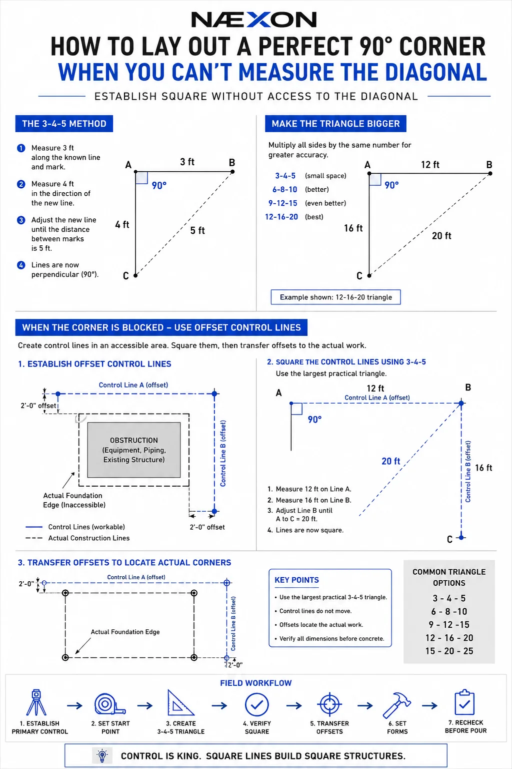
Two lines are square when they intersect at exactly 90 degrees.
If one line is already established from the drawing, you do not necessarily need access to the opposite corner of the structure. You only need enough clear space along the two directions to prove that the angle between them is 90 degrees.
That is where the 3-4-5 method becomes extremely useful.
The method comes from the Pythagorean theorem:
A² + B² = C²
For a 3-4-5 triangle:
3² + 4² = 5²
9 + 16 = 25
Because those dimensions form a perfect right triangle, the angle between the 3 side and the 4 side is exactly 90 degrees.
The 3-4-5 Method
Suppose you need to establish a perpendicular line from an existing control line.
Start at the point where the new 90° line needs to begin.
Measure 3 feet along the established control line and mark that point.
From the starting point, measure approximately 4 feet in the direction you believe the perpendicular line should run.
Now measure between the 3-foot mark and the 4-foot mark.
Adjust the second line until that diagonal measurement is exactly:
5 feet
Once you have:
3 ft × 4 ft × 5 ft
you have established a 90° corner.
But on industrial layouts, using only three and four feet may not provide enough accuracy.
Make the Triangle Bigger
One of the easiest ways to improve field accuracy is to multiply all three dimensions by the same number.
Instead of:
3 – 4 – 5
Use:
6 – 8 – 10
Or:
9 – 12 – 15
Or:
12 – 16 – 20
The geometry remains exactly the same.
Whenever space allows, a larger triangle is usually easier to lay out accurately because a small angular error becomes easier to detect over a longer distance.
For example, suppose you are establishing the corner of a large equipment foundation.
You could measure:
12 ft along Line A
16 ft along Line B
Then adjust Line B until the distance between those two marks is exactly:
20 ft
Line A and Line B are now perpendicular.
What If the Corner Is Blocked?
This is where industrial layout becomes more interesting.
Imagine the actual corner of the foundation is underneath existing piping or behind operating equipment. You cannot physically stand at the corner and pull your measurements from it.
Instead of abandoning the layout, establish offset control lines.
An offset control line is simply a known line located a specific distance away from the actual construction line.
For example, the drawing may establish a foundation edge, but that edge is inaccessible.
You establish another line exactly:
2’-0” away
and parallel to the foundation edge.
That becomes your working control line.
You can then establish a perpendicular offset line using the 3-4-5 method.
Once both control lines are square, transfer the required offsets back to locate the actual foundation corners.
The obstruction never needs to be part of your measurement.
Control Lines Are More Important Than Form Boards
A common mistake is trying to square the form itself before establishing reliable control.
The better sequence is:
Control → Layout → Forms → Verification
Establish your primary control line first.
Then establish the perpendicular control line.
Verify the 90° relationship.
Locate the actual concrete dimensions from those lines.
Only then should the formwork be positioned.
Forms can move.
Control points should not.
That is why experienced layout crews protect their control points throughout the job.
Extended Reference Points
Sometimes there is not enough room near the actual work area to create a useful 3-4-5 triangle.
You can extend the layout beyond the structure.
Imagine a foundation corner surrounded by congestion.
Instead of trying to make a tiny triangle beside the form, extend the two control lines into an open area.
Create your larger 3-4-5 triangle there.
Once the lines are proven perpendicular, extend those same lines back toward the foundation using string lines, a laser, chalk lines, or appropriate surveying equipment.
The 90° relationship remains the same regardless of where along those lines you verify it.
Example: Equipment Foundation With an Obstruction
Suppose the drawing calls for an equipment foundation measuring:
10’-0” × 16’-0”
An existing pipe rack prevents you from measuring diagonally across the foundation.
Start by establishing the 16-foot longitudinal control line from known project control.
Choose the point where the perpendicular line must originate.
Measure:
12 feet along the longitudinal control line.
Establish your approximate perpendicular line and measure:
16 feet along it.
Now measure between those two marks.
Adjust the perpendicular line until the measurement becomes:
20 feet exactly.
You have now established a true 90° relationship without ever measuring across the actual foundation.
From those control lines, locate the four finished concrete corners.
Then position the formwork around those points.
Never Trust Only One Check
After establishing square, verify the layout independently whenever possible.
Check the dimensions shown on the drawing.
Check offsets from project control.
Check centerlines.
Check the relationship to nearby foundations or equipment.
And once the obstruction is no longer an issue, check the finished diagonals if they become accessible.
A correct 3-4-5 triangle proves the two lines are perpendicular. It does not automatically prove that the entire structure is located in the correct place.
A perfectly square foundation can still be perfectly square in the wrong location.
Common Field Mistakes
One mistake is measuring from the edge of a form board instead of a known control line. Another is using different reference faces when taking measurements.
A carpenter may also create an accurate 3-4-5 triangle but accidentally move the starting point afterward.
Another common problem is using a triangle that is unnecessarily small. A tiny measurement error on a 3-foot leg can create considerably more error when the line is extended 40 or 50 feet.
And never assume an existing wall, slab edge, column, curb, or piece of equipment is square simply because it looks straight.
Tie the layout back to established project control whenever possible.
Field Workflow
Establish the primary control line from the drawing or survey control. Mark the required intersection point. Extend the second line approximately perpendicular to the first. Create the largest practical 3-4-5 triangle. Adjust the second line until the diagonal measurement is correct. Extend both control lines beyond the work area when possible. Transfer the required offsets to establish the actual construction lines. Set the formwork. Recheck dimensions and control before concrete placement.
Field Rule
DON’T SQUARE THE FORM FIRST. SQUARE THE CONTROL LINES FIRST.
Once your control is correct, everything else can be built from it.
Knowledge Check
1. Why does a 3-4-5 triangle create a 90° angle?
Because 3² + 4² = 5², satisfying the Pythagorean theorem for a right triangle.
2. Is 6-8-10 also a valid layout triangle?
Yes. It is simply the 3-4-5 triangle multiplied by two.
3. Why use a larger triangle when possible?
It makes small angular errors easier to detect and improves layout accuracy over longer distances.
4. What should you do when the actual corner is inaccessible?
Establish offset control lines in an accessible area, square those lines, and transfer the dimensions back to the actual work.
5. Does a correct 3-4-5 measurement prove the foundation is in the correct location?
No. It proves the two measured lines are perpendicular. The layout must still be tied to project control.
Practical Exercise
You need to establish a perpendicular control line, but equipment blocks the actual corner.
You have enough open space to measure 15 feet along the first control line.
Using the 3-4-5 relationship multiplied by five, determine the other two measurements.
Answer:
3 × 5 = 15 ft
4 × 5 = 20 ft
5 × 5 = 25 ft
Measure 15 feet along the established line and 20 feet along the proposed perpendicular line. Adjust the second line until the distance between those two marks is exactly 25 feet.
You now have a 90° control line that can be extended back toward the work.
Næxon Learning Center — Learn the trade. Understand the work. Build it right.


