Learn | Pipefitting • Layout & Math • Intermediate
A 45-degree equal spread offset is a common pipefitting layout used when multiple parallel pipes need to offset around an obstruction while maintaining the same spacing from one another. The math for a single 45° offset is straightforward. The challenge begins when several pipes are running side by side and every line needs to stay evenly spaced through the offset.
The key is understanding that equal spread is based on maintaining the same perpendicular centerline spacing between the pipes—not simply measuring the original spacing straight across the offset.
What Is an Equal Spread Offset?
Imagine three parallel pipes running 6 inches apart center-to-center. All three pipes need to make the same 45° offset.
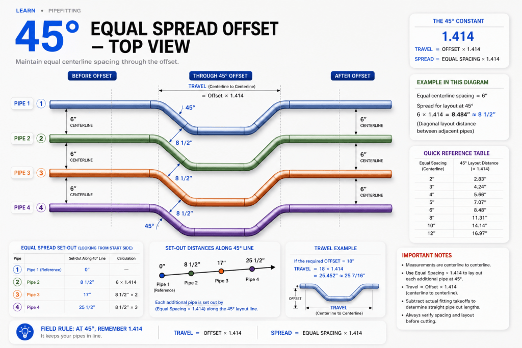
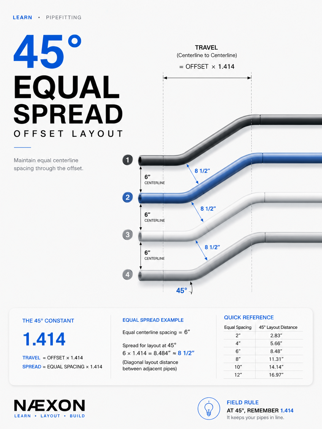
45° equal spread offset layout showing how parallel pipes maintain consistent centerline spacing through the offset. At 45°, multiply the equal spacing by 1.414 to determine the layout distance between each pipe.
Before the offset:
Pipe 1 → 6” → Pipe 2 → 6” → Pipe 3
After the offset, you still want the pipes to remain:
Pipe 1 → 6” → Pipe 2 → 6” → Pipe 3
That means the fittings cannot simply be lined up directly beside each other. Their locations must be staggered to compensate for the 45° angle.
The 45° Constant
For a standard 45° offset, one of the most important numbers to remember is:
1.414
This is the 45° travel multiplier.
Travel = Offset × 1.414
Example:
If the required offset is 12”:
12 × 1.414 = 16.968”
Approximately:
16 31/32” travel
This tells you the theoretical centerline travel between the two 45° turns.
Equal Spread Uses the Same 1.414 Relationship
Suppose two pipes must remain 6” center-to-center.
To determine the layout distance associated with that spacing at 45°:
6 × 1.414 = 8.484”
Approximately:
8 1/2”
So a 6” equal spread produces approximately 8 1/2” of diagonal layout distance at 45°.
Quick Reference
Equal Pipe Spacing
45° Layout Distance
2”
2.83”
3”
4.24”
4”
5.66”
5”
7.07”
6”
8.48”
8”
11.31”
10”
14.14”
12”
16.97”
The basic formula is:
Equal Spread × 1.414 = 45° Layout Distance
Field Example: Three Parallel Pipes
Assume you have three pipes running parallel at:
6” center-to-center
You need all three pipes to make the same 45° offset while keeping that 6” spacing.
First calculate the spread layout:
6 × 1.414 = 8.484”
Round appropriately for the accuracy required on the job:
≈ 8 1/2”
Your corresponding layout points are therefore staggered by approximately 8 1/2”:
Pipe 1: Reference point
Pipe 2: 8 1/2” from Pipe 1’s reference
Pipe 3: another 8 1/2” from Pipe 2’s reference
From Pipe 1 to Pipe 3:
8.484 × 2 = 16.968”
Approximately:
16 31/32”
This staggering allows the pipes to maintain their equal centerline spacing through the 45° section.
Step-by-Step Field Layout
Step 1 — Establish your pipe centerlines.
Confirm the actual center-to-center spacing of the parallel pipes. Do not assume the spacing from pipe edges unless the layout specifically calls for edge-to-edge dimensions.
Step 2 — Establish your first reference point.
Choose one pipe as the starting reference. This is usually the outside pipe or whichever line has the controlling dimension on the drawing.
Step 3 — Determine the equal spread.
Measure the perpendicular centerline distance between adjacent pipes.
Example:
Spread = 6”
Step 4 — Multiply by 1.414.
6 × 1.414 = 8.484”
This gives the 45° layout relationship for the next pipe.
Step 5 — Lay out each additional pipe.
Move approximately 8 1/2” for each successive pipe when the spacing is 6”.
Step 6 — Lay out the actual offset.
Now calculate the required travel for the offset itself:
Offset × 1.414 = Travel
If the offset is 18”:
18 × 1.414 = 25.452”
Approximately:
25 7/16”
Step 7 — Account for fitting takeoff.
The calculated travel is centerline geometry. Your actual straight-pipe cut length depends on the fittings being used.
Do not automatically cut the pipe at the calculated travel dimension.
For a fabricated spool:
Centerline travel − fitting takeoffs = straight pipe cut length
Always use the actual fitting dimensions required by the job.
Why Pipefitters Get This Wrong
One common mistake is keeping all of the first 45s directly in line with one another.
That may look correct before fabrication, but the pipe spacing changes once the lines travel through the angled section.
Another mistake is using the normal pipe spacing as the measurement along the 45° line.
For example, if the pipes are 6” apart, a fitter may incorrectly lay out another fitting exactly 6” away along the diagonal.
At 45°, that does not represent 6” of perpendicular separation.
The diagonal relationship is approximately:
6 × 1.414 = 8.484”
Geometry controls the layout.
Centerline-to-Centerline Matters
Whenever possible, perform equal-spread calculations using pipe centerlines.
This becomes especially important when dealing with different pipe sizes.
For equal-size pipes, maintaining equal centerline spacing is simple.
For different-size pipes, first determine what the drawing actually requires:
Equal centerline spacing?
Equal clear spacing between pipe ODs?
Those are not the same thing.
If a rack requires equal clearance between different pipe sizes, convert the required clearance into centerline spacing before performing the 45° layout.
For two different pipe ODs:
Centerline spacing = ½ OD₁ + Clearance + ½ OD₂
Then apply the appropriate 45° geometry.
Field Rule
At 45°, remember 1.414.
It appears repeatedly in pipefitting layout because a 45° triangle has equal legs.
For a basic 45° offset:
Offset × 1.414 = Travel
For equal-spread geometry:
Spread × 1.414 = Diagonal layout distance
Understanding why the number works is better than simply memorizing it. Once you recognize the 45° right triangle in the layout, the calculation becomes much easier to visualize.
Before You Cut
Check the layout from both directions.
Verify:
Centerline spacing → offset → travel → fitting takeoff → cut length
Then physically visualize where every pipe will land.
A few minutes checking the geometry on the floor or fabrication table can prevent an entire group of pipes from being fabricated with the wrong spread.
Knowledge Check
- What multiplier is commonly used for a 45° offset?
- If an offset is 10”, what is the theoretical travel?
- If parallel pipes have a 5” equal spread, what is the corresponding 45° layout distance?
- Why should equal-spread calculations normally be made from pipe centerlines?
- Why can’t fitting takeoff simply be ignored when determining the final cut length?
Answers
- 1.414
- 10 × 1.414 = 14.14”
- 5 × 1.414 = 7.07”
- Because the geometry of the piping system is established from the pipe centerlines.
- Because calculated travel represents centerline geometry; the fittings occupy part of that distance.
Practical Exercise
Lay out four parallel pipes spaced 8” center-to-center that must make the same 45° offset.
First calculate the equal-spread layout:
8 × 1.414 = 11.312”
Approximately:
11 5/16”
Starting with Pipe 1 as your reference:
Pipe 1: 0
Pipe 2: 11 5/16”
Pipe 3: 22 5/8”
Pipe 4: 33 15/16” approximately
Now calculate the travel for whatever offset is required, account for the actual fitting takeoffs, and verify the final centerline spacing before fabrication.
Master this layout and a rack of parallel offsets becomes much easier to plan. The goal isn’t just to make one pipe fit. The goal is to make the entire group travel together, maintain its spacing, and land where the drawing says it should.


