
A flare is one of the most visible safety systems in a refinery. The tall stack and flame can be seen from miles away, especially during startups, shutdowns, process upsets, emergency depressurization, and other abnormal operating conditions.
But a refinery flare is much more than a pipe with a flame at the top.
The complete flare system is an engineered pressure-relief and disposal network designed to collect combustible gases and vapors from process equipment, separate liquids from the gas stream, control the movement of gases through the system, and safely burn combustible material at a designated location away from operating equipment and personnel.
For refinery workers and industrial tradespeople, understanding the flare system is important because it connects directly with pressure vessels, distillation columns, reactors, compressors, relief valves, knockout drums, headers, pumps, instrumentation, ignition systems, and many other pieces of refinery equipment.
What Is a Refinery Flare System?
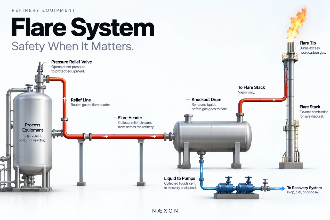
Figure 1. Refinery Flare System. Simplified diagram showing how excess hydrocarbon gas travels from process equipment through the relief system and flare header, passes through the knockout drum for liquid removal, and continues to the flare stack for controlled combustion.
A refinery flare system is a controlled disposal system for combustible gases and vapors that cannot safely remain inside process equipment.
When pressure inside equipment approaches an unsafe condition, a pressure-relief device may open and route material into the flare system.
The basic path is:
Process Equipment → Pressure Relief Device → Flare Header → Knockout Drum → Flare Stack → Flare Tip → Controlled Combustion
Instead of allowing hydrocarbons to discharge directly around process equipment, the flare system transports them to a designated location where combustible gases can be burned.
This makes the flare system one of the refinery’s most important layers of pressure protection.
Why Refineries Need Flare Systems
Refinery equipment operates under combinations of pressure, temperature, flow, chemical reaction, and heat transfer.
Abnormal conditions can cause pressure to increase rapidly.
Possible causes include:
- Blocked process outlets.
- Loss of cooling.
- Loss of electrical power.
- Compressor trips.
- Control-valve failures.
- Equipment fires.
- Process instability.
- Startup conditions.
- Shutdown conditions.
- Emergency depressurization.
- Unexpected vapor generation.
- Loss of utilities.
Pressure vessels, columns, reactors, exchangers, and piping systems cannot simply be allowed to continue building pressure indefinitely.
Pressure-relief systems provide a controlled escape path.
The flare system provides a destination for many of those relief streams.
This connects directly with the refinery pressure vessels and separators covered elsewhere in the Næxon Learning Center, because pressure protection must be considered as part of the entire equipment system rather than as an isolated device.
The Flare Is Part of a Much Larger System
When most people look at a refinery flare, they notice the stack and flame.
Most of the flare system, however, exists long before the gas reaches the stack.
A simplified refinery flare network looks like:
Process Units → Relief Valves → Relief Branch Lines → Flare Header → Knockout Drum → Flare Stack → Flare Tip
Multiple process units may connect to the same flare network.
That means the flare system can potentially receive gases and vapors from many different pieces of equipment throughout the refinery.
The visible flame is only the final destination.
Pressure-Relief Devices
Pressure-relief valves are among the most important devices connected to the flare system.
A relief valve is designed to open when process pressure reaches a predetermined condition.
A simplified sequence is:
Pressure Rises → Relief Valve Opens → Material Enters Relief Piping → Flare Header
Once the abnormal condition is corrected and pressure decreases sufficiently, the relief valve can close according to its design and operating conditions.
The relief valve protects the process equipment from overpressure, but the valve is only one part of the protection system.
The downstream relief piping and flare network must also safely handle the material released through that valve.
The Flare Header
The flare header is the large piping network that collects relief streams from throughout the refinery.
Individual relief lines from equipment connect into larger branch headers, which eventually connect to a main flare header.
The basic arrangement is:
Individual Relief Lines → Branch Headers → Main Flare Header → Knockout Drum → Flare
During a significant refinery upset, multiple relief devices may discharge into the system at the same time.
The flare header must therefore be engineered to handle expected flow, pressure drop, backpressure, temperature changes, liquid accumulation, thermal expansion, dynamic loading, and other operating conditions.
Why Flare Piping Is Different
Flare piping can behave very differently from normal process piping.
During ordinary refinery operation, some portions of the flare system may experience relatively little flow.
During a major process upset, extremely large quantities of vapor can suddenly enter the flare network.
That can create rapid changes in:
- Flow rate.
- Pressure.
- Temperature.
- Pipe movement.
- Mechanical loading.
- Noise.
- Vibration.
- Thermal expansion.
This is why flare-piping layout, supports, slope, branch connections, expansion allowances, and drainage arrangements are extremely important.
Flare Header Slope
Flare headers are commonly arranged so liquids can drain toward designated collection points instead of remaining trapped inside the piping.
This matters because hydrocarbons and water can condense or accumulate inside the flare system.
Liquid accumulation can create serious operating problems.
Possible causes of poor drainage include:
- Incorrect piping slope.
- Damaged pipe supports.
- Settlement.
- Unintended low points.
- Improper field modifications.
- Plugged drains.
- Pipe deformation.
For pipefitters, flare-header slope should never be treated casually.
A small elevation mistake on large-bore flare piping can create an unintended liquid pocket that remains in the system for years.
The Flare Knockout Drum
Before flare gas reaches the stack, it commonly passes through a flare knockout drum.
The knockout drum is one of the most important pieces of equipment in the entire flare system.
Its job is to separate entrained liquid from the vapor stream and collect liquid entering or forming within the flare network.
The process is:
Gas + Entrained Liquid → Knockout Drum → Liquid Separates → Gas Continues Toward Flare
Inside the drum, gas velocity decreases and liquid droplets have an opportunity to separate from the vapor.
The vapor continues toward the flare stack.
The separated liquid remains in the drum until it can be removed through the appropriate recovery or disposal system.
Why Liquids Must Be Removed
The flare is primarily intended to burn gases and vapors.
Large quantities of liquid reaching the flare tip can create dangerous conditions.
Potential consequences include:
- Burning liquid droplets.
- Excessive smoke.
- Unstable combustion.
- Hydrocarbon carryover.
- Increased radiant heat.
- Mechanical problems.
- Fire hazards around the flare area.
The knockout drum therefore acts as an important protective barrier between the flare header and the flare stack.
Knockout Drum Liquid Removal
Liquid collected in the knockout drum must eventually be removed.
Depending on refinery design, pumps or another engineered arrangement may transfer the collected liquid to a slop, recovery, or disposal system.
The simplified arrangement is:
Flare Header → Knockout Drum
Vapor → Flare Stack
Liquid → Knockout Drum Pumps → Recovery System
Level instrumentation is extremely important.
If the liquid level becomes too high, the drum can lose some of its ability to handle additional liquid during a major relief event.
Flare Stack
The flare stack elevates combustion above the surrounding refinery.
Its height helps keep the flame, radiant heat, and combustion products away from personnel and nearby process equipment.
The stack must support:
- Flare tip.
- Pilot equipment.
- Ignition equipment.
- Associated piping.
- Structural loads.
- Wind loads.
- Thermal effects.
Some flare stacks are self-supported.
Others may use guy wires or other structural arrangements.
The exact design depends on the facility and flare system.
Flare Tip
The flare tip is located at the top of the stack.
This is where flare gas exits and burns.
The tip is designed to promote stable combustion under the operating conditions anticipated for that system.
Flare tips operate in an extremely demanding environment.
They are exposed to:
- High temperature.
- Repeated thermal cycling.
- Combustion.
- Weather.
- Wind.
- Corrosion.
- Vibration.
Flare-tip condition is therefore an important part of flare-system reliability.
Pilot Flame
A refinery flare normally uses pilot flames or another engineered ignition arrangement to provide reliable ignition at the flare tip.
The pilot acts as the ignition source.
When combustible flare gas reaches the tip, the pilot helps ensure that the gas ignites rather than being released unburned.
Pilot reliability is therefore extremely important.
Flare Ignition System
Flare systems can incorporate dedicated pilot ignition and monitoring equipment.
Operators need confidence that the required ignition source is available.
Depending on the design, instrumentation may monitor pilot status and alert operators when a pilot is lost.
Ignition systems vary between refineries, but the objective remains the same:
Provide reliable ignition whenever combustible flare gas reaches the flare tip.
Purge Gas
Flare systems may use purge gas to help prevent air from traveling backward into the flare system.
Air entering a hydrocarbon-containing flare network could create a combustible mixture inside the piping.
Maintaining the proper internal atmosphere is therefore important.
Purge gas provides a small continuous flow through portions of the flare system.
The specific purge arrangement depends on the flare design.
Molecular and Velocity Seals
Some flare systems incorporate specialized devices near the upper portion of the flare stack to help reduce air infiltration and lower purge-gas requirements.
Depending on design, these may include molecular, buoyancy, or velocity-type seals.
Their purpose supports one fundamental objective:
Help keep air from entering the flare system and creating an unsafe mixture.
Steam-Assisted Flares
Some refinery flares use steam near the flare tip.
Steam can improve mixing between hydrocarbon gas and surrounding air.
Improved mixing can help reduce visible soot under appropriate operating conditions.
The relationship is generally:
Better Mixing → Better Combustion → Less Soot
However, flare assistance must be properly controlled.
Too little assistance may allow smoky combustion.
Too much assistance can also negatively affect flare performance.
Why Some Flares Smoke
Black smoke from a refinery flare is generally associated with soot formation.
Heavy hydrocarbons can require effective mixing with air for cleaner combustion.
When the mixture does not receive enough oxygen or adequate mixing, soot formation can increase.
Possible factors include:
- Hydrocarbon composition.
- High flare loading.
- Insufficient air mixing.
- Insufficient steam or air assistance where applicable.
- Rapid process changes.
A large or smoky flare does not automatically mean the flare itself has failed.
The important questions are what material is entering the flare, how much material is flowing, and what refinery condition caused the increased flare load.
Why a Flare Suddenly Gets Larger
During normal refinery operation, a flare may have only a relatively small visible flame.
During an upset, that flame can suddenly become much larger.
This can happen when significant quantities of hydrocarbon vapor are routed into the flare system.
Possible causes include:
- Compressor trip.
- Process-unit shutdown.
- Refinery unit upset.
- Emergency depressurization.
- Loss of electrical power.
- Loss of cooling.
- Utility failure.
- Startup.
- Major pressure-relief event.
The large flare may actually indicate that the pressure-relief system is performing its intended function.
Emergency Depressurization
Certain refinery systems can be designed so pressure is intentionally reduced during serious emergency conditions.
Hydrocarbon vapor may be routed into the flare network.
The sequence can look like:
Emergency Condition → Depressurization Begins → Hydrocarbon Enters Flare Header → Knockout Drum → Flare Stack → Controlled Combustion
A large depressurization event can therefore create dramatic flare activity.
To someone outside the refinery, the flame may look alarming.
Inside the facility, that flame may represent the final step of an engineered pressure-management system.
Flare Backpressure
Pressure inside the flare header affects equipment connected to the system.
As more gas enters the flare network, header pressure can increase.
This downstream pressure is important because excessive backpressure can affect pressure-relief-device performance.
Flare-system engineering therefore considers pressure losses through:
- Relief piping.
- Branch connections.
- Fittings.
- Headers.
- Knockout equipment.
- Stack piping.
- Flare tip.
The entire relief path matters.
Thermal Expansion
Flare piping can experience significant temperature changes.
A line that is relatively cool during normal operation may suddenly receive very hot process vapor during an upset.
The pipe temperature can change rapidly.
That creates thermal expansion.
Flare systems therefore require engineered flexibility and support arrangements that allow expected movement without overstressing the piping or connected equipment.
The same principles of thermal movement discussed throughout the Næxon Learning Center apply here, but flare piping can experience especially rapid temperature changes during emergency conditions.
Flare-System Pipe Supports
Pipe supports in flare systems are particularly important.
Workers should watch for:
- Damaged supports.
- Missing guides.
- Broken pipe shoes.
- Excessive movement.
- Incorrect slope.
- Settlement.
- Corrosion.
- Misalignment.
- Evidence of vibration.
A support problem can eventually affect drainage, piping stress, nozzle loading, and flare-system reliability.
Relief-Valve Discharge Piping
Relief-valve discharge piping should never be treated like ordinary process piping.
When a relief valve opens, high-pressure material can accelerate rapidly through the discharge line.
That can create significant forces.
Possible effects include:
- Reaction forces.
- Vibration.
- Rapid temperature changes.
- Mechanical loading.
- Pipe movement.
- Noise.
Proper supports and engineered piping geometry are therefore critical.
Common Flare-System Problems
Liquid Accumulation
Poor drainage or condensation can allow liquid to collect inside flare piping.
Knockout Drum High Level
Excessive liquid inside the knockout drum can reduce available separation and liquid-holdup capacity.
Pilot Problems
Loss or unreliable operation of required pilots can compromise reliable flare ignition.
Excessive Smoking
Poor combustion conditions, heavy hydrocarbon composition, or high flare loading can increase soot formation.
Air Infiltration
Air entering the flare system can create potentially dangerous combustible mixtures.
Excessive Backpressure
High flare-header pressure can affect connected pressure-relief systems.
Corrosion
Flare systems can experience changing compositions, temperatures, moisture, and contaminants that contribute to corrosion.
Vibration
High-velocity relief events can create substantial noise, vibration, and dynamic loading.
Damaged Supports
Support failure can affect pipe slope, thermal movement, and nozzle loading.
Flare-System Inspection and Maintenance
A flare system must remain reliable even though portions of it may spend long periods at relatively low flow.
Inspection and maintenance can include:
- Flare-header piping inspection.
- Ultrasonic thickness measurements.
- Pipe-support inspection.
- Knockout drum inspection.
- Level-instrument testing.
- Knockout pump maintenance.
- Pilot-system inspection.
- Ignition-system testing.
- Flare-tip inspection.
- Stack structural inspection.
- Drain-system inspection.
- Relief-valve maintenance.
- Corrosion monitoring.
The flare system must be ready before the refinery needs it.
There may be very little time to correct a flare-system problem once a major process upset begins.
Field Knowledge for Pipefitters
Flare systems are particularly important for pipefitters because much of their reliability depends on correct piping installation.
Important field considerations include:
- Correct header slope.
- Proper branch orientation.
- Correct pipe-support installation.
- Thermal expansion allowance.
- Drain locations.
- Flange alignment.
- Knockout drum nozzle alignment.
- Large-bore piping fit-up.
- Relief-valve discharge piping.
- Correct materials.
- Avoiding unintended low points.
A seemingly small piping mistake can become significant during a major relief event.
Never change flare piping, supports, drains, slopes, or relief discharge arrangements without approved engineering direction.
Flare-System Safety
A flare is a safety system, but the flare itself creates hazards.
Potential hazards include:
- Extreme radiant heat.
- Combustible gases.
- Toxic gases depending on service.
- High-pressure releases.
- Noise.
- Hot piping.
- Ignition sources.
- Falling objects during maintenance.
- Work at extreme elevation.
- Confined-space hazards associated with knockout equipment.
Workers must follow facility procedures and established safe-work practices around flare equipment.
The existence of a flare should never create a false sense that every hazard disappears once material enters the flare system.
Troubleshooting Example
Suppose operators notice the liquid level inside the flare knockout drum slowly increasing even though no major relief event has occurred.
The immediate problem appears to be the knockout drum.
But the investigation may need to include:
- Condensation occurring inside flare headers.
- Knockout drum pump operation.
- Level-instrument accuracy.
- Drain-line condition.
- Valve alignment.
- Flare-header drainage.
- Unexpected process leakage into the flare network.
- A relief or control device passing material unexpectedly.
The knockout drum may be showing the symptom while the source is located somewhere else in the refinery.
This reinforces an important troubleshooting principle:
Follow the process upstream before assuming the equipment showing the problem is the equipment causing it.
What Pipefitters Should Look for in the Field
When working around a flare system, pipefitters should develop the habit of looking at the entire piping arrangement rather than only the immediate spool being worked.
Ask questions such as:
- Which direction should this line drain?
- Where is the nearest low point?
- What happens when this pipe heats rapidly?
- Which supports are guides and which allow movement?
- Where does this relief branch originate?
- Where does condensed liquid go?
- Is this nozzle designed to carry piping load?
- Could this field modification create a liquid pocket?
- What happens to this line during a full relief event?
Thinking through those questions helps turn a drawing into a working understanding of the flare system.
Important Flare-System Terminology
- Flare Header: Piping network that collects relief gases and vapors.
- Relief Valve: Device used to protect equipment against excessive pressure.
- Knockout Drum: Vessel used to separate and collect liquids from the flare stream.
- Flare Stack: Elevated structure carrying flare gas to the discharge point.
- Flare Tip: Equipment where flare gas exits and burns.
- Pilot: Ignition source used to provide reliable flare ignition.
- Purge Gas: Gas used to help prevent air from entering the flare system.
- Backpressure: Pressure existing downstream of a pressure-relief device.
- Depressurization: Controlled reduction of process-system pressure.
- Relief Load: Quantity of material entering the relief system during a specified scenario.
- Flare Assistance: Steam, air, or another engineered method used on applicable systems to improve combustion.
- Relief Header: Another term used for piping collecting relief streams.
- Liquid Seal: A design feature used in certain flare systems for specific pressure and flow-control purposes.
- Blowdown: Controlled removal or depressurization of process material under defined conditions.
Field Rules
- Never treat flare piping as ordinary process piping. It may suddenly experience extremely high flow.
- Maintain engineered slope. Liquid accumulation in flare headers can create serious problems.
- Protect knockout drum operation. Its job is to prevent bulk liquid from reaching the flare.
- Respect relief-valve discharge piping. Relief events can create significant mechanical forces.
- Never casually modify pipe supports. Flare piping must accommodate thermal movement and dynamic loading.
- Remember the pilots. Reliable ignition is fundamental to flare operation.
- Expect rapid temperature changes. Flare piping can move substantially during certain events.
- Avoid unintended low points. Poor drainage can allow liquid to accumulate.
- Never assume a quiet flare header is inactive. Conditions can change rapidly.
- A large flare does not automatically mean failure. It may indicate that the refinery’s pressure-protection system is responding to an upset.
Knowledge Check
- What is the primary purpose of a refinery flare system?
- Why are pressure-relief valves connected to flare headers?
- What is the purpose of the flare knockout drum?
- Why should bulk liquid be removed before reaching the flare?
- What does a flare pilot do?
- Why may purge gas be used?
- Why is flare-header slope important?
- What can cause a refinery flare to suddenly become much larger?
- Why does flare backpressure matter?
- What causes thermal movement in flare piping?
- Why can a flare produce black smoke?
- Why are flare-system pipe supports important?
- Why can an unintended low point create problems?
- Why should relief-valve discharge piping be treated differently from ordinary process piping?
Practical Exercise
Using a refinery process drawing, select one pressure vessel with a relief valve connected to the flare system.
Trace the complete relief path:
Process Vessel → Relief Valve → Relief Branch → Flare Header → Knockout Drum → Flare Stack → Flare Tip
Then identify:
- Relief-valve inlet.
- Relief-valve outlet.
- Flare-header connection.
- Header slope.
- Main flare header.
- Knockout drum.
- Knockout drum liquid outlet.
- Level instrumentation.
- Liquid-removal pumps where applicable.
- Flare stack.
- Flare tip.
- Pilot system.
- Purge-gas connection where applicable.
- Major piping supports.
Finally, imagine that the relief valve opens.
Follow what happens to:
- Pressure.
- Gas flow.
- Possible entrained liquid.
- Pipe temperature.
- Thermal expansion.
- Pipe movement.
- Knockout drum level.
- Flare loading.
- Flame size.
Understanding that sequence helps connect the process drawing to what actually happens in the field during a refinery upset.
The Big Picture
The flare system is one of the refinery’s most important layers of protection.
When process equipment cannot safely contain increasing pressure, the pressure-relief system provides a controlled path away from the equipment. The flare network collects appropriate relief streams, transports them through engineered headers, separates entrained liquids, directs combustible gases to a designated elevated location, and allows those gases to be burned.
Remember the basic path:
Process Upset → Pressure Rises → Relief Device Opens → Flare Header → Knockout Drum → Flare Stack → Flare Tip → Controlled Combustion
The flame visible above a refinery is only the final step.
The real flare system extends through pressure-relief devices, branch piping, large headers, knockout equipment, pumps, instrumentation, pipe supports, ignition systems, purge systems, structural equipment, and safety controls throughout the refinery.
Understanding the flare means understanding the entire path that excess pressure takes from the process equipment to the final controlled combustion point.
Equipment #17 — Flare System
Next: Equipment #18 — FCC Reactor & Regenerator


