Finding the exact center of a circle sounds basic until you are standing in a fabrication shop or out in the field with nothing but a tape measure, square, straightedge, soapstone, and a piece of round material.
In industrial work, center matters. A center mark may establish where a hole gets drilled, where a nozzle is located, where a pipe gets divided for layout, where a flange or plate is aligned, or where measurements originate. A center that’s off by even a small amount can carry that error into every measurement that follows.
Fortunately, you don’t need sophisticated equipment to find it.
There are several reliable ways to locate the center of a circle, and a good tradesman should understand more than one. The best method depends on what you have available, how much of the circle is accessible, and how accurate the layout needs to be.
1. Measure the Diameter and Divide It in Half
Finding the Center of a Circle Using the Diameter: Measure and divide the diameter in half, or draw two intersecting diameters—the point where they cross establishes the center.
The simplest method works when you can measure directly across the full circle.
Measure from one outside edge to the opposite outside edge through what appears to be the widest point. That measurement is the diameter.
Then divide it by two.
Radius = Diameter ÷ 2
For example, if a circular plate measures 24 inches across:
24 ÷ 2 = 12 inches
Measure 12 inches from either edge along the diameter line and make a mark. That is the center.
The weakness of this method is that you must actually measure the true diameter. If your tape is slightly above or below the real diameter line, you are measuring a chord instead. That measurement will be shorter and can give you a false center.
For better accuracy, repeat the measurement from another direction. If both center marks agree, you have a strong verification.
2. Draw Two Diameters
If the circle is accessible and you can accurately establish its widest points, draw one line completely across the circle through its apparent center.
Then establish another diameter from a different direction.
The point where the two diameter lines intersect is the center of the circle.
Ideally, make the second line roughly perpendicular to the first. The greater the angle between your reference lines, the easier it is to recognize small layout errors.
This method is especially useful on round plate, covers, blanks, large washers, flanges, and similar components.
3. Use Two Chords and Perpendicular Bisectors
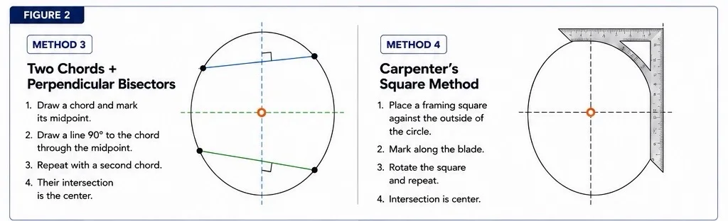
Finding the Center Using Chords or a Carpenter’s Square: Use perpendicular bisectors from two chords, or rotate a square around the circle to establish intersecting centerlines.
This is one of the most useful geometric methods because you do not need to know the diameter beforehand.
Draw a straight line connecting any two points on the circumference. This is called a chord.
Measure that chord and mark its midpoint.
From the midpoint, establish a line exactly 90° to the chord.
Now make a second chord somewhere else on the circle. Find its midpoint and again establish a perpendicular line.
Extend the two perpendicular lines until they intersect.
Their intersection is the center of the circle.
Why does this work?
The center of a circle always lies on the perpendicular bisector of every chord in that circle. One chord gives you a line on which the center must exist. A second chord gives you another line. Where those two lines cross is the only point satisfying both conditions.
This is one of the most dependable field methods when the center isn’t already known.
4. The Carpenter’s Square Method
A framing square or other accurate 90° square can provide a fast way to locate center on many round objects.
Position the square so the inside 90° corner and its legs establish reference points against the circle. Mark the resulting reference and construct the line that passes through the appropriate diagonal relationship.
Repeat the setup from another position around the circle.
The intersection of the two centerlines identifies the center.
The exact procedure depends on the type of square and whether you are working with the outside diameter of plate, pipe, or another circular component, so always verify the result with a second independent measurement.
This is especially useful when a square is already in your tool bag and extreme precision isn’t required.
5. Use a Straightedge and Equal Measurements
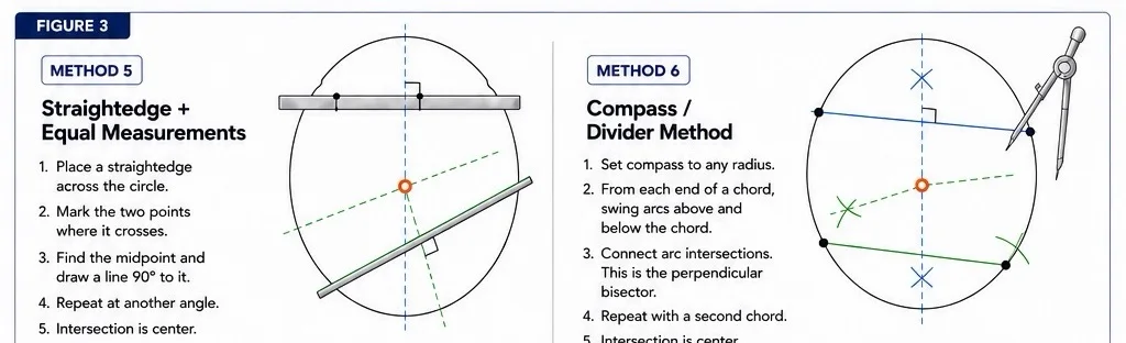
Finding the Center Using a Straightedge or Compass: Establish perpendicular bisectors from two different chords; where the constructed lines intersect is the center of the circle.
Sometimes you have limited tools but can still establish center using symmetry.
Place a straightedge across the circle to create a chord.
Mark the two points where the straightedge crosses the circumference.
Measure between those points and mark exactly half the distance.
Repeat the process with another chord at a noticeably different angle.
From the midpoint of each chord, establish a perpendicular line.
Where the perpendicular lines intersect is center.
This is essentially the chord method performed with basic field tools.
6. Compass Method
A compass or divider makes geometric center finding extremely accurate.
Create a chord by marking two points on the circumference. Without changing the compass opening, swing arcs from both ends of the chord—one set above the chord and another below it.
Connect the two points where those arcs intersect.
That line is the perpendicular bisector of the chord.
Repeat the process using another chord.
The two perpendicular bisectors intersect at the exact theoretical center of the circle.
This technique eliminates much of the guesswork involved in trying to establish 90° manually.
7. Center-Finding Square
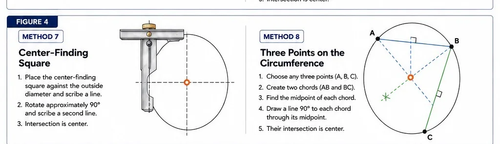
Finding the Center Using a Center-Finding Square or Three Points: Mark intersecting centerlines with a center finder, or use perpendicular bisectors from three points on the circumference to locate the exact center.
When repetitive fabrication work is involved, a dedicated center-finding square is one of the fastest solutions.
Place the tool against the outside diameter and mark along its center blade.
Rotate the tool approximately 90° and mark another line.
The intersection of those two lines is the center.
For round stock, shafts, pipe, disks, and similar components, this can turn a several-minute layout into a matter of seconds.
Even when using a dedicated center finder, rotating the tool and checking the center from multiple positions is good practice.
8. Find Center Using Three Points on the Circumference
Suppose you can’t conveniently measure the complete diameter, but you can identify three points on the circumference.
Call them:
A, B, and C
Connect A to B to create one chord.
Connect B to C to create another chord.
Find the midpoint of each chord and establish a perpendicular bisector through each midpoint.
Where those perpendicular bisectors cross is the center.
This principle is extremely important because any three non-collinear points define a circle.
It is also the basic geometry behind determining the center and radius of an existing arc.
9. Finding the Center From Only a Partial Arc
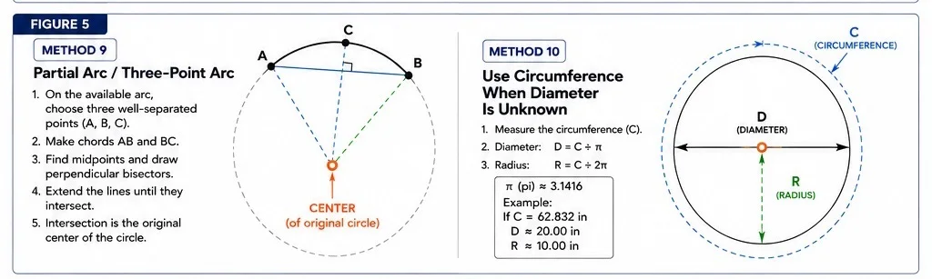
Finding the Center From a Partial Arc or Circumference: Use perpendicular bisectors to reconstruct the center of an incomplete circle, or calculate the diameter and radius from a known circumference.
Sometimes the entire circle doesn’t exist—or you simply can’t reach it.
Maybe you have a curved plate, pipe contour, tank shell layout, existing arc, or component where only part of the circumference is available.
You can still determine its original center.
Choose three well-separated points along the arc.
Connect the first and second points to create a chord.
Connect the second and third points to create another chord.
Find the midpoint of each chord.
Construct a perpendicular line through each midpoint.
Extend those lines.
Their intersection is the center of the circle that created the arc.
The farther apart your three points are along the available arc, generally the better your geometric construction will be. Points packed tightly together can magnify small measuring errors when the bisectors are extended.
10. Use the Circumference When the Diameter Is Unknown
Sometimes the circumference is easier to measure than the diameter, particularly around pipe, tanks, columns, or other large cylindrical equipment.
The relationship is:
C = πD
Therefore:
D = C ÷ π
And:
R = C ÷ 2π
Suppose the measured circumference is 62.832 inches.
D = 62.832 ÷ 3.1416
D ≈ 20 inches
Therefore:
R = 10 inches
Knowing the radius doesn’t automatically place the physical center for you, but it gives you a critical dimension that can be combined with straightedges, squares, levels, chords, or other layout references.
Which Method Should You Use?
For a complete circular plate or disk, measuring the diameter or using a center-finding square is usually fastest.
For an unknown circle, use two chords and perpendicular bisectors.
For only a partial arc, use three points and two perpendicular bisectors.
For precision geometric layout, use a compass/divider construction.
For repetitive shop fabrication, a center-finding square can save considerable time.
The important lesson isn’t memorizing one trick. It’s understanding the geometry well enough that you can reproduce center even when your preferred tool isn’t available.
Field Accuracy: Don’t Trust One Mark
A common layout mistake is finding what appears to be center once and immediately drilling, cutting, or fitting from it.
Verify it.
If you used two chords, create a third chord and construct another perpendicular bisector. That third line should pass through the same center point.
If you measured the diameter, check it from another direction.
If you’re using a center finder, rotate it and make a third line.
Instead of producing three noticeably different intersections, accurate layout should create a very small cluster of marks.
The tighter that cluster, the more confidence you have in the center.
A Useful Accuracy Principle
The geometry can be perfect while the physical layout is still wrong.
Soapstone line thickness, tape-hook movement, damaged squares, irregular plate edges, pipe ovality, scale, weld buildup, torch-cut edges, and poor viewing angle can all introduce error.
On rough material, don’t automatically treat one high spot on the edge as the true circumference. Establish the best representation of the actual circle and verify your center from multiple directions.
For precision work, use a fine scribe rather than a thick soapstone line whenever the material and work procedure allow it.
Why This Matters in Industrial Work
Finding center is the starting point for far more advanced layout.
Once the center is established, you can accurately locate quadrants, divide circumference, establish bolt patterns, lay out holes, locate nozzles, construct radial lines, transfer elevations, establish reference axes, and perform more advanced pipe and structural layouts.
The same geometry appears repeatedly in pipefitting, welding, fabrication, millwright work, ironwork, machining, tank work, and industrial construction.
A worker who understands why the chord method works doesn’t have to memorize every possible field situation.
They can rebuild the solution from basic geometry.
The Rule Worth Remembering
If you remember only one technique, remember this:
Draw a chord. Find its midpoint. Draw a 90° line through that midpoint. Do it again somewhere else. Where the two perpendicular lines intersect is center.
That principle works even when the center isn’t marked, the diameter isn’t known, and only part of the original circle is available.
That is the difference between simply knowing a layout trick and understanding the geometry behind the work.
Continue Learning: After mastering circle centers, continue through the Næxon Learning Center with circumference and diameter calculations, pipe layout, saddle layouts, flange clocking, offsets, pipefitter math, and other industrial field-layout techniques.


