Næxon Learning Center | Industrial Pipefitting
A dummy leg looks simple: a piece of pipe attached to a piping component and extended down to steel or another supporting surface. But laying one out correctly requires more than measuring the distance from the pipe to the steel and cutting a piece.
The critical question is:
Where is your measurement being taken from?
In the field, a dummy-leg dimension may be established from the bottom of the pipe, centerline of the pipe, or top of the pipe. Those three measurements are not interchangeable. If you don’t establish the reference point before calculating the dummy leg, the finished support can be off by approximately one pipe radius—or even one full pipe outside diameter.
This lesson covers the geometry and field procedure for calculating and laying out dummy legs using all three reference methods.
1. What Is a Pipe Dummy Leg?
A dummy leg is a structural pipe support made from a piece of pipe or similar round section attached to the process piping and extended to a supporting structure.
Depending on the piping design, a dummy leg may be attached to a straight run, elbow, or another approved attachment location. Dummy legs are commonly encountered around pipe racks, equipment piping, refinery units, process piping, and other industrial systems.
The dummy leg does not normally carry process flow. Its purpose is support.
A typical arrangement might look like this:
Process Pipe → Elbow → Dummy Leg → Structural Steel
The piping design and support detail determine the dummy-leg size, attachment location, reinforcement requirements, weld requirements, and whether the support is intended to carry vertical load, control movement, or perform another function.
A pipefitter’s job is to build the support according to those requirements—not simply make a piece of pipe fit underneath the line.
2. The Three Measurements Every Fitter Must Understand
Before doing any calculations, establish the reference used on the drawing or field measurement.
The three important references are:
TOP — Top of Pipe
CL/COP — Centerline or Center of Pipe
BOP — Bottom of Pipe
For a horizontal round pipe, these locations are related directly to the pipe’s actual outside diameter (OD).
If:
OD = actual pipe outside diameter
then:
Radius = OD ÷ 2
Therefore:
TOP = CL + Radius
and:
BOP = CL − Radius
The distance from TOP to BOP is one complete outside diameter.
This sounds elementary, but it becomes extremely important when calculating dummy legs.
3. Use Outside Diameter — Not Nominal Pipe Size
One of the easiest mistakes is treating nominal pipe size as the actual outside diameter.
For example, a nominal 8-inch pipe does not have an 8-inch OD.
Its actual OD is:
8.625 inches
Therefore its radius is:
8.625 ÷ 2 = 4.3125 inches
or:
4 5/16 inches
That 5/16-inch difference between an assumed 4-inch radius and the actual 4 5/16-inch radius matters when you’re trying to make a support land at the correct elevation.
Always calculate from the actual OD of the pipe specified for the job.
4. Bottom-of-Pipe Dummy-Leg Measurement
Let’s start with the easiest field reference.
Suppose the drawing establishes the elevation of the bottom of the process pipe and you know the elevation of the structural steel where the dummy leg lands.
For a simplified vertical support:
BOP elevation − Support elevation = vertical distance from BOP to support
Example:
Bottom of process pipe:
EL. 112’-6”
Top of supporting steel:
EL. 108’-0”
Difference:
112’-6” − 108’-0” = 4’-6”
So there are 4’-6” vertically between the bottom of the process pipe and the supporting steel.
However, this does not automatically mean you cut the dummy-leg pipe exactly 4’-6”.
Why?
Because the actual cut length depends on how the dummy leg intersects the process pipe.
If the upper end is saddled or contoured around another round surface, part of the support extends above the lowest point of the process pipe.
You therefore have to distinguish between:
reference dimension and actual cut geometry.
That distinction is one of the most important concepts in dummy-leg layout.
5. Center-of-Pipe Dummy-Leg Measurement
Centerline dimensions are extremely common in piping fabrication.
Suppose instead of BOP, the drawing gives the process-pipe centerline elevation.
Example:
Process pipe CL:
EL. 112’-10 5/16”
Process pipe:
8-inch NPS
Actual OD:
8 5/8”
Radius:
4 5/16”
Supporting steel:
EL. 108’-0”
The centerline-to-support dimension is:
112’-10 5/16” − 108’-0”
which gives:
4’-10 5/16”
But the dummy leg isn’t normally terminating at the center of the process pipe.
The bottom of the process pipe is one radius below centerline.
Therefore:
BOP = CL − pipe radius
So:
4’-10 5/16” − 4 5/16” = 4’-6”
We arrive at the same BOP-to-support dimension:
4’-6”
This is why knowing the reference point is critical.
6. Top-of-Pipe Dummy-Leg Measurement
Sometimes the available field dimension or drawing elevation references TOP.
Using the same 8-inch process pipe:
OD:
8 5/8”
Radius:
4 5/16”
Suppose TOP is:
EL. 113’-2 5/8”
Supporting steel is:
EL. 108’-0”
TOP-to-support distance:
5’-2 5/8”
To convert TOP to BOP, subtract the entire process-pipe OD:
5’-2 5/8” − 8 5/8” = 4’-6”
Again:
BOP-to-support = 4’-6”
All three methods describe the same physical pipe position.
The only thing changing is the reference.
7. The Three Methods Side by Side
Using our 8-inch process-pipe example:
TOP-to-steel = 5’-2 5/8”
CL-to-steel = 4’-10 5/16”
BOP-to-steel = 4’-6”
Notice the relationship.
From TOP to CL:
Subtract one radius.
From CL to BOP:
Subtract one radius.
From TOP directly to BOP:
Subtract one OD.
Going upward reverses the operation.
From BOP to CL:
Add one radius.
From CL to TOP:
Add one radius.
From BOP directly to TOP:
Add one OD.
If you can move confidently between these three reference points, many piping elevation calculations become much easier.
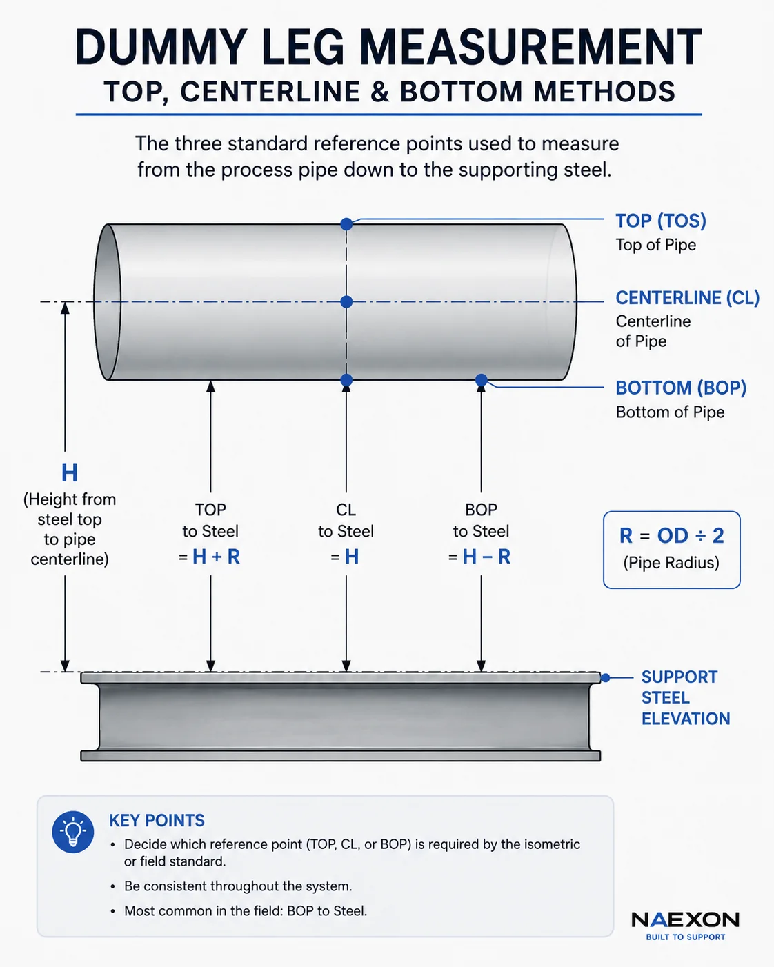
Figure — TOP, centerline (CL), and bottom-of-pipe (BOP) reference methods used to establish dummy-leg dimensions from the process pipe to the supporting steel.
8. But What Is the Actual Dummy-Leg Cut Length?
This is where dummy-leg work becomes more interesting.
Imagine a vertical dummy leg intersecting the underside of a horizontal pipe.
The top of the dummy leg may require a curved contour.
The center/high point of that contour reaches farther upward than the outside edges.
Therefore you cannot blindly take the BOP-to-steel dimension and call it the finished cut length everywhere around the dummy leg.
You first establish the required finished support position and then lay out the intersection between the two cylindrical surfaces.
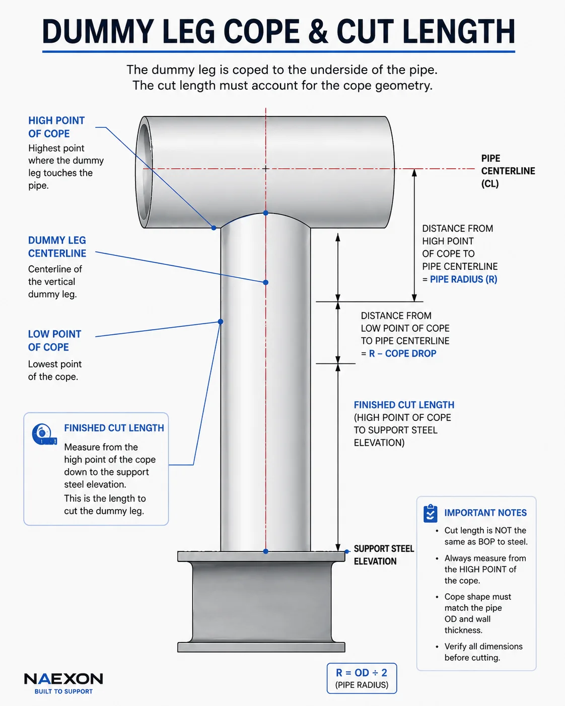
Figure — Dummy-leg cope and cut-length geometry showing the high and low points of the cope, centerline, and finished support elevation.
The geometry depends on:
- Process-pipe OD
- Dummy-leg OD
- Angle of intersection
- Exact attachment location
- Support elevation
- Required weld/detail
- Whether the supporting surface is level
- Whether the process pipe is level, sloped, or vertical
A 90-degree intersection between two round pipes creates a different contour than an angled intersection.
9. Center of the Dummy Leg
Another centerline matters here:
the centerline of the dummy leg itself.
When the dummy leg is vertical, establish its centerline before laying out the saddle.
That centerline needs to correspond with the required attachment location on the process piping.
If the leg is supposed to be directly underneath the process-pipe centerline, then viewed from the end, the two centerlines should align vertically.
This gives you a reliable datum for laying out the contour.
A fitter should avoid laying out the entire support from random outside surfaces.
Centerlines establish geometry.
Outside surfaces are then calculated from those centerlines.
10. Bottom, Center, and Top of the Dummy-Leg Pipe
There is another important distinction.
So far we’ve discussed TOP, CL, and BOP of the supported process pipe.
But the dummy leg itself is also round.
Looking at the dummy leg horizontally, it also has:
Top/upper tangent
Centerline
Bottom/lower tangent
The relationship is exactly the same:
Dummy-leg radius = Dummy-leg OD ÷ 2
Therefore:
Dummy-leg top = Dummy-leg CL + radius
and:
Dummy-leg bottom = Dummy-leg CL − radius
This becomes important when locating a dummy leg from a horizontal offset dimension.
If the drawing gives the dummy-leg centerline but you’re measuring from its outside edge, you must add or subtract the dummy-leg radius.
11. Example: Locating a 6-Inch Dummy Leg by Centerline
Suppose the drawing requires the centerline of a 6-inch dummy leg to be:
2’-0” from a known structural reference.
A 6-inch NPS pipe has an actual OD of:
6.625”
Radius:
3.3125”
or:
3 5/16”
If you need the near outside edge of the dummy leg:
24” − 3 5/16” = 20 11/16”
If you need the far outside edge:
24” + 3 5/16” = 27 5/16”
Therefore:
Near side = 1’-8 11/16”
Center = 2’-0”
Far side = 2’-3 5/16”
Three different tape measurements locate the same dummy leg.
Again, the question is:
Are you measuring the bottom/near tangent, center, or top/far tangent?
12. Dummy Leg Coming Off an Elbow
Dummy legs installed at elbows require additional attention because the elbow surface is curved in more than one direction.
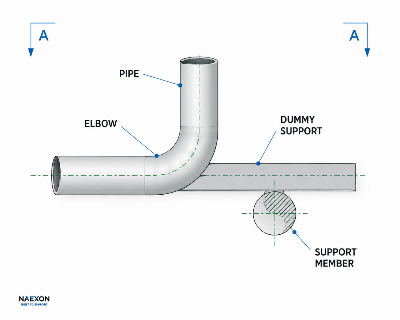
Figure 1 — Typical dummy support arrangement at a 90° elbow, showing the pipe, elbow, dummy support, centerlines, and structural support member.
You cannot treat an elbow exactly like a straight horizontal pipe.
First establish the elbow’s geometry:
Elbow centerline
Center of curvature
Tangent points
Required dummy-leg attachment location
Support elevation
If the support detail locates the dummy leg from the elbow centerline, maintain that centerline reference throughout your calculation.
Don’t start with centerline dimensions and then switch to outside-surface measurements without accounting for the radius.
This is where seemingly small errors become large field-fit problems.
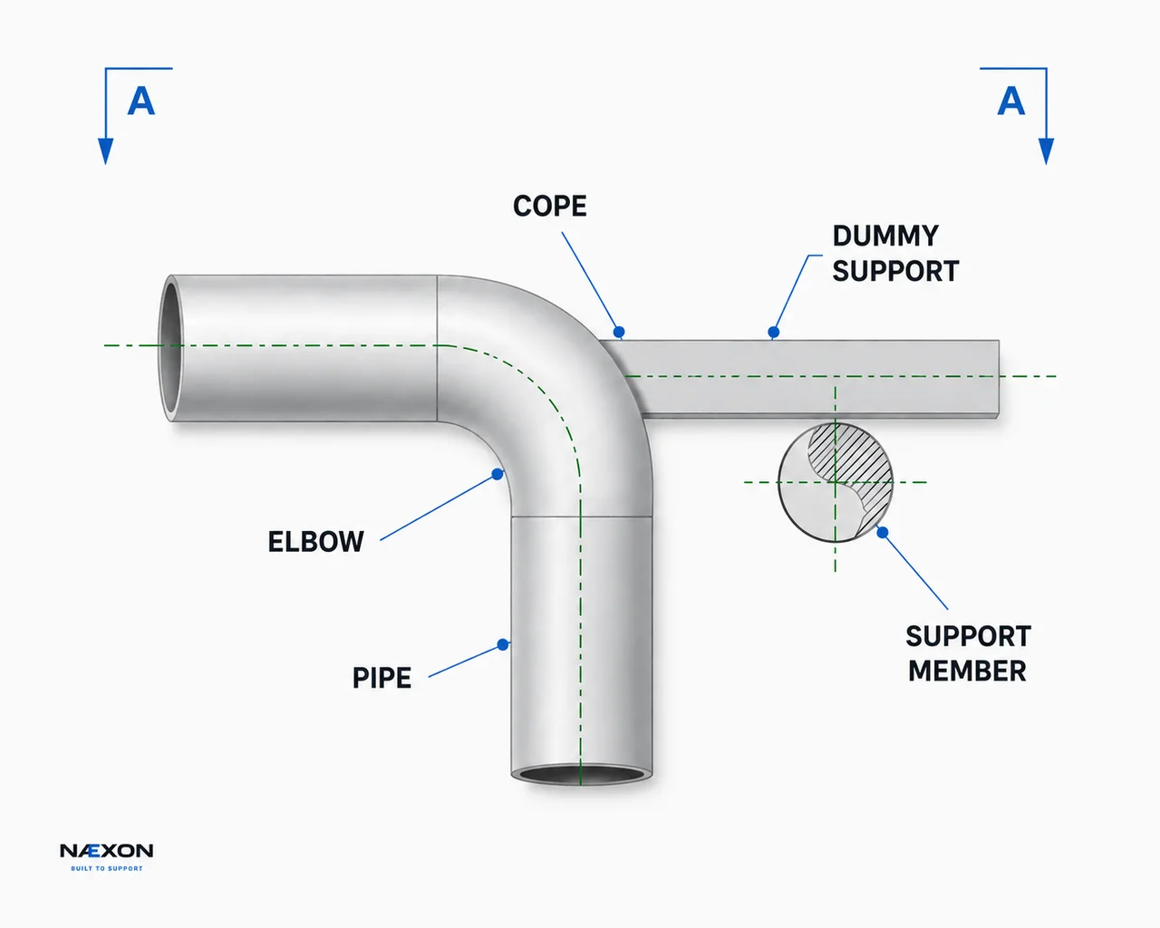
Figure 1 — Typical elbow dummy-leg support showing the cope, centerline alignment, dummy support, and structural support member.
13. Long-Radius Elbows and Centerline Radius
For a standard long-radius 90-degree elbow, the nominal centerline radius is commonly:
1.5 × nominal pipe size
For example, an 8-inch long-radius elbow has a nominal centerline radius of:
8 × 1.5 = 12 inches
But don’t confuse elbow centerline radius with pipe radius.
They describe two completely different things.
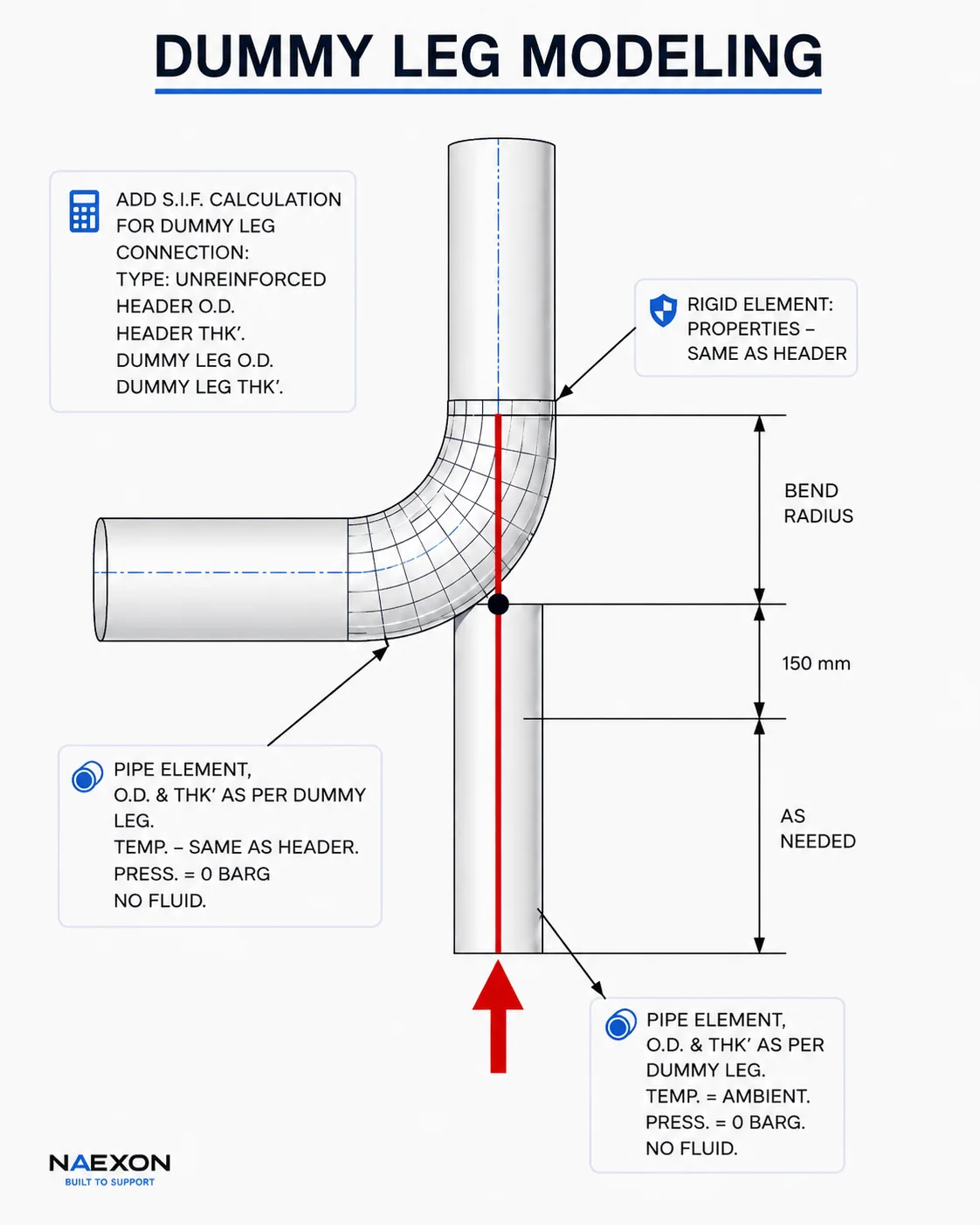
Figure 3 — Dummy-leg modeling at a 90° elbow showing bend radius, attachment point, and support geometry.
For 8-inch pipe:
Pipe OD:
8.625”
Pipe radius:
4.3125”
Typical LR elbow centerline radius:
12”
The 4.3125-inch radius moves you between TOP/BOP and pipe centerline.
The 12-inch elbow centerline radius describes the bend geometry.
Mixing those two dimensions will destroy the layout.
14. Field Method for Establishing a Dummy Leg
Before cutting anything, identify four things:
1. Supported pipe centerline/elevation
Determine the actual location of the piping.
2. Dummy-leg centerline
Establish exactly where the support attaches.
3. Landing elevation
Determine the actual elevation of the steel, shoe, plate, or structural member supporting the dummy leg.
4. Attachment geometry
Determine how the dummy leg intersects the piping and what contour/detail is required.
Once those four items are established, the support becomes a geometry problem instead of guesswork.
15. Measuring an Existing Pipe in the Field
Sometimes you won’t have a convenient centerline elevation.
Instead, you’ll physically measure the pipe.
If you can obtain BOP, you can calculate CL:
CL = BOP + pipe radius
If you can obtain TOP:
CL = TOP − pipe radius
If you know TOP and need BOP:
BOP = TOP − pipe OD
If you know BOP and need TOP:
TOP = BOP + pipe OD
This allows you to convert field measurements into the centerline dimensions normally used for fabrication.
16. Example: Field Measurement From Bottom of Pipe
Suppose you measure from the structural steel to the bottom of a 10-inch process pipe and get:
3’-9 1/4”
10-inch NPS pipe OD:
10.750”
Radius:
5.375” = 5 3/8”
Centerline-to-steel becomes:
3’-9 1/4” + 5 3/8”
Convert:
45 1/4” + 5 3/8”
45 2/8” + 5 3/8” = 50 5/8”
Therefore:
CL-to-steel = 4’-2 5/8”
TOP-to-steel becomes:
4’-2 5/8” + 5 3/8” = 4’-8”
So:
BOP = 3’-9 1/4”
CL = 4’-2 5/8”
TOP = 4’-8”
All three are simply different descriptions of the exact same pipe elevation.
17. Checking the Dummy Leg Before Welding
Before final welding, check the support from more than one reference.
Verify the process-pipe elevation.
Verify the dummy-leg location.
Verify the support landing elevation.
Check the dummy leg for plumb in two directions when it is designed to be vertical.
Confirm that the contour fits correctly.
Confirm the support isn’t unintentionally pushing or pulling the process pipe out of position.
And most importantly, verify the drawing and approved support detail.
A dummy leg should support the piping in its designed position—not force incorrectly positioned piping into place.
18. Common Dummy-Leg Mistakes
One of the most common mistakes is using nominal pipe size as actual OD.
Another is confusing centerline elevation with BOP elevation.
A third is measuring TOP in the field and treating that number as CL.
Another is forgetting that the contoured end changes the physical cut geometry.
Fitters can also get into trouble by locating the support from the outside edge of the dummy leg when the drawing specifies its centerline.
And on elbows, confusing pipe radius with elbow centerline radius can create a major error.
The cure for almost all of these problems is the same:
Mark your reference before doing the math.
Write down:
TOP
CL
or
BOP
beside the dimension.
Don’t leave it in your head.
19. A Simple Field Rule
Remember this relationship:
TOP
↓ subtract pipe radius
CENTERLINE
↓ subtract pipe radius
BOTTOM
Or:
TOP − OD = BOP
Going upward:
BOTTOM
↑ add pipe radius
CENTERLINE
↑ add pipe radius
TOP
This works for any round pipe as long as you’re using the correct actual outside diameter.
20. Dummy-Leg Field Example
Suppose you are installing a dummy leg beneath an 8-inch process line.
Process-pipe CL elevation:
EL. 125’-4 5/16”
Steel elevation:
EL. 120’-10”
Pipe OD:
8 5/8”
Pipe radius:
4 5/16”
First determine BOP:
125’-4 5/16” − 4 5/16”
BOP = EL. 125’-0”
Now determine the vertical distance from BOP to steel:
125’-0” − 120’-10”
= 4’-2”
Now check from TOP.
TOP:
125’-4 5/16” + 4 5/16”
= EL. 125’-8 5/8”
TOP-to-steel:
125’-8 5/8” − 120’-10”
= 4’-10 5/8”
Subtract one complete OD:
4’-10 5/8” − 8 5/8”
= 4’-2”
Same answer.
That second calculation is an excellent field check.
21. Why Experienced Fitters Work From Centerlines
Centerline dimensions remove much of the confusion caused by different pipe diameters.
Piping drawings, isometrics, elevations, fittings, elbows, offsets, and equipment connections are fundamentally organized around centerline geometry.
Once the centerline is established, the outside surfaces can be calculated.
That is why a strong pipefitter learns to think:
Centerline first.
Then convert to:
TOP, BOP, near side, far side, or whatever physical surface is needed for the field measurement.
22. The Rule to Remember
When laying out a dummy leg, never begin by asking:
“How long do I cut it?”
First ask:
“What is my reference?”
Is the dimension to:
Bottom of pipe?
Center of pipe?
Top of pipe?
Then identify the actual pipe OD, calculate the radius, establish the dummy-leg centerline and landing elevation, and determine the actual intersection geometry.
The basic relationship is simple:
Radius = OD ÷ 2
BOP + Radius = CL
CL + Radius = TOP
BOP + OD = TOP
Once those relationships become automatic, dummy-leg elevations and field measurements become much easier to calculate—and much harder to get wrong.
Næxon Learning Center — Built for the people who build it.


