Learn | Fundamentals • Equipment & Components • Pipefitting
A flange can tell you a surprising amount about itself before you ever look at a drawing, material list, or specification. The markings stamped around the outside edge can identify its size, pressure class, material grade, specification, manufacturer, and sometimes heat or traceability information.
For pipefitters, welders, inspectors, and anyone handling industrial piping, knowing how to read these markings is a basic but important field skill. A flange may physically bolt up and still be the wrong flange for the service. Understanding the stamp helps you verify that the component in your hands matches the drawings, piping specification, and material requirements.
What Flange Markings Can Tell You
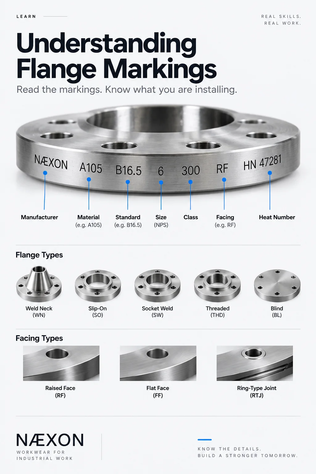
Depending on the manufacturer and specification, a flange may contain markings such as:
Manufacturer → Material → Specification → Size → Pressure Class → Heat Number → Additional Codes
For example, imagine seeing:
NÆXON | A105 | B16.5 | 6 | 300 | HN 47281
That information could be interpreted as:
A105 — forged carbon-steel material specification
B16.5 — dimensional standard
6 — nominal pipe size
300 — pressure class
HN 47281 — heat or traceability identification
The exact arrangement varies. Never assume every manufacturer stamps information in the same order.
1. Nominal Pipe Size
One of the first things to identify is the flange size.
You may see markings such as:
2
4
6
8
12
These normally refer to Nominal Pipe Size (NPS) rather than the actual measured outside diameter.
For example:
6-inch NPS pipe does not have a 6-inch outside diameter.
Its actual OD is 6.625 inches.
This distinction becomes especially important when checking flange dimensions or matching components in the field.
Field Rule
Nominal size identifies the piping system size—not necessarily the physical OD you will measure with a tape.
2. Pressure Class
You will commonly see:
150
300
400
600
900
1500
2500
These numbers identify the flange’s pressure class.
A marking such as:
6 300
generally indicates a 6-inch Class 300 flange.
One common mistake is treating Class 300 as meaning the flange is simply rated for exactly 300 psi.
It does not work that way.
The allowable pressure depends on several factors, particularly:
material + operating temperature + applicable pressure-temperature rating
As temperature increases, allowable working pressure will generally change.
Field Rule
Pressure class is a flange classification—not a direct statement of allowable operating PSI.
Always use the applicable piping specification and pressure-temperature tables when determining allowable service conditions.
3. Material Specification
The material marking is one of the most important things to verify.
A common carbon-steel forged flange might show:
A105
This generally refers to ASTM A105/A105M, a specification covering forged carbon-steel piping components.
But industrial piping systems can contain many other materials.
You might encounter markings associated with:
carbon steel
low-temperature carbon steel
stainless steel
chrome-moly/alloy steel
nickel alloys
other project-specific materials
Never identify a flange only by its appearance.
Two flanges can look nearly identical while having very different metallurgy and service requirements.
Field Rule
If metallurgy matters, read the markings—don’t judge the flange by color or appearance.
4. Stainless-Steel Grade Markings
Stainless flanges may carry markings identifying grades such as:
F304
F304L
F316
F316L
The L indicates a low-carbon version of the stainless grade.
This becomes important because the project’s welding procedure, filler metal requirements, corrosion service, material control system, and piping specification may depend on the exact grade.
A flange marked F316L should not automatically be treated as interchangeable with one marked F304L simply because both are stainless steel.
5. Alloy-Steel Markings
High-temperature piping systems may use alloy materials rather than ordinary carbon steel.
Depending on the system, you may encounter forged-component grades such as:
F11
F22
F91
These materials may appear in high-temperature process or power-generation piping.
Material control becomes especially important here.
Putting the wrong alloy flange into a piping system can create a serious material-compliance problem even when the dimensions are identical.
This is one reason industrial projects may use Positive Material Identification (PMI) in addition to checking stamped markings and documentation.
6. ASME B16.5
Another marking you may encounter is:
B16.5
ASME B16.5 covers many common pipe flanges and flanged fittings within its specified size and class ranges.
This standard establishes requirements involving areas such as flange dimensions, tolerances, facing dimensions and pressure-temperature ratings.
Do not confuse:
ASME B16.5
with:
ASTM A105
They describe different things.
Think of it this way:
ASTM A105 → What material is it?
ASME B16.5 → What dimensional/flange standard does it conform to?
That distinction is worth remembering.
7. Heat Number and Traceability
A flange may also have a heat number, heat code, lot number, or another traceability identifier.
Example:
HEAT 74291
This can connect the physical component to its material documentation.
On controlled industrial projects, that traceability can be extremely important.
The paperwork may contain information relating to:
chemical composition
mechanical properties
material specification
heat treatment
testing
manufacturing information
The physical marking therefore becomes part of the chain connecting the flange installed in the field to its material records.
Field Rule
Protect traceability.
Grinding away identification markings or losing component identification can create major problems for material control and quality assurance.
8. Manufacturer Identification
Flanges normally carry manufacturer identification or a manufacturer’s trademark.
This allows the component to be traced back to its producer and associated manufacturing records.
The manufacturer’s mark should not be confused with the material grade.
For example, several groups of markings around the flange rim might represent:
Manufacturer | A105 | 6 | 300 | B16.5 | Heat 74291
Each marking serves a different purpose.
9. Flange Type May Require Visual Verification
Do not depend entirely on the stamping to determine flange configuration.
Common flange types include:
Weld Neck (WN) — recognizable by its tapered hub.
Slip-On (SO) — pipe slips through the flange before welding.
Socket Weld (SW) — pipe seats inside an internal socket.
Threaded (THD) — flange contains internal pipe threads.
Blind (BL) — solid flange used to close the end of a piping system.
Some manufacturers include type information in their markings, but the fitter should still know how to identify the physical configuration.
10. Raised Face, Flat Face and RTJ
You also need to identify the flange facing.
Raised Face — RF
The gasket seating area is raised above the surrounding flange face.
Flat Face — FF
The gasket seating surface is essentially in the same plane across the flange face.
Ring-Type Joint — RTJ
The flange contains a machined groove designed for a metallic ring gasket.
Facing matters.
A flange being the correct size, class and material does not automatically mean it has the correct facing for the piping system.
Reading a Flange in the Field
Suppose you pick up a flange carrying markings that indicate:
8 | 600 | A105 | B16.5 | HN 58342
Before installation, you can begin identifying it as:
Nominal size: 8-inch
Pressure class: Class 600
Material: ASTM A105 forged carbon steel
Standard: ASME B16.5
Traceability: Heat/identification number 58342
But your inspection should not stop there.
You still need to verify the required:
flange type
facing
bore
pipe schedule compatibility where applicable
material requirements
project piping specification
drawing/isometric requirements
The Bore Is Especially Important on Weld-Neck Flanges
This is an easy detail to overlook.
Two weld-neck flanges can have the same:
NPS + Class + Material
and still have different bores intended to match different pipe wall thicknesses.
For example, a flange intended for one pipe schedule may not have the same bore as one prepared for a heavier-wall pipe.
Before welding a weld-neck flange, verify that the bore and required end preparation are correct for the pipe and project specification.
A flange being 6-inch Class 300 A105 does not by itself tell you everything needed to weld it into the system.
A Simple Flange Verification Routine
Before installing a flange, develop the habit of checking:
SIZE → CLASS → MATERIAL → TYPE → FACE → BORE → TRACEABILITY → SPEC
Then compare what is physically in your hands against the isometric drawing, piping material specification and applicable project requirements.
That simple routine can catch the wrong component before it becomes a welded, inspected and much more expensive problem.
Common Mistakes
Assuming Class 150 Means 150 PSI
It doesn’t. Pressure class must be interpreted using the applicable material and temperature ratings.
Checking Size but Ignoring Material
A carbon-steel and alloy flange can have matching dimensions while being completely different from a metallurgy standpoint.
Ignoring the Bore
Especially dangerous with weld-neck flanges and heavier-wall piping.
Assuming Stainless Is Stainless
304/304L and 316/316L are not automatically interchangeable.
Losing Traceability
Removing or destroying markings can break the material-identification chain required by the project.
Installing by Appearance Alone
If the job has controlled materials, verify markings and documentation rather than relying on appearance.
Field Example
You’re building a spool from an isometric calling for:
6” — Class 300 — A105 — Weld Neck — Raised Face
A flange arrives at your work area.
It looks correct and the bolt pattern matches.
Before fitting it, you check the markings.
The flange shows the correct:
6-inch size
Class 300
A105 material
You visually confirm:
Weld-neck configuration
Raised-face configuration
Then you verify the bore against the required pipe wall/schedule and confirm its identification against the project’s material-control requirements.
Only after all of those checks does the flange truly become the flange you expected—not simply one that happens to fit.
Field Rule
Never let “it fits” become your material verification procedure.
A flange can have the correct bolt pattern and still have the wrong material, pressure class, facing, bore, or specification.
Read the steel before you weld the steel.
Knowledge Check
1. What does Class 300 mean?
It identifies the flange pressure class. It does not simply mean the flange has a maximum operating pressure of 300 psi.
2. What does A105 commonly identify?
A forged carbon-steel piping-component material specification.
3. What does B16.5 identify?
An ASME standard covering specified pipe flanges and flanged fittings.
4. Why is a heat number important?
It helps maintain material traceability.
5. Can two 6-inch Class 300 weld-neck flanges have different bores?
Yes. Their bores can be prepared for different pipe wall thicknesses.
6. Should flange material be identified by appearance alone?
No. Verify markings, documentation, and project material-control requirements.
Practical Exercise
The next time you have several flanges available in the field, select three different ones and record:
Nominal Size
Pressure Class
Material Grade
Flange Type
Facing
Bore
Manufacturer
Heat/Traceability Number
Then compare those observations against the applicable isometric or material specification.
The goal isn’t simply to memorize markings. It’s to develop the habit of looking at a flange and immediately asking:
What exactly am I about to install?
Continue Learning
Build on this lesson in the Næxon Learning Center with lessons on flange types, flange pressure classes, raised-face vs. flat-face vs. RTJ flanges, bolt-up practices, gasket selection, pipe schedules, material identification, and reading piping isometrics.


