Learning Center | Millwrights | Field Skill
A pump and its driver can look perfectly aligned from a few feet away and still be far enough out of alignment to create vibration, damage bearings, wear a coupling, and shorten mechanical-seal life. That is why alignment is one of the most important checks performed when installing, rebuilding, or returning rotating equipment to service.
For millwrights, alignment isn’t simply about making two shafts appear straight. The goal is to establish the correct relationship between the rotational centerlines of the pump and motor under the conditions specified for the equipment.
This lesson explains the fundamentals of pump and motor alignment, the difference between offset and angular misalignment, why soft foot matters, and the basic field workflow used before equipment is placed into service.
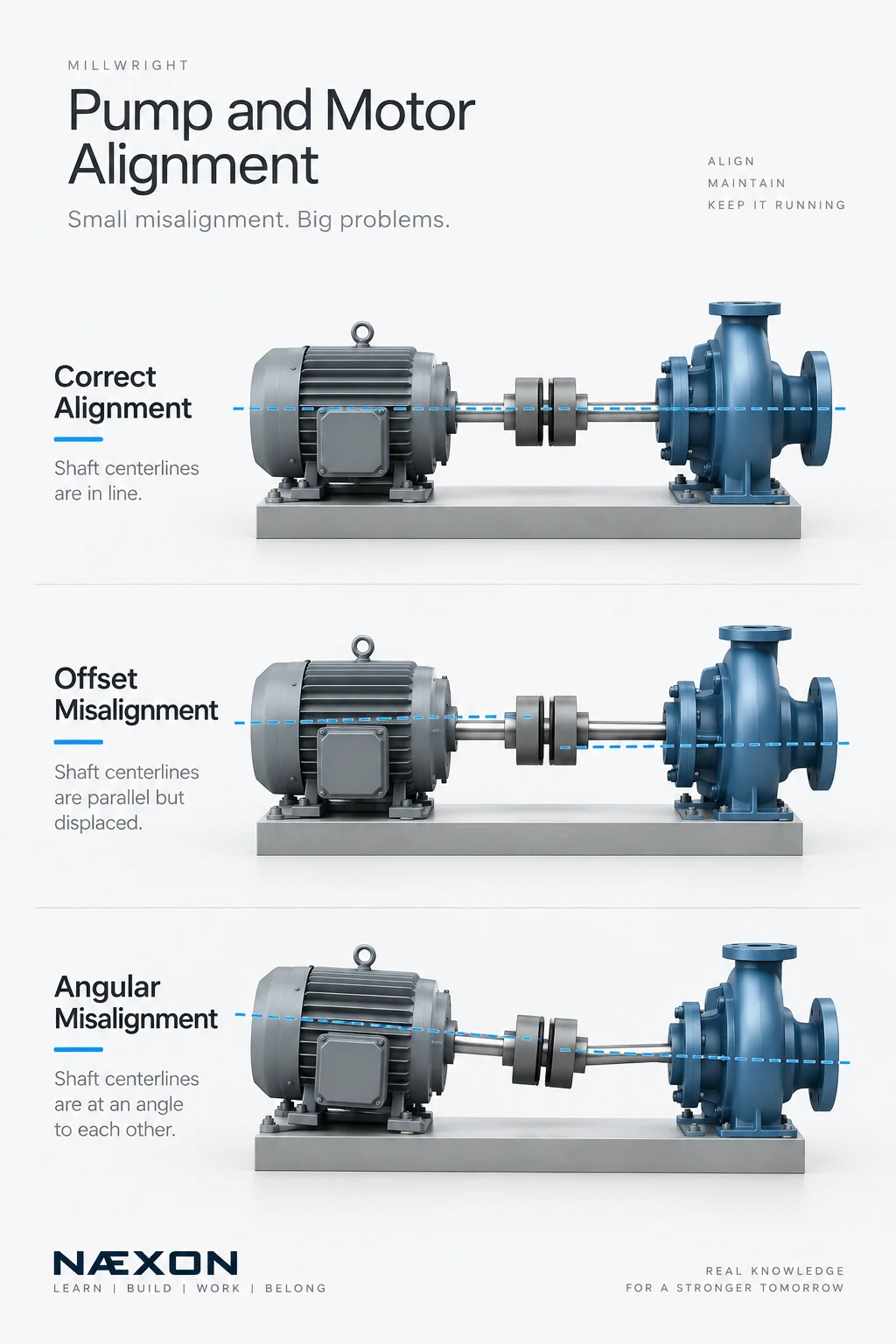
Pump and motor alignment fundamentals: correct alignment keeps shaft centerlines in line, while offset and angular misalignment can increase vibration, component wear, and the risk of premature equipment failure.
1. What Are We Actually Aligning?
Consider a typical centrifugal pump driven by an electric motor.
MOTOR → COUPLING → PUMP
The motor shaft and pump shaft meet through a coupling. Ideally, their rotational centerlines are positioned according to the equipment manufacturer’s required alignment condition.
The coupling can tolerate some movement, but that does not mean it should be used to compensate for poor alignment. A flexible coupling is primarily intended to transmit torque while accommodating limited movement within its design limits.
Alignment work therefore focuses on the shaft centerlines, not simply the outside surfaces of the coupling.
2. The Two Basic Types of Misalignment
Two conditions are especially important to understand: offset misalignment and angular misalignment.
Offset Misalignment
Offset, sometimes called parallel misalignment, occurs when the shaft centerlines are generally parallel but displaced from one another.
Think of two perfectly straight lines running beside each other:
──────── MOTOR
──────── PUMP
They point in the same direction, but they do not share the required centerline relationship.
Offset can occur vertically, horizontally, or as a combination of both.
Angular Misalignment
Angular misalignment occurs when the shaft centerlines are positioned at an angle relative to each other.
Conceptually:
MOTOR ────────╲
** ╲──────── PUMP**
Instead of maintaining the required relationship, the centerlines converge or diverge.
Real equipment frequently has both angular and offset misalignment at the same time, which is why alignment requires measurement rather than visual judgment.
3. Why Misalignment Matters
When a motor operates at hundreds or thousands of revolutions per minute, a small installation error can become a repetitive mechanical load.
Misalignment can contribute to increased vibration, coupling wear, bearing loading, mechanical-seal problems, elevated temperatures, loose fasteners, and premature equipment failure.
The equipment may still run. That doesn’t mean the alignment is acceptable.
A machine capable of operating while misaligned can continue accumulating damage until another component becomes the failure point.
4. Before Alignment: Check the Foundation and Machine Condition
Alignment should not begin with random adjustments to the motor.
First verify that the equipment installation itself is suitable for alignment. Depending on the job and equipment, this can include checking the baseplate, mounting surfaces, anchor bolts, machine feet, piping condition, coupling condition, shaft condition, and other installation requirements.
The pump is commonly treated as the stationary machine while corrections are made by moving the motor, but the actual procedure must follow the equipment design, project requirements, and approved alignment procedure.
Trying to align equipment that is sitting incorrectly on its base can turn into an endless cycle of measurements and corrections.
5. Check for Soft Foot
One of the most important preliminary checks is soft foot.
Soft foot exists when the machine feet do not sit correctly on their mounting surfaces. Tightening the hold-down bolts can then distort or reposition the machine.
Imagine a four-legged table with one leg slightly short. The table may rock until force is applied to it.
A motor can behave similarly.
If a millwright aligns the motor while soft foot is present, tightening the bolts can change the alignment that was just established.
Potential contributors include incorrect shimming, dirt or debris under a foot, damaged mounting surfaces, bent or distorted feet, excessive shim stacks, and other installation problems.
Correct the underlying condition rather than simply forcing the machine into position.
6. Understand Shims
Shims are used beneath machine feet to make controlled vertical corrections.
Adding or removing shim thickness changes the machine’s vertical position. The required correction depends on the measurements and geometry of the particular alignment.
Shims should be clean, flat, appropriate for the equipment, and installed according to the applicable procedure. Dirty, damaged, folded, or poorly installed shims can introduce additional error.
A good millwright treats the shim pack as part of the precision installation—not scrap metal used to fill a gap.
7. Rough Alignment Comes First
Before precision measurements begin, the motor and pump are normally brought reasonably close to the required position.
This is rough alignment.
Depending on the equipment and procedure, millwrights may use straightedges, feeler gauges, scales, or other basic methods during this stage.
Rough alignment gets the machine into a workable range. It should not automatically be treated as the final alignment.
A straightedge across coupling surfaces can be useful for preliminary positioning, but precision rotating equipment may require substantially more accurate measurement.
8. Precision Alignment Methods
Industrial alignment can be performed using several methods.
Dial indicators provide mechanical measurements that experienced millwrights can use to calculate machine corrections. Different indicator arrangements can be used depending on the equipment and procedure.
Laser shaft-alignment systems measure the relationship between the shafts electronically and can calculate required corrections at the movable machine’s feet.
Laser systems can make the process faster and easier to interpret, but the fundamentals still matter. A sophisticated instrument cannot compensate for poor mounting conditions, incorrect setup, unstable brackets, soft foot, or bad measurement practices.
The technician still needs to understand what the numbers mean.
9. Vertical and Horizontal Corrections
Alignment is generally considered in two planes.
Vertical correction is commonly accomplished through controlled changes to shim thickness beneath the movable machine’s feet.
Horizontal correction involves carefully repositioning the movable machine sideways using the approved adjustment method.
Corrections should be deliberate. Randomly moving the machine until the display turns green teaches very little about what is actually happening.
Measure. Determine the required correction. Move the machine. Tighten appropriately. Measure again.
10. Tightening Can Change Alignment
One of the easiest mistakes is obtaining acceptable measurements while the machine is loose and assuming the job is finished.
Bolt tightening can move the machine.
That is why alignment must be verified in the condition required by the applicable procedure. If the measurements change significantly after tightening, investigate why rather than repeatedly chasing the reading.
Possible causes include soft foot, poor shimming, movement during tightening, unstable mounting conditions, pipe strain, or another mechanical problem.
11. Pipe Strain Can Affect Pump Alignment
This is where millwright and pipefitter work directly intersect.
Connected piping should not be used to force a pump into position. Excessive forces from improperly fitted or supported piping can influence pump position and alignment.
A pump can be aligned correctly and then change when piping connections are made or disturbed.
That is why piping condition and machine alignment sometimes have to be evaluated together.
For more fundamentals on industrial piping, flange installation, fabrication, and mechanical systems, continue through the Næxon Learning Center and Næxon Resources sections.
12. Consider Operating Conditions
A machine’s position while cold and shut down may not be identical to its position at operating temperature.
Equipment can experience thermal growth as temperatures increase. Depending on the machine and service, the required cold alignment condition may therefore include specified offsets intended to produce the desired relationship during operation.
Never invent these values.
Use the equipment manufacturer’s requirements, engineering information, project specifications, or approved procedure for the machine being aligned.
13. Basic Field Workflow
A simplified alignment sequence may look like this:
Inspect → Check mounting → Check soft foot → Rough align → Set up measurement system → Measure → Correct vertical position → Correct horizontal position → Tighten → Re-measure → Document
The actual order and requirements can vary by equipment and procedure, but the principle remains consistent: establish a mechanically sound installation before attempting precision alignment.
Common Mistakes
A common mistake is assuming the coupling will compensate for poor alignment. Another is skipping the soft-foot check and immediately adding shims based on alignment readings.
Other problems include aligning dirty or unstable equipment, making uncontrolled machine movements, failing to verify readings after tightening, ignoring piping influence, confusing coupling alignment with shaft alignment, and using generic tolerances instead of the requirements applicable to the actual machine.
Precision alignment is a measurement process, not an eyeballing process.
Field Rule
Don’t try to precision-align a machine that isn’t mechanically stable.
If the base, feet, shims, piping, mounting surfaces, or measurement setup are moving, the readings cannot reliably represent the machine’s true condition.
Fix the mechanical problem first. Then align the equipment.
Knowledge Check
1. What are the two basic forms of shaft misalignment?
Offset and angular misalignment.
2. What is soft foot?
A condition in which the machine feet do not sit correctly on their mounting surfaces, allowing tightening forces to distort or reposition the machine.
3. Why shouldn’t a flexible coupling be treated as a solution for poor alignment?
Because the coupling is intended to transmit torque while accommodating only the movement and misalignment permitted by its design; excessive misalignment can load and damage the equipment.
4. Why should alignment be checked after tightening?
Because tightening the machine feet can change its position.
5. Why can connected piping matter during pump alignment?
Because excessive piping forces can influence the pump’s position and therefore affect shaft alignment.
Practical Exercise
Picture a motor driving a centrifugal pump.
The motor has four mounting feet. During the preliminary check, one foot does not make proper contact with its mounting surface. When that hold-down bolt is tightened, the alignment readings change.
Before attempting to correct the final shaft alignment, ask yourself:
What condition should be investigated first?
Answer: Soft foot.
Correct the mounting condition first, verify the machine is stable, and then continue with the approved alignment procedure.
Continue Learning
Pump alignment connects directly with several other industrial skills: coupling installation, bearings, mechanical seals, rotating-equipment vibration, pump fundamentals, precision measurement, lubrication, piping installation, and machinery troubleshooting.
Continue exploring the Næxon Learning Center for multi-craft industrial training and Næxon Resources for practical information covering refinery, petrochemical, pipeline, power-generation, LNG, shutdown, maintenance, and industrial-construction work.


