Pressure vessels and separators are everywhere in a refinery.
They may not be as visually dramatic as a fired heater, compressor, or distillation tower, but they perform one of the most important jobs in process operations:
They give different phases of a process stream a controlled place to separate.
A mixed stream entering a refinery separator may contain:
Gas + Hydrocarbon Liquid + Water
Inside the vessel, velocity decreases, gravity takes over, droplets settle or rise, and specially designed internals help separate the phases.
The basic process is:
Mixed Process Stream → Separator → Gas + Hydrocarbon Liquid + Water
For pipefitters, welders, operators, boilermakers, instrument technicians, inspectors, and maintenance personnel, understanding separators is essential because these vessels combine pressure containment, liquid level, gas pressure, process piping, relief protection, instrumentation, vessel internals, and potentially hazardous hydrocarbons in one system.
What Is a Pressure Vessel?
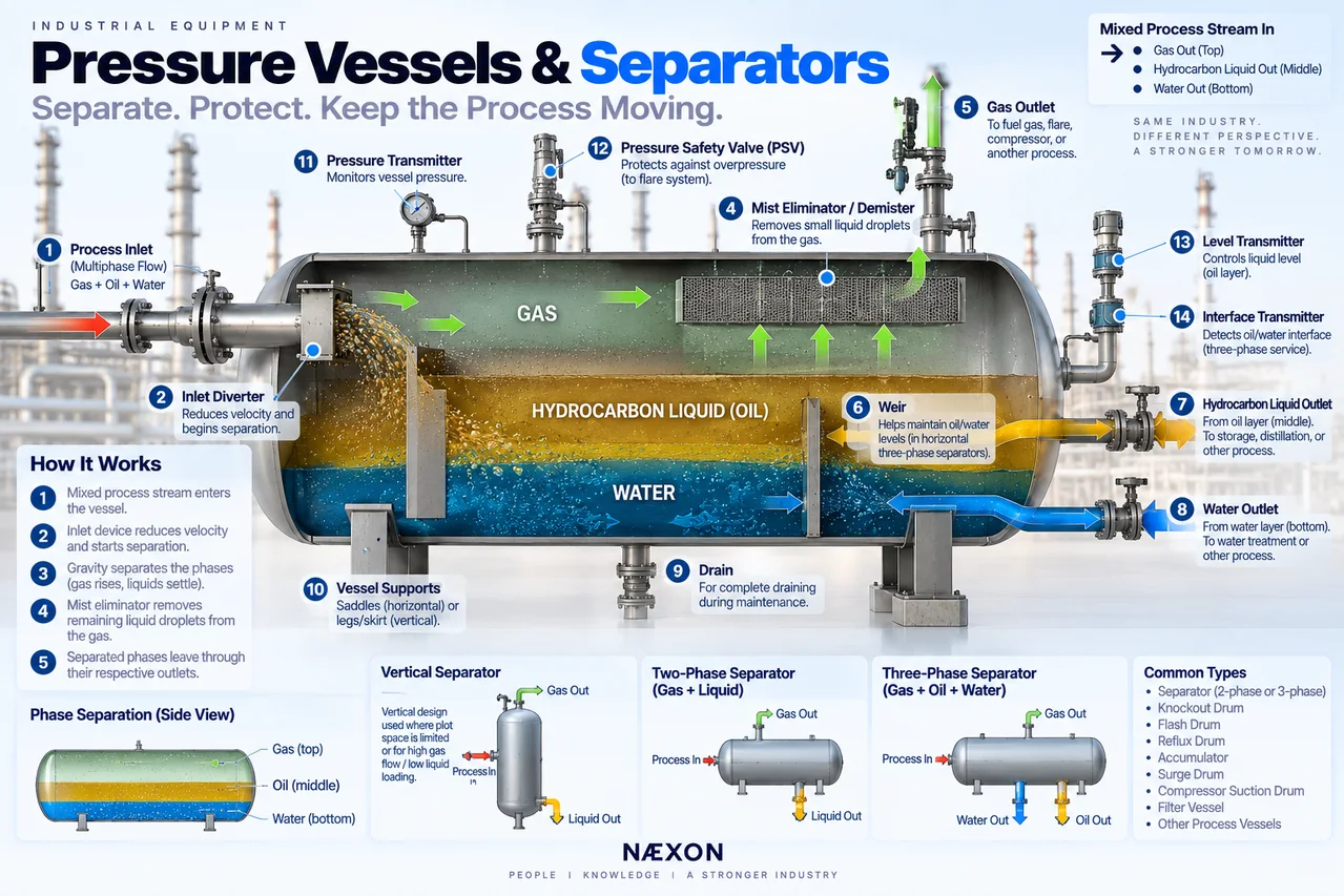
Figure: Cutaway view of a three-phase refinery separator showing how a mixed process stream is separated into gas, hydrocarbon liquid, and water using reduced velocity, gravity, internal weirs, and a mist eliminator, with dedicated outlets and instrumentation controlling each phase.
A pressure vessel is a container designed to safely contain fluids at pressures significantly different from atmospheric pressure.
In a refinery, pressure vessels perform many different functions.
They can be used as:
- Separators
- Knockout drums
- Flash drums
- Reflux drums
- Accumulators
- Surge drums
- Filter vessels
- Reactor vessels
- Compressor suction drums
- Compressor discharge drums
A separator is therefore a type of pressure vessel.
But:
Not every pressure vessel is a separator.
What Is a Separator?
A separator is a pressure vessel specifically designed to separate different phases contained in a process stream.
Those phases commonly include:
Gas
Hydrocarbon liquid
Water
Some separators handle only two phases.
Others handle three.
The vessel creates enough space and residence time for these materials to separate according to their physical properties.
The Basic Separation Principle
Imagine a process stream traveling rapidly through piping.
Inside that stream are:
- Gas
- Oil droplets
- Water droplets
While everything is moving rapidly through a pipe, separating those materials can be difficult.
Then the stream enters a much larger vessel.
The available flow area increases dramatically.
Velocity decreases.
Now gravity has time to work.
Generally:
Gas rises.
Liquid settles.
And when oil and water are present:
Lighter hydrocarbon remains above the heavier water phase.
The separator provides the controlled environment necessary for this to happen.
The Three Phases
Understanding density is the key to understanding many refinery separators.
Gas
Gas has the lowest density and moves toward the upper portion of the vessel.
Hydrocarbon Liquid
Hydrocarbon liquid settles below the gas but generally floats above water.
Water
Water is commonly the densest of the three phases and settles toward the bottom.
The simplified arrangement becomes:
Gas
↑
Hydrocarbon
↓
Water
Two-Phase Separator
A two-phase separator separates:
Gas + Liquid
The liquid may be hydrocarbon, water, or another process liquid.
The mixed stream enters the vessel.
Gas separates and exits through the upper gas outlet.
Liquid collects in the lower portion and exits through the liquid outlet.
Simplified:
Gas ↑
Mixed Feed → Separator
Liquid ↓
Three-Phase Separator
A three-phase separator separates:
Gas + Hydrocarbon Liquid + Water
This requires more sophisticated level control because the vessel must control not only the total liquid inventory but also the interface between oil and water.
Inside the vessel:
Gas occupies the upper space.
Oil forms an intermediate liquid layer.
Water settles underneath.
Each phase can then leave through its appropriate outlet.
Horizontal Separators
Horizontal separators are extremely common.
They look like large horizontal cylindrical vessels supported by saddles.
One major advantage is the large liquid surface area available inside the vessel.
This can provide good:
- Gas-liquid disengagement
- Liquid retention time
- Oil-water separation
- Surge capacity
Horizontal vessels are especially common in three-phase separation service.
Vertical Separators
Vertical separators stand upright.
The mixed stream typically enters through a side nozzle.
Gas moves upward.
Liquid falls toward the bottom.
Vertical vessels can be advantageous where:
- Plot space is limited
- Liquid loading is relatively low
- Gas flow is significant
- Solids must collect at the bottom
- Certain process arrangements favor vertical separation
The exact design depends on the service.
The Inlet Nozzle
Everything begins at the separator inlet.
The incoming process stream may be moving at substantial velocity.
Simply blasting that stream directly into the vessel could create:
- Turbulence
- Foaming
- Re-entrainment
- Poor separation
- Internal erosion
That is why separators commonly use an inlet device.
Inlet Diverter
An inlet diverter changes the direction and reduces the momentum of the incoming stream.
The process stream strikes or passes through the device.
Large liquid droplets begin separating immediately.
Gas changes direction and moves toward the vapor space.
Liquid falls toward the bottom.
Conceptually:
High-Velocity Mixed Flow → Inlet Device → Velocity Reduced → Initial Separation
Inlet Cyclones
Some separators use cyclone-type inlet devices.
The incoming stream is forced into rotational motion.
Centrifugal effects help separate heavier liquid from lighter gas.
These systems can provide efficient initial separation in high-capacity applications.
Gravity Separation Zone
After the inlet section, the process enters the main body of the separator.
This is where gravity does much of the work.
Liquid droplets suspended in gas begin falling.
Gas bubbles trapped in liquid begin rising.
Oil and water begin forming separate layers.
The vessel needs enough volume and residence time for these processes to occur effectively.
Residence Time
Residence time describes how long material remains inside the separator.
If liquid passes through too quickly, oil and water may not have enough time to separate.
If gas velocity is too high, liquid droplets may be carried out with the gas.
Separator sizing therefore considers both:
How much material enters
and
How much time separation requires.
Mist Eliminator
Even after gravity separation, tiny liquid droplets can remain suspended in the gas.
Before gas leaves the vessel, it may pass through a mist eliminator, also called a:
- Demister
- Mist pad
- Wire-mesh pad
The mist eliminator captures small liquid droplets.
Those droplets combine into larger droplets and fall back into the vessel.
Why the Demister Matters
Without effective mist removal, liquid can leave through the gas outlet.
This is called liquid carryover.
Carryover can damage downstream equipment.
For example, if the separator protects a compressor:
Liquid Carryover → Compressor Suction → Potential Compressor Damage
Compressors are generally designed to compress gas—not large quantities of liquid.
That makes separators particularly important upstream of compressors.
Liquid Carryover
Liquid carryover occurs when liquid escapes through the gas outlet.
Potential causes can include:
- Excessive liquid level
- Excessive gas velocity
- Damaged demister
- Foaming
- Sudden process surge
- Poor separation
- Plugged or damaged internals
Carryover may affect downstream:
- Compressors
- Piping
- Process equipment
- Flare systems
- Product quality
Gas Blow-By
The opposite problem can also occur.
If liquid level becomes too low, high-pressure gas may escape through a liquid outlet.
This is sometimes called gas blow-by.
Imagine a high-pressure separator feeding liquid into a lower-pressure system.
If the liquid seal disappears:
High-Pressure Gas → Liquid Outlet → Lower-Pressure Equipment
That can create a serious process upset.
Maintaining proper liquid level is therefore critical.
Liquid Level
Separators must maintain an appropriate liquid inventory.
Too much liquid reduces available gas-separation space.
Too little liquid can expose outlets and allow gas blow-by.
A level-control system typically monitors liquid level and adjusts an outlet control valve.
Simplified:
Level Rising → Liquid Outlet Opens More
Level Falling → Liquid Outlet Closes More
Actual control strategies vary by process.
Level Transmitter
A level transmitter measures liquid level and sends that information to the control system.
Operators can then monitor separator level from the control room.
Depending on the vessel, additional independent switches may provide:
- High-level alarm
- High-high-level shutdown
- Low-level alarm
- Low-low-level protection
The exact protection depends on the service.
Sight Glass / Level Gauge
Many vessels also have local level indication.
This allows workers and operators to visually verify vessel level in the field.
Local indication can be extremely valuable when troubleshooting instrumentation.
But the gauge itself is connected to the pressurized vessel and must be treated accordingly.
Oil-Water Interface
A three-phase separator has another important measurement:
Interface level.
This is the boundary between the hydrocarbon liquid and water.
Because hydrocarbon is generally lighter:
Oil
Oil/Water Interface
Water
Controlling this interface allows water to leave without sending excessive hydrocarbon into the water system.
Interface Control
An interface transmitter detects the boundary between the two liquid phases.
The control system can regulate the water outlet valve.
If the water layer rises:
Water Outlet Opens More
If the water layer falls:
Water Outlet Closes More
Meanwhile, a separate level-control system may regulate the hydrocarbon liquid outlet.
Three-phase separation therefore often requires multiple coordinated control loops.
Weirs
Some horizontal three-phase separators use internal weirs.
A weir acts like a small internal dam.
Oil can flow over the top while water remains controlled on the upstream side.
The weir helps establish distinct liquid zones.
Conceptually:
Oil → Over Weir
while
Water → Controlled Below
The actual arrangement depends on separator design.
Water Boot
Some separators use a water boot.
A boot is a smaller vertical chamber attached to the bottom of the vessel.
Water collects in the boot because it is heavier than the hydrocarbon.
The water level can then be controlled separately.
This arrangement can make interface control easier in certain services.
Gas Outlet
Separated gas leaves through a nozzle near the top of the vessel.
Before reaching that nozzle, the gas may pass through the demister.
The ideal path is:
Mixed Feed → Initial Separation → Gravity Zone → Mist Eliminator → Gas Outlet
The objective is to remove as much entrained liquid as practical before the gas leaves.
Liquid Outlet
Separated liquid leaves through a lower nozzle.
The outlet is normally controlled to maintain the required vessel level.
The downstream destination may be:
- Pump suction
- Another separator
- Distillation equipment
- Storage
- Treatment system
- Other process equipment
The separator therefore frequently serves as an important buffer between process systems.
Pressure Control
A separator must also maintain the required operating pressure.
Pressure can be controlled by regulating gas leaving the vessel.
Simplified:
Pressure Rising → Gas Outlet Opens More
Pressure Falling → Gas Outlet Closes More
Again, the actual control philosophy varies by unit.
Pressure, level, and interface control often operate simultaneously.
Pressure Safety Valve
Because the vessel operates under pressure, it requires appropriate overpressure protection.
A pressure safety valve (PSV) may be connected to the vessel.
If pressure exceeds the protected system’s allowable operating condition and reaches the PSV set pressure, the valve opens as designed to relieve pressure.
The discharge may route to the refinery flare system.
This connects directly with the pressure-relief equipment we covered earlier.
Separator and Flare System
The relief path may look like:
Separator → PSV → Relief Header → Flare Knockout Drum → Flare
The separator is therefore part of a much larger refinery pressure-relief network.
Later in this equipment series, we’ll cover the flare system and flare knockout drum in detail.
Knockout Drum
A knockout drum is a separator designed primarily to remove liquid from a gas stream.
One common application is compressor protection.
Gas enters the knockout drum.
Liquid drops out.
Gas continues toward the compressor.
Simplified:
Wet Gas → Knockout Drum → Dry(er) Gas → Compressor
The collected liquid leaves separately.
Compressor Suction Drum
A compressor suction drum is especially important because liquid entering many types of compressors can cause serious mechanical problems.
The drum helps capture:
- Condensed hydrocarbon
- Water
- Process liquid
- Entrained droplets
before the gas reaches the compressor.
High-high liquid level may therefore be tied into compressor protective logic depending on the design.
Flash Drum
A flash drum separates vapor and liquid after a pressure or temperature change causes part of a liquid stream to vaporize.
For example:
High-Pressure Liquid → Pressure Reduced → Some Liquid Flashes to Vapor
The flash drum separates:
Vapor ↑
from
Remaining Liquid ↓
Flash drums are common throughout process plants.
Reflux Drum
A reflux drum is commonly found near the overhead system of a distillation tower.
A simplified path is:
Tower Overhead Vapor
↓
Condenser
↓
Reflux Drum
Inside the drum, condensed hydrocarbon can separate from vapor and sometimes water.
Part of the liquid may return to the tower as reflux.
Another portion may leave as product.
Accumulator
The terms accumulator and drum are used throughout refinery systems.
An accumulator provides liquid inventory and often performs some degree of phase separation.
One common example is the overhead accumulator associated with a distillation tower.
The exact function depends on the process.
Surge Drum
A surge drum provides temporary process inventory.
Its purpose is partly to absorb changes in flow.
Instead of every upstream flow fluctuation immediately affecting downstream equipment, the vessel provides buffering capacity.
Think:
Flow variation → Vessel inventory absorbs change → More stable downstream flow
Separator Internals
Depending on design, separator internals may include:
- Inlet diverters
- Cyclones
- Distribution devices
- Baffles
- Coalescers
- Mist eliminators
- Weirs
- Vortex breakers
- Outlet collectors
- Support grids
Each component influences how fluid moves inside the vessel.
Coalescers
Very small droplets can be difficult to separate.
A coalescer encourages small droplets to combine into larger droplets.
Larger droplets separate more easily by gravity.
Conceptually:
Tiny Droplets + Tiny Droplets → Larger Droplets → Easier Separation
Coalescing devices are especially useful when fine liquid-liquid or gas-liquid separation is required.
Vortex Breaker
Liquid leaving through a bottom nozzle can sometimes form a vortex.
Think of water draining from a bathtub.
A vortex can pull gas downward into the liquid outlet.
A vortex breaker helps prevent that rotating flow pattern.
It is a simple internal component with an important purpose.
Why Vessel Orientation Matters
Horizontal and vertical separators behave differently because their geometry affects:
- Gas disengagement area
- Liquid retention volume
- Interface area
- Surge capacity
- Solids handling
- Plot space
Equipment orientation is therefore part of the separation design.
A vertical separator cannot simply be replaced with a horizontal one—or vice versa—without process engineering.
Separator Nozzles
A separator may have many nozzles.
Common connections include:
- Process inlet
- Gas outlet
- Hydrocarbon liquid outlet
- Water outlet
- PSV connection
- Vent
- Drain
- Level instrumentation
- Pressure instrumentation
- Temperature instrumentation
- Manway
Every nozzle has a specific purpose.
Drains
Separator drains are particularly important during shutdown and maintenance.
Heavy liquids, water, sludge, hydrocarbons, or contaminants may collect at the vessel bottom.
A drain connection does not guarantee that the vessel is completely empty.
Internal geometry can leave trapped material.
Proper isolation, draining, venting, purging, and verification are essential before opening equipment.
Vents
Vents allow gas or trapped vapor to be removed under controlled procedures.
Because vapor may be:
- Flammable
- Toxic
- Pressurized
- Oxygen deficient
venting must follow the designed system and site procedure.
Never assume a vent connection means material can simply be released to atmosphere.
Manways
Manways provide personnel access to vessel internals during maintenance.
Before a separator can be entered, it typically requires controlled:
- Shutdown
- Isolation
- Depressurization
- Draining
- Cleaning
- Purging
- Atmospheric testing
- Confined-space preparation
A vessel that appears empty may still contain hazardous vapor.
Internal Inspection
During a turnaround, inspectors may examine:
- Vessel shell
- Heads
- Weld seams
- Nozzles
- Internal attachments
- Inlet devices
- Demisters
- Weirs
- Vortex breakers
- Supports
- Corrosion-prone areas
Different damage mechanisms may occur depending on service.
Corrosion
Separators can experience internal corrosion because they often collect water and contaminants.
The bottom portion can be particularly important because water may settle there.
Potential damage locations include:
- Vessel bottom
- Water boot
- Interface region
- Inlet area
- Nozzles
- Welds
- Internal attachments
The actual corrosion mechanism depends on process chemistry and materials.
Erosion
High-velocity inlet streams can cause erosion.
This is one reason inlet devices and inlet regions receive special attention.
Entrained solids or liquid droplets can increase erosive effects.
Inspection programs may therefore focus on areas where flow direction or velocity changes rapidly.
External Corrosion
The outside of the vessel also matters.
Moisture trapped beneath insulation can contribute to corrosion under insulation (CUI) in susceptible systems.
Supports and insulation terminations can be particularly important inspection locations.
External appearance alone may not reveal what is happening underneath insulation.
High-Level Problems
If separator level rises too high:
Available vapor space decreases.
Liquid can approach the demister.
Eventually liquid may enter the gas outlet.
Potential result:
Liquid Carryover
This can be particularly serious when the gas outlet feeds a compressor.
Low-Level Problems
If liquid level becomes too low:
Gas can reach the liquid outlet.
Potential result:
Gas Blow-By
If the downstream equipment is designed for substantially lower pressure, this can create a serious operating problem.
This explains why both high and low level protection matter.
Foaming
Some process fluids can form foam.
Foam occupies significant vessel volume and can interfere with separation.
Instead of a clean boundary:
Gas | Liquid
the vessel may contain a thick unstable foam layer.
This can contribute to:
- Carryover
- Incorrect level readings
- Reduced separation efficiency
- Process instability
Operators may need to address the underlying process conditions.
Emulsions
Oil and water do not always separate quickly.
Under certain conditions, they form an emulsion—small droplets of one liquid suspended in another.
Stable emulsions make three-phase separation difficult.
Temperature, chemistry, turbulence, residence time, and contaminants can influence emulsion behavior.
Why Flow Rate Matters
A separator designed for a certain flow range needs sufficient residence time and disengagement area.
If flow becomes excessive:
Velocity ↑
Residence Time ↓
Separation Efficiency ↓
The vessel may begin carrying liquid into the gas outlet or sending poorly separated liquid downstream.
More throughput is not automatically better.
Pressure Vessel Supports
Horizontal vessels commonly sit on saddle supports.
Usually one end accommodates thermal movement according to the engineered design.
Vertical vessels commonly use:
- Skirts
- Legs
- Other engineered supports
The support system must carry:
- Vessel weight
- Liquid inventory
- Piping loads
- Wind loads
- Seismic loads where applicable
- Thermal effects
Supports are part of the equipment design.
Thermal Expansion
A separator changes temperature between shutdown and operation.
The vessel and connected piping therefore move.
Pipe supports, guides, anchors, and nozzle connections must accommodate this movement.
Never use flange bolts to force misaligned piping onto vessel nozzles.
That can transfer unnecessary loads into the equipment.
What Pipefitters Should Recognize
When approaching a separator, identify:
- Vessel inlet
- Gas outlet
- Liquid outlet
- Water outlet if applicable
- PSV
- Vent
- Drain
- Level instrumentation
- Interface instrumentation
- Pressure instrumentation
- Manway
- Supports
Then ask:
What phases are entering?
What phases are leaving?
Which outlet handles each phase?
Those three questions explain most of the vessel.
Reading a Separator From the Outside
Even without seeing the internals, external piping can tell you a great deal.
A large nozzle near the top likely handles gas.
A lower nozzle likely handles liquid.
A bottom connection may handle water or drainage.
Multiple level connections may indicate liquid-level or interface measurement.
A large side nozzle may be the process inlet.
A PSV connection indicates the vessel’s relief path.
Do not assume—verify using approved drawings—but learn to recognize the patterns.
Separator vs. Distillation Tower
Both separate materials.
But they use very different principles.
Separator
Primarily uses:
Density + Gravity + Residence Time + Mechanical Internals
Distillation Tower
Primarily uses:
Vapor-Liquid Equilibrium + Temperature + Repeated Contact
A separator performs bulk phase separation.
A distillation tower performs much more precise component separation.
Separator vs. Filter
A separator primarily divides phases based on physical behavior such as density.
A filter removes particles by forcing fluid through a filtering medium.
Some systems combine both principles, but they are fundamentally different functions.
Separator vs. Reactor
A reactor changes chemical composition.
A separator does not normally create the chemical conversion.
It separates materials that already exist in different phases.
Remember:
Reactor → Change molecules
Separator → Separate phases
Common Separator Problems
Workers may encounter:
- High liquid level
- Low liquid level
- Liquid carryover
- Gas blow-by
- Foaming
- Emulsions
- Plugged drains
- Damaged demisters
- Fouled internals
- Instrument problems
- Control-valve problems
- Corrosion
- Erosion
- PSV problems
- Flange leaks
- Nozzle damage
Troubleshooting requires looking at the entire process—not just the vessel.
Why Instrumentation Is So Important
You cannot see through a steel pressure vessel during operation.
Operators therefore depend on instrumentation.
Important measurements may include:
- Pressure
- Temperature
- Liquid level
- Interface level
- Flow
These measurements provide a picture of what is happening inside.
When several measurements begin changing together, they can reveal developing process problems.
Pressure Vessel Safety
A separator may contain a substantial inventory of hazardous material under pressure.
Potential contents can include:
- Flammable hydrocarbons
- Hydrogen sulfide
- Hydrogen
- Hot liquids
- High-pressure gas
- Toxic chemicals
A vessel must therefore never be treated casually because it appears stationary.
Stored pressure and process inventory can represent enormous energy.
Line Breaking
Opening separator piping requires positive verification that the applicable system has been safely prepared according to site procedure.
Preparation may include:
- Isolation
- Lockout/tagout
- Depressurization
- Draining
- Venting
- Flushing
- Purging
- Atmospheric testing
Never rely only on a pressure gauge reading zero.
A plugged connection or isolated gauge can give misleading information.
What Workers Inspect During a Turnaround
Depending on scope, separator work may include inspection of:
- Shell
- Heads
- Nozzles
- Welds
- Manways
- Demister
- Inlet device
- Weirs
- Coalescers
- Vortex breakers
- Water boot
- Internal supports
- External supports
- Instrument connections
- Relief connections
The vessel may also undergo thickness measurements and other appropriate NDE based on its inspection plan.
Protecting Vessel Internals
Separator internals can be relatively thin compared with the vessel shell.
A heavy tool dropped onto a demister, distributor, or internal tray can cause significant damage.
During vessel entry:
Foreign-material exclusion and internal protection matter.
Everything brought inside should be controlled according to site procedure.
Important Terminology
Pressure Vessel — Equipment designed to contain fluids under pressure.
Separator — Vessel designed to separate process phases.
Two-Phase Separator — Separates gas and liquid.
Three-Phase Separator — Separates gas, hydrocarbon liquid, and water.
Inlet Diverter — Device reducing incoming stream momentum and beginning separation.
Mist Eliminator / Demister — Removes small liquid droplets from gas.
Residence Time — Time material remains in the vessel.
Interface — Boundary between two liquid phases.
Weir — Internal barrier used to help control liquid separation.
Water Boot — Lower chamber used to collect the heavier water phase.
Liquid Carryover — Liquid escaping through the gas outlet.
Gas Blow-By — Gas escaping through a liquid outlet.
Vortex Breaker — Device preventing vortex formation at a liquid outlet.
Coalescer — Device encouraging small droplets to combine into larger ones.
What Every Refinery Worker Should Visualize
When you see a horizontal three-phase separator, picture what is happening inside:
Mixed Process Feed →
The stream hits the inlet device.
Velocity decreases.
Then:
Gas ↑
passes toward the demister and gas outlet.
Oil →
collects in the middle liquid layer.
Water ↓
settles toward the bottom.
The vessel is essentially creating enough controlled space and time for physics to separate the stream.
Field Rules
When working around pressure vessels and separators:
- Verify vessel service using approved drawings and identification.
- Treat every vessel as pressurized until isolation and depressurization are proven.
- Never assume a vessel is empty because the level indicator reads zero.
- Verify vents and drains according to approved procedures.
- Understand where the PSV discharges.
- Never alter separator internals without engineering approval.
- Protect demisters, weirs, coalescers, and inlet devices during maintenance.
- Never force connected piping into nozzle alignment.
- Maintain engineered supports and thermal-movement provisions.
- Follow confined-space requirements before vessel entry.
- Test the atmosphere as required.
- Maintain foreign-material exclusion.
- Verify correct gasket and bolting requirements before closure.
- Follow inspection and quality-control hold points.
- Never bypass high-level or pressure protection without approved procedures.
Knowledge Check
- What is the primary purpose of a separator?
- What is the difference between a two-phase and three-phase separator?
- Why does process velocity decrease inside the vessel?
- What does an inlet diverter do?
- What is residence time?
- What does a mist eliminator remove?
- What is liquid carryover?
- Why can liquid carryover be dangerous to a compressor?
- What is gas blow-by?
- What is an oil-water interface?
- What does a weir do?
- Why might a separator have a water boot?
- What does a vortex breaker prevent?
- Why are high-high and low-low level conditions important?
Practical Field Exercise
Find a three-phase separator on an approved refinery P&ID.
Trace:
Process Inlet → Separator
Then locate the three outlet paths:
Gas →
Hydrocarbon Liquid →
Water →
Next identify:
- PSV
- Pressure transmitter
- Level transmitter
- Interface transmitter
- Level-control valve
- Water/interface control valve
- Vent
- Drain
- Manway
Now sketch a simple vessel.
Draw three regions:
GAS
HYDROCARBON
WATER
Add the inlet diverter and demister.
Finally ask yourself:
What happens if the liquid level gets too high?
Potential answer:
Liquid carryover into the gas outlet.
Then ask:
What happens if the liquid level becomes too low?
Potential answer:
Gas blow-by through the liquid outlet.
Those two conditions explain why separator level control is so important.
Final Takeaway
A refinery separator works because it gives a mixed process stream something piping cannot easily provide:
Space and time.
The incoming stream slows down.
Gas rises.
Liquid settles.
Water sinks below lighter hydrocarbons.
Internals improve that separation.
Instrumentation maintains the correct pressure, liquid level, and interface.
The easiest way to remember the process is:
Mixed Stream In → Slow It Down → Separate by Phase → Control Each Outlet
And for a three-phase separator:
Gas ↑
Hydrocarbon →
Water ↓
Once you can look at a pressure vessel, identify its inlet and outlets, understand its level controls, and visualize those phases separating inside, you are no longer just looking at a steel drum.
You understand what the vessel is doing for the refinery.


