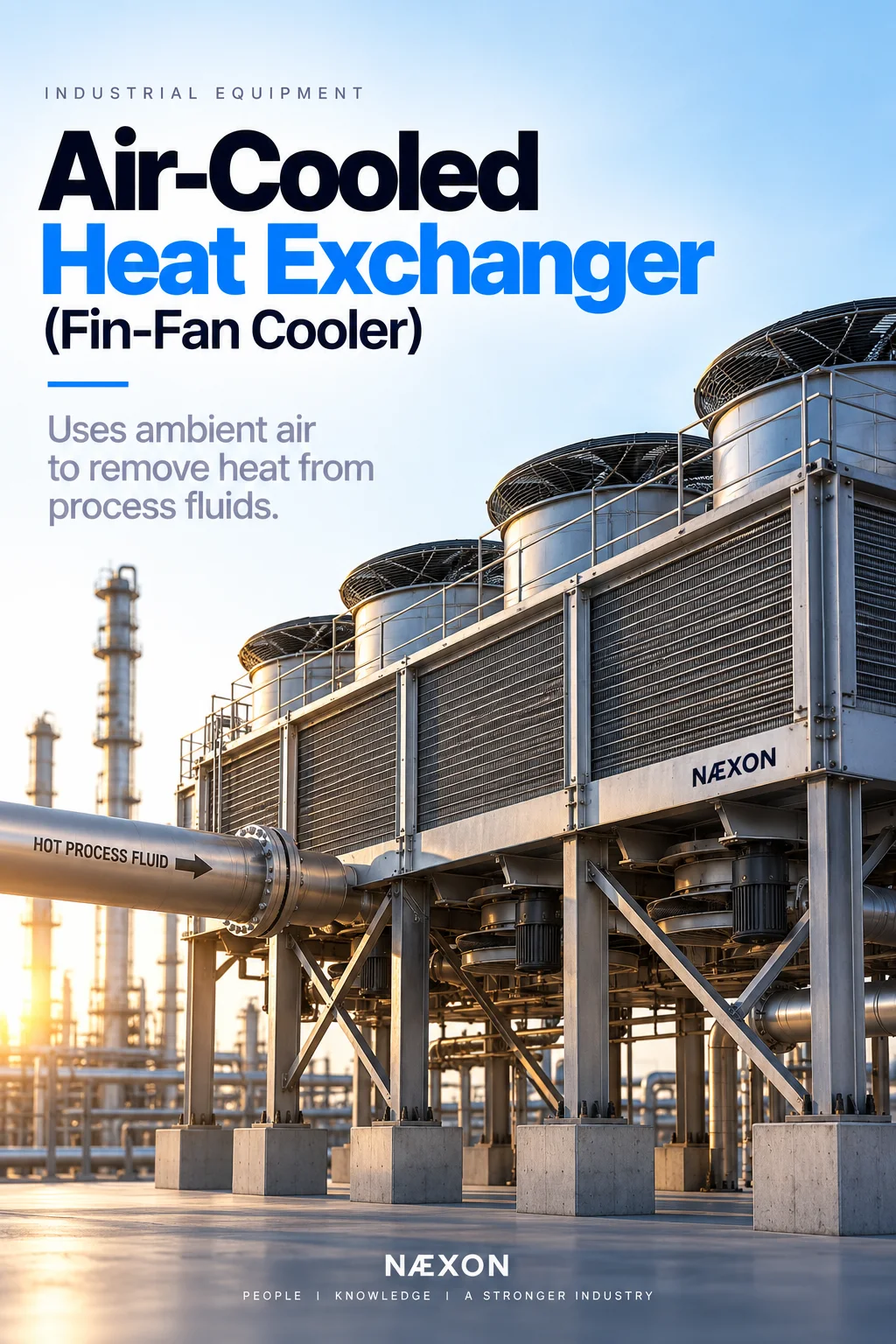
Walk through almost any refinery, petrochemical plant, gas-processing facility, or chemical plant and you will eventually see large rectangular structures elevated above the pipe rack with several enormous fans.
These are air-cooled heat exchangers, commonly called:
- Fin-fans
- Air coolers
- ACHEs — Air-Cooled Heat Exchangers
- Aerial coolers
Their purpose is straightforward:
Use ambient air to remove heat from a process fluid.
Unlike a shell-and-tube exchanger that transfers heat from one process or utility fluid to another, a fin-fan transfers heat directly to the surrounding air.
The basic process is:
Hot Process Fluid → Finned Tubes → Air Removes Heat → Cooled Process Fluid
The concept is simple. The equipment behind it is not.
Fin-fans combine process piping, heat transfer, rotating equipment, structural steel, instrumentation, vibration, electrical equipment, and mechanical systems into one package.
For pipefitters, millwrights, operators, electricians, instrument technicians, welders, inspectors, and refinery maintenance personnel, understanding fin-fans is essential field knowledge.
What Is an Air-Cooled Heat Exchanger?
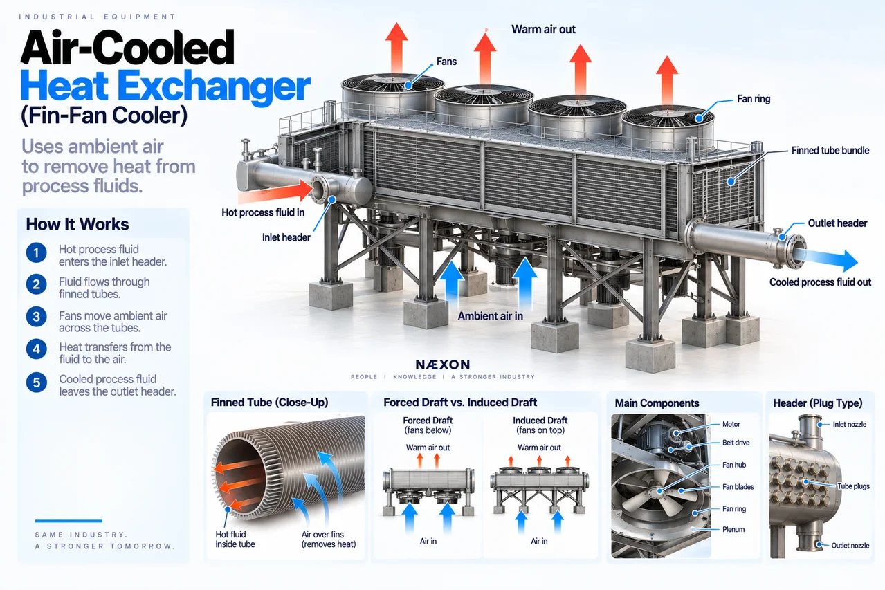
Figure: Air-cooled heat exchanger (fin-fan cooler) showing how hot process fluid flows through finned tubes while fans move ambient air across the bundle to remove heat, along with the major components and forced-draft versus induced-draft configurations.
An air-cooled heat exchanger uses atmospheric air as the cooling medium.
Hot process fluid flows inside tubes.
Air flows across the outside of those tubes.
Heat moves:
Hot Process Fluid → Tube Wall → Fins → Air
The heated air then escapes into the atmosphere.
The process fluid remains contained inside the tubes.
There is normally no direct contact between the process fluid and cooling air.
Why Refineries Use Fin-Fans
Refineries have enormous cooling requirements.
Process streams leave:
- Reactors
- Compressors
- Distillation systems
- Fired heaters
- Separators
- Heat exchangers
at elevated temperatures.
Before those streams can enter downstream equipment, storage, separation systems, or other processing steps, heat often needs to be removed.
Fin-fans provide that cooling without consuming large quantities of cooling water.
This is especially valuable where water availability is limited or where reducing cooling-water demand is desirable.
The Basic Fin-Fan Process
Imagine hot hydrocarbon leaving a reactor system.
It enters the fin-fan through an inlet header.
The process fluid divides among many parallel tubes.
Fans move large quantities of atmospheric air across the tubes.
Heat transfers from the hot fluid through the tube wall and fins into the air.
The cooled process fluid collects in the outlet header and continues downstream.
The sequence is:
Hot Fluid In
↓
Header
↓
Multiple Finned Tubes
↓
Airflow Across Tubes
↓
Outlet Header
↓
Cooled Fluid Out
Meanwhile:
Cool Ambient Air ↑
Heat Transfer
Warm Air ↑
Why the Tubes Have Fins
If you looked closely at a fin-fan tube, you would notice that it does not normally look like ordinary bare pipe.
The outside contains many closely spaced metal fins.
Why?
Because air is relatively poor at transferring heat compared with many liquids.
The solution is to dramatically increase the outside surface area.
A bare tube might expose only its outside cylindrical surface.
Add hundreds of fins and the effective heat-transfer area becomes much larger.
Think:
More surface area = more opportunity to transfer heat to the air.
The Finned Tube
The finned tube is the heart of the exchanger.
Process fluid flows through the inner tube.
Heat travels through:
Process Fluid
↓
Tube Wall
↓
Fin
↓
Air
The fins are thermally connected to the tube so heat can spread outward.
Different fin constructions are used depending on temperature, corrosion conditions, mechanical requirements, and service.
Tube Bundle
A single finned tube cannot handle the enormous heat load of many refinery processes.
Fin-fans therefore contain tube bundles.
A bundle may contain many rows of parallel tubes arranged across a large rectangular area.
The process fluid divides among these tubes.
Air moves through the entire bundle.
Large refinery installations may contain multiple bundles arranged side by side.
From below, the equipment can look enormous.
Headers
At each end of the tube bundle are headers.
The inlet header distributes process fluid into the tubes.
The outlet header collects it again.
Simplified:
Inlet Nozzle → Header → Tubes → Header → Outlet Nozzle
The headers are pressure-containing components.
They may handle:
- Hydrocarbons
- Hydrogen-rich streams
- Gas
- Condensing vapor
- Process liquids
- Other refinery fluids
Header integrity is therefore critical.
Plug Headers
Many air coolers use plug-type headers.
Each tube position can have an access plug installed in the header.
Removing plugs during maintenance can provide access to individual tube ends for inspection or cleaning.
This creates the characteristic appearance of a fin-fan header with rows of threaded plugs.
These plugs are pressure-boundary components.
Correct installation matters.
Why Fin-Fans Are Usually Elevated
Most fin-fans are mounted above grade on structural steel.
There are several reasons.
One major reason is airflow.
The fans need access to large quantities of atmospheric air.
Elevating the equipment also allows:
- Process piping underneath
- Fan access
- Motor access
- Structural support
- Better air circulation
- Integration with pipe racks
Many refinery fin-fans are installed directly above pipe racks.
The Fan
The large rotating fan moves air through the tube bundle.
These fans can be several feet in diameter and move enormous volumes of air.
Unlike a small household fan, industrial fin-fan blades are engineered for:
- High airflow
- Mechanical strength
- Efficiency
- Controlled pitch
- Long operating life
The fan assembly typically includes several blades attached to a central hub.
Fan Blades
Fan blades may be manufactured from materials such as:
- Aluminum
- Fiberglass-reinforced materials
- Other engineered composites
Blade angle—or pitch—influences how much air the fan moves and how much power it requires.
Incorrect blade pitch can affect performance and motor loading.
Blade settings therefore must follow the specified configuration.
Fan Hub
The blades attach to the fan hub.
The hub transfers rotational force from the drive system to the blades.
During maintenance, blade condition and attachment are important.
Potential issues can include:
- Loose hardware
- Cracking
- Blade damage
- Incorrect pitch
- Imbalance
At operating speed, even relatively small imbalance can create significant vibration.
Fan Ring
Around the fan is a circular enclosure called the fan ring.
The fan ring helps direct airflow through the exchanger.
The clearance between blade tips and the fan ring affects efficiency.
Too much clearance allows air to recirculate around the blade tips.
Too little clearance creates the risk of mechanical contact.
Plenum
Between the fan and tube bundle is a large enclosed region called the plenum.
The plenum helps distribute airflow across the exchanger bundle.
Conceptually:
Fan → Plenum → Tube Bundle
or, depending on design:
Tube Bundle → Plenum → Fan
That difference leads us to the two major fin-fan configurations.
Forced-Draft Fin-Fan
In a forced-draft air cooler, the fan is located below the tube bundle.
The fan pushes ambient air upward through the tubes.
The arrangement is:
Ambient Air
↓
Fan
↓
Air Pushed Up
↓
Tube Bundle
↓
Warm Air Leaves
From the ground, the fan is often clearly visible underneath the exchanger.
Advantages of Forced Draft
Forced-draft designs can offer benefits such as easier access to the fan and drive equipment.
The fan and motor also handle relatively cool incoming air rather than the warmer air leaving the exchanger.
However, actual equipment selection depends on many engineering considerations.
Induced-Draft Fin-Fan
In an induced-draft air cooler, the fan is located above the tube bundle.
Instead of pushing air through the bundle, the fan pulls air through it.
The sequence becomes:
Ambient Air
↓
Tube Bundle
↓
Fan
↓
Warm Air Discharged Upward
This creates a different physical appearance.
If the fans are on top:
Induced draft.
If the fans are underneath:
Forced draft.
That is an easy field identification rule.
Why Induced Draft Can Be Useful
Because the fan pulls air through the bundle and discharges it upward, induced-draft arrangements can provide good airflow distribution and help reduce some forms of hot-air recirculation.
However, the fan and mechanical components may operate in warmer discharge air.
Neither arrangement is universally “better.”
The correct design depends on the application.
Fan Drive System
The fan needs a driver.
Most refinery fin-fans use electric motors.
The motor may drive the fan through systems such as:
- Belt drive
- Gear drive
- Direct mechanical arrangements
A typical arrangement might be:
Electric Motor → Belt/Sheaves → Fan Shaft → Fan
or:
Electric Motor → Gearbox → Fan
Belt-Driven Fin-Fans
Some air coolers use belts and sheaves.
The motor rotates a drive sheave.
Belts transfer power to the fan shaft.
Important maintenance concerns include:
- Belt condition
- Belt tension
- Sheave alignment
- Guards
- Bearings
Loose or damaged belts can reduce fan speed and cooling capacity.
Gear-Driven Fin-Fans
Larger systems may use a gearbox.
The motor operates at one speed while the fan requires another.
The gearbox provides the required speed relationship.
Gearboxes introduce additional maintenance considerations such as:
- Lubrication
- Bearings
- Gear condition
- Alignment
- Vibration
- Oil leakage
Louvers
Some fin-fans have louvers installed above or below the tube bundle.
Louvers control how much air passes through the exchanger.
Think of them as large adjustable shutters.
Louvers open → More airflow
Louvers close → Less airflow
They can therefore help regulate cooling.
Variable-Pitch Fans
Some fin-fans control airflow by changing fan blade pitch.
Instead of simply turning the fan on or off, blade angle can be adjusted.
More aggressive blade pitch can move more air.
Reduced pitch moves less air.
Some systems can even move the blades toward a near-neutral position when less cooling is required.
Variable-Speed Drives
Modern systems may use variable-frequency drives or other speed-control methods.
Reducing fan speed reduces airflow.
Increasing fan speed increases airflow.
This provides another way to control outlet temperature while reducing unnecessary energy consumption.
Temperature Control
A fin-fan usually does not need maximum cooling all the time.
Ambient temperature changes throughout:
- Day
- Night
- Summer
- Winter
Process conditions also change.
Control systems may regulate cooling by:
- Starting or stopping fans
- Changing fan speed
- Adjusting blade pitch
- Opening or closing louvers
- Bypassing process flow in appropriate designs
The objective is to maintain the required process outlet temperature.
Ambient Temperature Matters
Fin-fans depend on outside air.
That means their performance is directly affected by weather.
On a cold winter day, cooling can be extremely effective.
On a hot summer afternoon, cooling becomes more difficult.
The same exchanger therefore has different available cooling capability depending on ambient conditions.
This is one of the fundamental differences between an air cooler and many water-cooled exchangers.
Hot-Air Recirculation
A fin-fan is supposed to pull in relatively cool ambient air and discharge warmer air.
But sometimes discharged hot air can circulate back toward the exchanger inlet.
This is called hot-air recirculation.
Instead of receiving cool ambient air, the exchanger receives air it has already heated.
Cooling performance decreases.
Equipment layout and wind conditions can influence this behavior.
Wind Effects
Wind can significantly affect air-cooled exchanger performance.
Depending on direction and speed, wind may:
- Alter airflow distribution
- Promote hot-air recirculation
- Affect fan performance
- Create uneven cooling across bundles
This is one reason refinery fin-fan structures and layouts are carefully engineered.
Winter Operation
Cold weather introduces an entirely different problem:
Too much cooling.
Some process streams can become too cold.
Potential problems may include:
- High viscosity
- Wax formation
- Freezing of water-containing streams
- Hydrate formation in applicable services
- Poor downstream operation
Operators may therefore reduce airflow during cold conditions.
Air Recirculation Systems
Some cold-climate fin-fan installations include systems that recirculate some warm discharge air back toward the inlet.
This may sound backwards.
During summer, hot-air recirculation is undesirable.
During extreme winter conditions, controlled warm-air recirculation can help prevent overcooling or freezing.
The difference is whether the recirculation is intentional and controlled.
Condensing Service
Not every fin-fan simply cools a liquid.
Some are used as condensers.
Hot vapor enters the tubes.
Heat is removed.
The vapor changes phase:
Vapor → Liquid
This phase change can remove large amounts of heat.
Air-cooled condensers are common in many refinery and petrochemical processes.
Two-Phase Flow
During condensing service, both vapor and liquid may exist inside the tubes.
That means flow distribution becomes particularly important.
Poor distribution can cause some tubes to carry more vapor or liquid than others.
Equipment orientation and piping design are therefore important.
Fin Fouling
The fins need clean airflow.
But refinery environments can contain:
- Dust
- Dirt
- Debris
- Process contamination
- Insects
- Vegetation
- Airborne material
These materials can accumulate between fins.
When airflow becomes restricted, heat transfer decreases.
The exchanger may appear mechanically healthy while losing thermal performance because the fin surfaces are dirty.
Bent Fins
Fins are thin and relatively easy to damage.
Bent fins reduce the open area available for airflow.
Large areas of crushed fins can significantly reduce cooling performance.
During maintenance, workers should avoid walking directly on or damaging finned surfaces unless the equipment and procedure specifically provide suitable access.
Tube-Side Fouling
Fouling can also occur inside the tubes.
Deposits create resistance to both flow and heat transfer.
The process becomes:
Hot Fluid → Deposit → Tube Wall → Fin → Air
The additional layer reduces thermal efficiency.
Depending on design and service, tubes may require mechanical or chemical cleaning.
Tube Leaks
A leaking tube releases process fluid into the air cooler structure.
Depending on service, this can be extremely serious.
A leak may involve:
- Flammable hydrocarbons
- Hydrogen
- Toxic material
- Hot process fluid
- High-pressure gas
Because fans continuously move large quantities of air, leakage around fin-fans requires careful response under site procedures.
Why Fin-Fan Leaks Can Be Difficult to Locate
A tube bundle may contain hundreds of tubes.
Finding the exact leaking tube can require inspection and testing.
During maintenance, techniques may include appropriate pressure testing or other approved inspection methods.
Once identified, a damaged tube may be repaired or plugged according to the approved engineering procedure.
Tube Plugging
In some exchanger designs and services, an individual leaking tube may be removed from service by plugging it.
However:
Every plugged tube removes heat-transfer surface.
A few plugged tubes may be acceptable within engineering limits.
Too many can reduce exchanger capacity significantly.
Tube plugging is therefore tracked.
Header Plug Leaks
Plug-header designs introduce another potential leak location.
Each header plug must maintain the pressure boundary.
Problems can involve:
- Damaged threads
- Improper installation
- Gasket or sealing issues
- Corrosion
- Incorrect torque or tightening
- Thermal cycling
Never treat a header plug like an ordinary pipe plug.
Follow the specific equipment procedure.
Vibration
Fin-fans contain large rotating components.
Vibration can originate from:
- Fan imbalance
- Damaged blades
- Loose blades
- Bearing problems
- Misalignment
- Belt problems
- Gearbox problems
- Structural looseness
- Aerodynamic effects
Vibration can damage both rotating equipment and surrounding structures.
Blade Imbalance
Imagine one fan blade accumulating material or becoming damaged.
The fan’s mass is no longer evenly distributed.
At operating speed, that imbalance creates cyclic forces.
The result can be:
Vibration → Bearing Load → Structural Stress → Mechanical Damage
Blade condition therefore matters.
Bearings
Fan shafts and drive systems rely on bearings.
Bearing problems can result from:
- Poor lubrication
- Contamination
- Misalignment
- Excessive vibration
- Normal wear
- Incorrect installation
Operators and maintenance personnel may monitor bearing temperature and vibration.
Fan Guards
Large rotating fan blades can cause catastrophic injury.
Fin-fans therefore use guards and protective structures to prevent personnel from entering rotating equipment.
Never remove or bypass guards while equipment is operating.
Before maintenance, the applicable electrical and mechanical energy sources must be isolated according to site lockout/tagout requirements.
Process Piping Connections
Fin-fan process piping commonly connects to large inlet and outlet headers.
Because the exchanger is elevated, piping may travel upward from the pipe rack to the bundle.
Workers should pay attention to:
- Thermal expansion
- Nozzle loads
- Supports
- Guides
- Spring hangers
- Drainability
- Venting
The exchanger should not be used to pull badly aligned piping into position.
Thermal Expansion
Hot process piping expands.
The fin-fan bundle and supporting steel may also move as temperature changes.
Piping flexibility must accommodate this movement.
Depending on the installation, engineers may use:
- Expansion loops
- Guides
- Sliding supports
- Spring supports
- Flexible routing
The goal is to control loads on exchanger headers and nozzles.
Vents and Drains
Because fin-fans are elevated and contain multiple parallel tubes, proper venting and draining can be important.
High points may trap gas.
Low points may retain liquid.
During shutdown and maintenance, crews must understand how the equipment is safely:
- Isolated
- Depressurized
- Drained
- Vented
- Purged
Never assume a bundle is empty simply because a main line has been drained.
Fin-Fan Banks
Large process services may use several air-cooler bays operating together.
For example:
Bay 1 | Bay 2 | Bay 3 | Bay 4
Each bay may have one or more fans.
Operators can sometimes change the number of operating fans according to cooling demand.
This gives the system flexibility.
What Happens If One Fan Trips?
If one fan stops, the process does not necessarily stop immediately.
The remaining fans and natural airflow may still remove some heat.
But total cooling capacity decreases.
The outlet process temperature may begin to rise.
Depending on service and operating conditions, operators may:
- Start another available fan
- Increase airflow elsewhere
- Reduce process rate
- Adjust upstream conditions
- Follow unit-specific operating procedures
The effect depends on how critical the cooler is.
What Happens If the Entire Fin-Fan Bank Trips?
Losing all fans can be much more significant.
Process temperature downstream may rise.
That can affect:
- Separators
- Compressors
- Distillation equipment
- Storage
- Product quality
- Downstream equipment
A cooling failure can therefore propagate through an entire process unit.
Natural Draft Still Exists
Even with fans stopped, hot tubes can cause some air movement through natural convection.
Hot air rises.
Cooler air enters from below.
However, natural draft normally provides much less cooling than operating fans.
It should not be assumed to provide sufficient process duty.
Fire Considerations
Fin-fans may contain large inventories of pressurized hydrocarbons above operating areas and pipe racks.
A process leak can therefore create a serious fire hazard.
Emergency response may involve:
- Process isolation
- Depressurization
- Equipment shutdown
- Fire protection systems
- Area control
Workers should know the service of the fin-fan they are working around.
What Workers Inspect During a Turnaround
Depending on scope, maintenance and inspection may include:
- Tubes
- Fins
- Headers
- Header plugs
- Welds
- Nozzles
- Fan blades
- Fan hubs
- Fan rings
- Bearings
- Belts
- Sheaves
- Gearboxes
- Motors
- Louvers
- Plenums
- Structural steel
- Guards
- Supports
The exchanger is both process equipment and rotating equipment.
That makes multidisciplinary coordination important.
Cleaning Fin-Fans
Dirty fins reduce airflow and heat transfer.
Cleaning methods depend on the equipment and contamination.
The goal is to remove deposits without damaging the thin fins.
After cleaning, the bundle should provide better airflow and expose more heat-transfer surface.
This can restore cooling performance without changing the process itself.
Fin-Fan vs. Shell-and-Tube Exchanger
Both transfer heat.
But they use different cooling media.
Shell-and-Tube Exchanger
Process Fluid ↔ Another Liquid or Process Fluid
Fin-Fan
Process Fluid ↔ Atmospheric Air
A shell-and-tube exchanger can provide strong heat-transfer performance in a compact package.
A fin-fan avoids or reduces cooling-water use but often requires a much larger physical area.
Fin-Fan vs. Cooling Tower
These are sometimes confused.
A fin-fan directly cools process fluid inside tubes using air.
A cooling tower cools circulating cooling water, which can then be sent to other heat exchangers.
So:
Fin-Fan: Process → Air
Cooling Tower: Cooling Water → Air
The cooling tower will be another equipment topic in this series.
Important Terminology
ACHE — Air-Cooled Heat Exchanger.
Fin-Fan — Common refinery name for an air-cooled exchanger.
Tube Bundle — Group of finned tubes providing heat-transfer surface.
Header — Pressure-containing chamber distributing or collecting process fluid.
Finned Tube — Tube with extended external surface area.
Forced Draft — Fan below the bundle pushing air through it.
Induced Draft — Fan above the bundle pulling air through it.
Plenum — Enclosure directing airflow between fan and bundle.
Fan Ring — Circular structure surrounding the fan.
Blade Pitch — Angle of the fan blade.
Louvers — Adjustable panels controlling airflow.
Hot-Air Recirculation — Warm discharge air returning to the exchanger inlet.
Tube Plugging — Removing a leaking tube from service by sealing its ends where permitted.
What Every Pipefitter Should Recognize
When you approach a fin-fan, do not simply see:
Big fans above the pipe rack.
Identify:
- Hot process inlet
- Inlet header
- Finned tube bundle
- Outlet header
- Cooled process outlet
- Vents
- Drains
- Supports
- Fan arrangement
- Motor and drive system
Then determine:
Which direction is the process flowing?
Which direction is the air flowing?
Is the unit forced draft or induced draft?
Is the process simply cooling or actually condensing?
Those four questions explain most of what the exchanger is doing.
Field Rules
When working around air-cooled heat exchangers:
- Verify process service from approved drawings and equipment identification.
- Treat headers and tubes as pressurized process equipment until isolation is proven.
- Follow approved depressurization, draining, venting, purging, and line-opening procedures.
- Lock out fan motors and all applicable stored-energy sources before entering guarded areas.
- Never rely solely on a stopped fan as proof of isolation.
- Never place tools or materials where they can fall into fan assemblies.
- Protect thin fins from unnecessary mechanical damage.
- Do not change fan blade pitch without the approved procedure.
- Maintain specified fan-tip clearance.
- Verify belt, sheave, gearbox, and coupling guards before returning equipment to service.
- Do not force process piping into header alignment.
- Maintain engineered supports, guides, and spring hangers.
- Treat header plugs as pressure-boundary components.
- Maintain foreign-material exclusion during open-bundle work.
- Verify all tools, temporary materials, and personnel are clear before removing lockout/tagout and starting a fan.
Knowledge Check
- What is the primary purpose of an air-cooled heat exchanger?
- Where does the process fluid normally flow?
- Why are fins installed on the tubes?
- What does the inlet header do?
- What is the difference between forced draft and induced draft?
- What does the plenum do?
- How can blade pitch affect cooling?
- Why does ambient temperature affect fin-fan performance?
- What is hot-air recirculation?
- Why can dirty or bent fins reduce cooling capacity?
- Why must tube plugging be tracked?
- Why is lockout/tagout especially important around fin-fans?
Practical Field Exercise
Find an air-cooled heat exchanger on an approved refinery P&ID and equipment layout.
First trace the process:
Hot Process Inlet → Inlet Header → Tube Bundle → Outlet Header → Cooled Process Outlet
Then inspect the equipment arrangement and determine whether it is:
Forced Draft
or
Induced Draft
Next identify:
- Fan
- Fan blades
- Fan ring
- Plenum
- Motor
- Drive system
- Tube bundle
- Headers
- Vents
- Drains
- Process piping
- Structural supports
Now picture the two flows happening simultaneously:
Process Fluid → Through Tubes
and
Ambient Air → Across Tubes
They never intentionally mix.
Heat simply moves from one to the other.
Final Takeaway
An air-cooled heat exchanger is essentially a massive industrial radiator.
Hot refinery process fluid travels through finned tubes.
Fans move enormous quantities of atmospheric air across those tubes.
Heat moves:
Process Fluid → Tube Wall → Fins → Air
The cooled process stream continues downstream while the heated air returns to the atmosphere.
But understanding a fin-fan means looking beyond the fans.
The headers distribute the process. The tubes contain it. The fins increase heat-transfer area. The fans create airflow. The plenum directs that air. Louvers, fan speed, and blade pitch can control cooling.
And weather becomes part of the process.
The easiest field rule to remember is:
Fans underneath = forced draft.
Fans on top = induced draft.
Once you can identify those components and trace both the process-flow path and the airflow path, a fin-fan stops looking like a giant fan sitting over a pipe rack—and starts making sense as one complete heat-transfer system.


