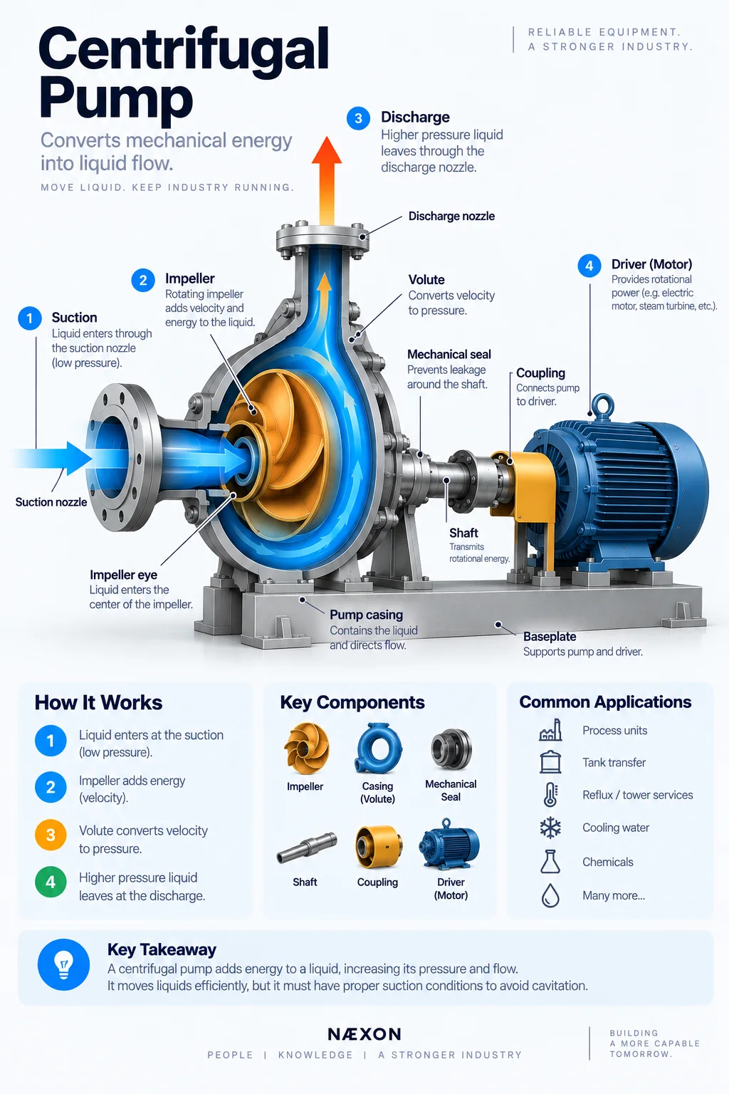
Figure: Cutaway view of a centrifugal pump showing how liquid enters through the suction, flows into the impeller eye, gains energy from the rotating impeller, and exits through the discharge at higher pressure.
Walk through almost any refinery process unit and you will find centrifugal pumps everywhere.
They move crude oil, hydrocarbons, water, condensate, chemicals, cooling water, tower bottoms, reflux, intermediate products, and countless other liquids from one part of the process to another.
A pump may look relatively simple from the outside—a casing connected to piping, coupled to a motor or turbine—but inside, a rapidly rotating impeller is converting mechanical energy into fluid movement.
For pipefitters, millwrights, operators, mechanics, welders, inspectors, and maintenance personnel, centrifugal pumps are fundamental refinery equipment.
What Is a Centrifugal Pump?
A centrifugal pump is a rotating machine designed primarily to move liquid.
The basic energy path is:
Driver → Shaft → Impeller → Liquid velocity → Pressure/flow
An electric motor or other driver rotates a shaft.
The shaft turns an impeller.
Liquid enters near the center of the impeller, gains energy as the impeller rotates, and moves outward into the pump casing.
The casing then helps convert part of that velocity energy into pressure.
The result:
Low-pressure liquid enters the suction.
Higher-energy liquid leaves the discharge.
Why Refineries Need Pumps
Refinery liquids constantly need to move.
Pumps may be used to:
- Transfer liquid between vessels.
- Feed process units.
- Circulate liquid through heat exchangers.
- Return reflux to distillation towers.
- Circulate tower bottoms through reboilers.
- Move finished and intermediate products.
- Transfer tank contents.
- Provide cooling-water circulation.
- Increase liquid pressure for downstream equipment.
- Circulate chemicals and utility fluids.
Without pumps, most refinery liquid systems would stop moving.
The Basic Flow Path
The easiest way to understand a centrifugal pump is to follow the liquid.
Suction piping
↓
Pump suction nozzle
↓
Impeller eye
↓
Impeller
↓
Volute / diffuser
↓
Discharge nozzle
↓
Discharge piping
The pump does not simply “push” liquid from the suction pipe into the discharge pipe.
It adds energy to the liquid.
1. Suction Nozzle
Liquid first enters through the suction nozzle.
This piping deserves special attention because centrifugal pumps require good suction conditions.
Poor suction piping can cause serious operating problems even when the pump itself is mechanically perfect.
The suction system should deliver liquid to the impeller with sufficient pressure and stable flow.
2. The Impeller Eye
After entering the casing, liquid approaches the center of the impeller.
This region is called the impeller eye.
The eye is where liquid enters the rotating impeller.
Pressure conditions here are extremely important because this is one of the locations where pressure can become low enough for vapor bubbles to form.
That leads directly to one of the most important pump problems:
cavitation.
3. The Impeller
The impeller is the rotating component that transfers energy into the liquid.
It contains vanes designed to guide the fluid.
As the impeller rotates, liquid entering near its center is accelerated outward.
The fluid gains velocity and energy.
Impellers come in many designs depending on:
- Flow requirement
- Pressure/head requirement
- Fluid properties
- Solids content
- Pump service
- Efficiency requirements
The impeller is the heart of the centrifugal pump.
4. Volute
Around the impeller is the volute in many common pump designs.
The volute is a gradually expanding passage formed into the casing.
High-velocity liquid leaving the impeller enters this passage.
As the flow area increases, velocity decreases and part of the velocity energy is converted into pressure.
This is a critical concept:
The impeller adds energy.
The casing helps convert that energy into useful pressure and flow.
5. Diffusers
Some centrifugal pumps use diffusers rather than relying solely on a volute.
Diffuser vanes surround the impeller and help convert velocity into pressure in a controlled manner.
You will commonly encounter diffuser arrangements in multistage and other engineered pump designs.
6. Pump Casing
The casing forms the primary pressure boundary around the impeller.
It contains the liquid and directs it toward the discharge.
Depending on pump design, the casing may be:
- Radially split
- Axially split
- Single-volute
- Double-volute
- Multistage
The exact design depends on the service.
7. Shaft
The pump shaft connects the rotating assembly to the driver.
Its job is to transmit torque to the impeller.
The shaft passes through areas where rotating components must interface with stationary components.
That creates an obvious engineering challenge:
How do you allow a shaft to rotate through a pressure-containing casing without process liquid leaking everywhere?
That is where the sealing system becomes critical.
8. Mechanical Seal
Modern refinery centrifugal pumps commonly use mechanical seals.
The seal controls leakage where the rotating shaft enters or exits the pressure boundary.
Mechanical seals contain precisely engineered sealing faces operating extremely close together.
Depending on the service, the seal system can also include:
- Seal flush piping
- Barrier fluid
- Buffer fluid
- Seal pots
- Coolers
- Pressure instrumentation
- Temperature instrumentation
- Flow controls
On hazardous hydrocarbon service, seal reliability is particularly important.
A seal leak can release flammable or toxic process material.
9. Bearings
The rotating shaft must remain accurately positioned.
Bearings support the shaft and control radial and axial movement.
Pump bearings may rely on grease or oil lubrication depending on design.
Poor bearing condition can produce:
- Vibration
- Heat
- Noise
- Shaft movement
- Seal damage
- Coupling problems
- Eventually mechanical failure
A pump is a precision rotating machine.
Small alignment problems can become significant at operating speed.
10. Coupling
The pump shaft normally connects to the driver through a coupling.
The coupling transmits torque while accommodating limited movement depending on its design.
It is not intended to compensate for major misalignment.
Proper pump-to-driver alignment remains essential.
11. Driver
The pump needs an external source of mechanical energy.
The most common driver is an electric motor.
Refineries may also use:
- Steam turbines
- Engines
- Other specialized drivers
The driver rotates the shaft, which rotates the impeller.
Suction vs. Discharge
Every refinery worker should immediately recognize these two sides of a pump.
Suction
Liquid traveling into the pump.
Discharge
Liquid traveling out of the pump after energy has been added.
Discharge pressure is normally higher than suction pressure while the pump is operating.
But pipe size alone does not reliably tell you which side is which.
Always verify the system using drawings and line identification.
Why Suction Piping Is So Important
Centrifugal pumps do not perform well when their suction conditions are poor.
Problems can result from:
- Excessive suction pressure loss
- Restricted strainers
- Closed or partially closed valves
- Vapor entering the suction
- Poor piping configuration
- Insufficient liquid level
- Excessive liquid temperature
- Air entering the system
- Improper reducer orientation
- Fouling or plugging
A pump problem can therefore originate several feet—or hundreds of feet—upstream of the pump.
What Is Cavitation?
Cavitation is one of the most important centrifugal-pump problems to understand.
If local pressure in the liquid falls below its vapor pressure, small vapor bubbles can form.
As those bubbles travel into higher-pressure regions inside the pump, they collapse.
That collapse can be extremely violent on a microscopic scale.
Repeated bubble collapse near metal surfaces can damage the impeller.
What Cavitation May Sound Like
Severe cavitation is often described as sounding like:
gravel or rocks moving through the pump.
Other potential symptoms can include:
- Vibration
- Noise
- Reduced flow
- Reduced head
- Unstable performance
- Impeller damage
Never diagnose solely by sound, but the characteristic noise is worth recognizing.
NPSH: A Term Every Refinery Worker Should Recognize
Pump engineers frequently discuss NPSH, or Net Positive Suction Head.
You do not need to perform pump-design calculations to understand the basic concept.
The pump needs enough pressure at its suction to keep the liquid from vaporizing where pressure drops near the impeller inlet.
Two terms commonly appear:
NPSH Available (NPSHa) — what the actual piping system provides.
NPSH Required (NPSHr) — the pump’s tested requirement at specified operating conditions, as defined by the applicable convention.
The system must provide adequate margin over the pump requirement according to the design criteria.
Conceptually:
Not enough suction pressure margin → greater cavitation risk.
Why Hot Liquid Can Be Difficult to Pump
As liquid temperature rises, its vapor pressure generally rises.
That means a hot liquid may begin vaporizing at a higher absolute pressure than the same liquid when cold.
This matters tremendously in refinery service.
Hot tower-bottom pumps and other high-temperature hydrocarbon pumps may require carefully designed suction systems.
The vessel elevation, liquid level, piping pressure drop, and fluid temperature all matter.
Why Pumps Are Sometimes Below Vessels
You may notice refinery pumps installed substantially below the vessels supplying them.
That elevation difference can provide additional static liquid head at the pump suction.
In simple terms:
More liquid above the pump can provide more suction pressure.
This can be particularly important for hot or volatile liquids.
Equipment elevation in a refinery is often driven by process requirements—not architectural convenience.
Suction Reducers
Pipefitters frequently encounter reducers immediately before horizontal pump suction nozzles.
An eccentric reducer is commonly used in many horizontal suction configurations where the design requires avoiding a high-point vapor pocket.
But this should never become a blindly applied rule.
Reducer orientation depends on the specific piping arrangement and engineering requirements.
Install it exactly as shown on the approved drawing.
Pump Discharge
After leaving the casing, the higher-energy liquid enters the discharge piping.
Discharge systems commonly contain equipment such as:
- Check valve
- Isolation valve
- Pressure instrumentation
- Flow instrumentation
- Minimum-flow system
- Downstream process equipment
The exact arrangement depends on the service.
Why a Check Valve Is Used
A discharge check valve can prevent reverse flow when the pump stops.
Without appropriate protection, downstream pressure could potentially drive liquid backward through the pump.
Reverse flow can create mechanical and process problems.
The check valve automatically responds to flow direction rather than requiring an operator to manually close it every time the pump stops.
Minimum Flow
A centrifugal pump generally should not operate indefinitely at extremely low flow.
At low flow, much of the energy being added by the pump can become heat and internal recirculation rather than useful process flow.
This can contribute to:
- Temperature rise
- Vibration
- Internal recirculation
- Seal problems
- Mechanical damage
Some critical pumps therefore use a minimum-flow recycle.
A portion of discharge flow is routed back upstream or to another suitable destination to maintain adequate flow through the pump.
Deadheading
Deadheading occurs when a centrifugal pump operates against a closed or severely restricted discharge with little or no flow.
The impeller continues adding energy.
But the liquid has nowhere useful to go.
Energy can become heat.
Temperature can rise.
The pump can be damaged.
This is one reason operating procedures and minimum-flow protection matter.
Pump Curve
A centrifugal pump’s performance changes with flow.
Manufacturers characterize pumps using a pump curve.
A typical curve can show relationships between:
- Flow
- Head
- Efficiency
- Power
- NPSH requirement
The pump does not simply produce one fixed discharge pressure regardless of system conditions.
Its operating point is determined by the interaction between the pump and the piping system.
Best Efficiency Point
The Best Efficiency Point, or BEP, is the region where a centrifugal pump operates most efficiently for its design.
Operating far away from BEP can increase undesirable hydraulic forces, recirculation, vibration, and wear.
A pump may still move liquid away from BEP.
That does not mean it is operating under ideal conditions.
Series vs. Parallel Pumps
Pumps can be arranged in different ways.
Parallel
Two pumps discharge into a common system.
This arrangement can increase available flow and may provide operating flexibility.
Series
The discharge of one pumping stage feeds another.
This can increase total head.
Actual refinery arrangements depend on the process requirements.
Main Pump and Spare Pump
A very common refinery arrangement is:
Pump A + Pump B
One operates.
The other remains available as a spare or standby.
This allows maintenance or failure of one pump without necessarily stopping the entire process.
That is why you frequently see nearly identical pumps sitting beside each other.
Pump Alignment
The pump and driver shafts need to be properly aligned.
Misalignment can contribute to:
- Coupling wear
- Bearing damage
- Seal problems
- Vibration
- Shaft stress
Alignment may change as piping is connected or equipment heats up.
This is one reason pipefitters and millwrights must coordinate closely around rotating equipment.
Pipe Strain
Connected piping should not force the pump into alignment.
Excessive piping loads can distort the casing or move the pump from its intended position.
A flange that requires excessive force to line up is not automatically acceptable because the bolts can reach.
The piping and equipment must satisfy the project’s alignment and allowable-load requirements.
Bolts are not alignment tools.
Soft Foot
A motor or pump foot that does not sit properly on its mounting surface can contribute to distortion when hold-down bolts are tightened.
This condition is commonly called soft foot.
Correcting foundation, baseplate, grouting, mounting, and alignment issues is part of establishing a healthy rotating-equipment installation.
Pump Foundations and Baseplates
Pump and driver assemblies are commonly mounted on engineered baseplates and foundations.
These structures help:
- Maintain alignment
- Support equipment weight
- Resist operating loads
- Control vibration
- Provide a stable mounting surface
Poor foundation or grout condition can contribute to recurring equipment problems.
Mechanical Seal Leaks
Mechanical seals are common sources of pump maintenance work.
Seal problems can be associated with:
- Dry running
- Cavitation
- Excessive vibration
- Misalignment
- Contaminated seal fluid
- Incorrect seal-system operation
- Excessive temperature
- Bearing problems
- Shaft movement
Replacing the seal without correcting the underlying problem can lead to another failure.
Bearing Failure
Bearing damage can result from many causes, including:
- Lubrication problems
- Contamination
- Misalignment
- Excessive vibration
- Incorrect installation
- Excessive loads
- Temperature problems
Operators may detect changes in vibration or bearing temperature before catastrophic failure occurs.
Condition monitoring is therefore extremely valuable.
Why Vibration Matters
All rotating machinery vibrates to some degree.
The question is whether that vibration is within acceptable limits and whether it is changing.
Increasing or abnormal vibration can indicate problems involving:
- Bearings
- Alignment
- Cavitation
- Imbalance
- Couplings
- Foundations
- Hydraulic instability
- Mechanical looseness
Vibration analysis can help specialists distinguish among different failure mechanisms.
Pump Startup: Why Priming Matters
Most conventional centrifugal pumps require their casing and suction path to contain liquid before normal pumping begins.
A pump filled primarily with vapor may not develop the intended pumping action.
This is commonly discussed as priming.
Startup procedures vary considerably by system and must follow site instructions.
The field concept is simple:
Centrifugal pumps are designed primarily to move liquid—not pockets of gas.
Common Pump Problems
Workers may encounter:
- Cavitation
- Loss of prime
- Low flow
- Low discharge pressure
- Excessive vibration
- Bearing overheating
- Mechanical seal leakage
- Coupling problems
- Misalignment
- Fouled suction strainers
- Plugged suction piping
- Impeller damage
- Internal wear
- Minimum-flow problems
- Pipe strain
- Foundation or grout deterioration
The visible symptom at the pump may originate somewhere else in the system.
What Workers Inspect During a Turnaround
Depending on the maintenance scope, a pump may be opened and inspected for:
- Impeller condition
- Casing wear
- Shaft condition
- Bearings
- Mechanical seals
- Wear rings
- Sleeves
- Coupling
- Gaskets
- Internal corrosion
- Erosion
- Cavitation damage
- Clearances
Clearances inside rotating equipment can be extremely precise.
This is not equipment where “close enough” is automatically acceptable.
Cavitation Damage
When a cavitating pump is opened, the impeller may show characteristic surface damage.
Repeated vapor-bubble collapse can pit and erode metal surfaces.
Severe damage may resemble a rough, eaten-away surface.
Replacing the impeller without understanding why cavitation occurred may only repeat the problem.
The suction system must also be evaluated.
Important Terminology
Centrifugal Pump — Rotating machine that adds energy to a liquid.
Impeller — Rotating component transferring energy into the liquid.
Impeller Eye — Region where liquid enters the impeller.
Volute — Casing passage helping convert velocity into pressure.
Suction — Pump inlet side.
Discharge — Pump outlet side.
Mechanical Seal — Device controlling leakage around the rotating shaft.
Bearing — Component supporting and positioning the shaft.
Coupling — Connection transmitting torque from the driver to the pump.
Cavitation — Formation and collapse of vapor bubbles due to local pressure conditions.
NPSH — Concept describing suction-pressure margin relative to vaporization and pump requirements.
BEP — Best Efficiency Point.
Deadhead — Operation with little or no discharge flow against a closed/restricted system.
Minimum Flow — Minimum required flow used to protect a pump from damaging low-flow operation.
What Every Pipefitter Should Know
When you walk up to a refinery pump, develop the habit of identifying:
- Suction line
- Discharge line
- Suction reducer
- Check valve
- Isolation valves
- Minimum-flow line
- Seal piping
- Pump casing
- Driver
- Coupling
- Baseplate
- Supports
Then ask:
Where is the liquid coming from?
Where is it going?
Why does it need the pump?
What pressure and temperature is it operating at?
How can the connected piping move without loading the pump?
Those questions turn a pump from an isolated piece of machinery into part of the process.
Field Rules
When working around centrifugal pumps:
- Verify suction and discharge service using approved drawings.
- Never assume flow direction solely from pipe size or equipment appearance.
- Follow isolation, lockout/tagout, draining, depressurization, and line-opening requirements.
- Never use pump flange bolts to force piping into alignment.
- Protect pump nozzles from excessive piping loads.
- Keep open suction and discharge connections clean.
- Protect mechanical-seal systems and small-bore piping from damage.
- Maintain required piping supports and engineered flexibility.
- Never operate or rotate equipment unless authorized by the applicable procedure.
- Treat abnormal vibration, noise, seal leakage, temperature, or cavitation-like conditions according to site procedures.
- Coordinate piping work with rotating-equipment personnel when alignment can be affected.
- Verify final alignment requirements after piping work as required by the project or site procedure.
Knowledge Check
- What does a centrifugal pump add to a liquid?
- Where does liquid enter the impeller?
- What does the impeller do?
- What does the volute do?
- Why is suction piping especially important?
- What is cavitation?
- Why can hot liquids be more difficult to pump?
- What does NPSH relate to?
- Why might a pump have a minimum-flow recycle?
- What is deadheading?
- Why should piping never be forced onto a pump nozzle with flange bolts?
- What is BEP?
Practical Field Exercise
Find a centrifugal pump on an approved refinery P&ID.
Start at the pump suction and trace the entire system.
Identify:
- Source vessel or equipment
- Suction piping
- Suction isolation
- Pump
- Discharge check valve
- Discharge isolation
- Minimum-flow system, if provided
- Destination equipment
Then draw a simple cutaway pump.
Show:
Suction → Impeller Eye → Impeller → Volute → Discharge
Finally, ask one question:
What would happen to this pump if the suction source stopped supplying enough liquid?
If your answer immediately leads you toward loss of suction pressure, vapor formation, cavitation, loss of performance, and possible equipment damage, you are beginning to understand the pump as a complete system.
Final Takeaway
A centrifugal pump converts mechanical rotation into liquid energy.
The driver rotates the shaft.
The shaft rotates the impeller.
Liquid enters through the suction and reaches the impeller eye.
The impeller accelerates the liquid outward.
The casing converts part of that velocity into pressure.
The liquid then leaves through the discharge and continues through the refinery process.
But the pump cannot be understood by looking at the casing alone.
Suction conditions, NPSH, piping alignment, seals, bearings, minimum flow, thermal movement, foundations, and the downstream system all matter.
That is the field lesson worth remembering:
A pump does not operate by itself. It operates as part of a system.


