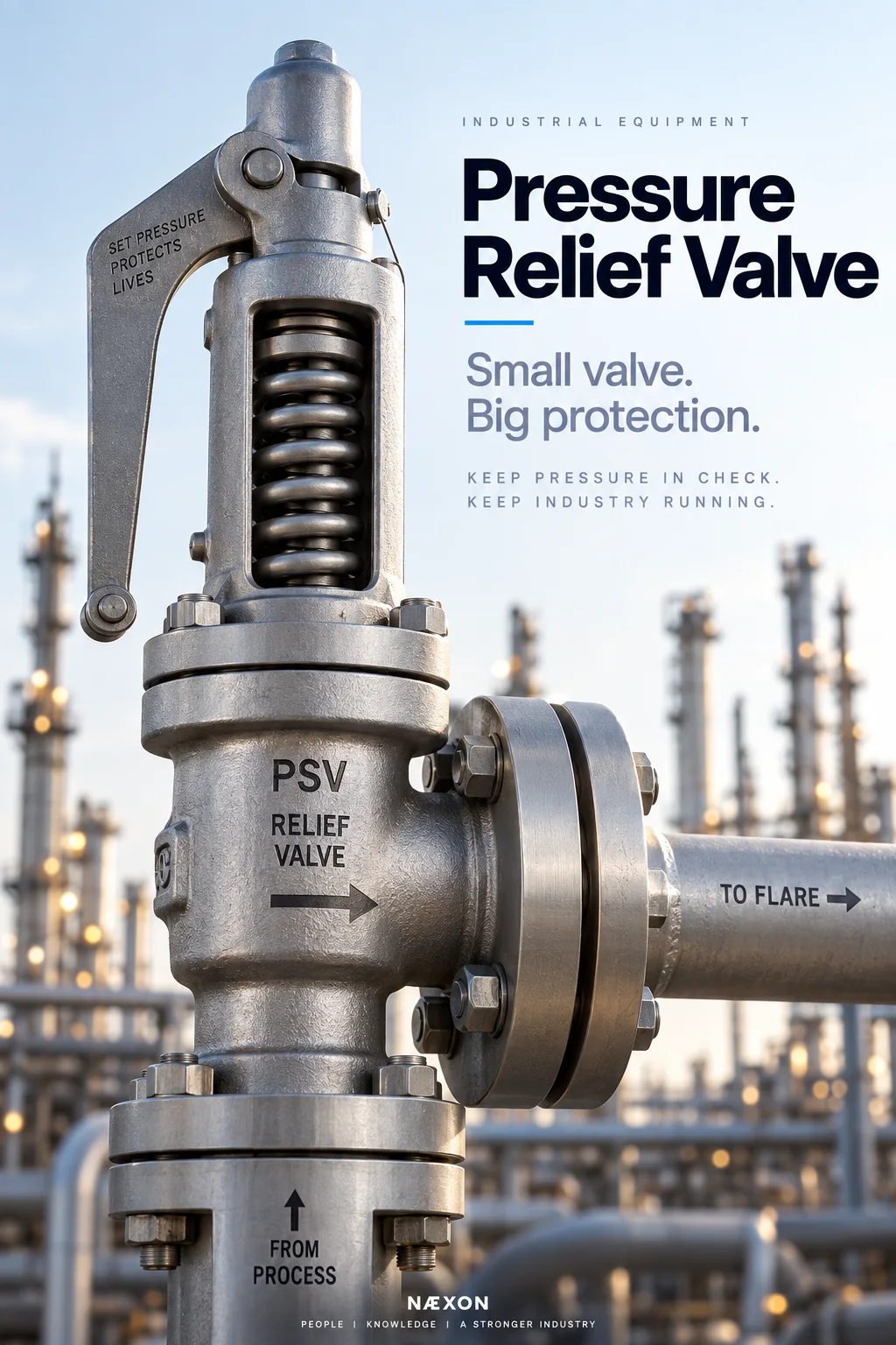
A pressure relief valve, commonly called a PRV, PSV, or simply a relief valve, may be relatively small compared with a distillation tower, compressor, or heat exchanger—but it can protect equipment worth millions of dollars and, more importantly, help prevent a dangerous overpressure event.
Refineries contain pressurized vessels, exchangers, reactors, piping systems, pumps, compressors, boilers, and storage equipment. Under abnormal conditions, pressure can rise beyond what equipment is designed to withstand.
A pressure relief valve provides an engineered escape path.
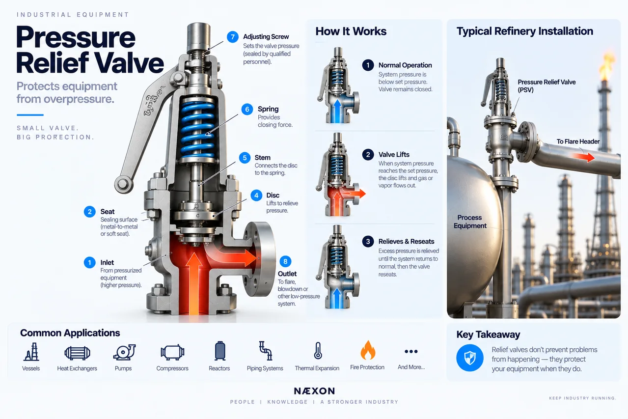
Figure: Pressure relief valve (PSV) cutaway showing its major internal components, operating sequence, and typical refinery installation where excess pressure is safely routed from protected process equipment to the flare system.
The basic principle is:
Normal pressure → Valve closed
Pressure reaches the relieving threshold → Valve opens
Excess pressure is relieved → Protected equipment stays within its pressure-protection basis
For refinery workers, understanding these valves is fundamental field knowledge.
What Is a Pressure Relief Valve?
A pressure relief valve is an automatic pressure-protection device.
It does not normally require an operator to open it.
It does not normally depend on someone noticing high pressure and turning a handwheel.
Instead, the valve responds to pressure according to its design.
Its job is simple:
Protect a pressure-containing system from excessive pressure.
A typical arrangement might be:
Process Vessel → Relief Valve → Flare Header
When abnormal pressure reaches the valve’s set pressure, the valve begins its designed opening action and allows material to leave the protected system.
In many hydrocarbon services, that material is routed into the refinery flare system rather than released directly near personnel.
Why Can Refinery Equipment Overpressure?
Overpressure can develop for many reasons.
Potential scenarios include:
- Blocked outlet
- Control-valve failure
- Loss of cooling
- External fire exposure
- Excessive heat input
- Chemical reaction
- Gas breakthrough
- Thermal expansion of blocked-in liquid
- Compressor-related pressure
- Utility failure
- Tube rupture between systems at different pressures
- Operating error
Relief-system design evaluates credible scenarios and determines the required relieving capacity.
The relief valve is therefore part of a larger engineered protection system.
1. Valve Body
The body is the pressure-containing shell of the relief valve.
It connects the protected equipment to the relief discharge system.
A typical valve has:
Inlet
↓
Seat and Disc
↓
Outlet
The inlet is exposed to pressure from the protected system.
The outlet leads toward the designated relief destination.
2. Nozzle and Seat
Inside the valve is a precisely machined seating area.
During normal operation, the valve disc seals against this surface.
This prevents process fluid from escaping into the relief system.
Seat condition is extremely important.
Damage, deposits, corrosion, or foreign material can prevent proper sealing and cause leakage.
3. Disc
The disc is the movable component that seals against the seat.
Process pressure acts on the disc.
As pressure increases, the upward force acting on the disc increases.
Opposing that force is the valve’s closing force.
In a conventional spring-loaded valve, that closing force comes primarily from a spring.
4. Spring
The spring is one of the defining components of a conventional spring-loaded relief valve.
The spring pushes the disc toward the seat.
During normal operation:
Spring force keeps valve closed.
As system pressure rises:
Pressure force pushes upward against the disc.
When the valve reaches its designed relieving condition, the opening forces overcome the closing forces according to the valve design.
The valve opens.
5. Set Pressure
The set pressure is the inlet pressure at which the relief valve is adjusted to begin its specified opening action under defined service conditions.
This value is not chosen by field personnel.
It is determined as part of the pressure-protection design.
The valve’s identification and documentation provide critical information about its service and settings.
Never casually adjust a relief valve.
What Happens When a Relief Valve Lifts?
Imagine a vessel operating normally.
Pressure is below the relief valve’s set pressure.
The disc remains seated.
Now an abnormal condition develops.
Pressure rises.
The force acting against the disc increases.
Eventually the valve reaches its opening condition.
The disc lifts from the seat.
Process fluid flows through the valve.
Pressure is relieved through the discharge system.
In hydrocarbon service, the path may be:
Vessel → PSV → Relief Header → Flare System
Once the abnormal condition subsides and pressure falls sufficiently, a reclosing valve is designed to reseat.
Pop Action
Many gas- and vapor-service safety valves are designed to open rapidly once the appropriate opening condition is reached.
Workers often refer to this as the valve popping or lifting.
The valve does not necessarily behave like a normal control valve slowly throttling from 0% to 100%.
Its internal geometry is designed to provide the required relieving behavior.
Blowdown
A relief valve does not necessarily close at exactly the same pressure at which it opened.
The difference between the set pressure and the pressure at which the valve reseats is associated with blowdown.
This helps avoid unstable repeated opening and closing around the set point.
That rapid cycling behavior is undesirable.
Chattering
Chattering is rapid opening and closing of a relief valve.
It can be damaging.
Potential consequences include:
- Seat damage
- Disc damage
- Mechanical wear
- Leakage
- Vibration
- Reduced reliability
Chattering can involve problems with relief-system sizing, pressure losses, valve selection, operating conditions, or other system interactions.
A relief valve must be considered as part of the entire inlet and outlet piping system.
Conventional Spring-Loaded PSV
The most familiar design is the conventional spring-loaded pressure safety valve.
Its major components can include:
- Body
- Inlet nozzle
- Seat
- Disc
- Stem
- Spring
- Spring washers
- Adjusting screw
- Bonnet
- Outlet
The process pressure acts beneath the disc while the spring provides closing force.
Simple concept.
Highly engineered execution.
Balanced-Bellows Relief Valve
A balanced-bellows PSV adds a bellows assembly.
One reason for this design is to reduce the effect that variable backpressure can have on valve performance.
The bellows may also help isolate certain internal components from process fluid, depending on design.
These valves are common enough that refinery workers should recognize the term.
Pilot-Operated Relief Valve
Not every relief valve relies primarily on a large mechanical spring.
A pilot-operated pressure relief valve uses system pressure and a pilot control mechanism to control the main valve.
These valves can offer advantages in certain high-pressure or specialized services.
They also introduce additional small-bore sensing and pilot components that must be maintained correctly.
PSV vs. PRV
Workers often hear several abbreviations:
PSV — Pressure Safety Valve
PRV — Pressure Relief Valve
SRV — Safety Relief Valve
Terminology varies with service, company practice, code terminology, and valve type.
In everyday refinery conversation, workers may use some of these terms loosely.
The important field practice is to identify the exact device from the approved documentation and equipment tag.
Where Does the Relieved Material Go?
This is critical.
Opening the valve is only half of the relief system.
The material must also have somewhere safe to go.
Depending on the service, discharge may be routed to:
- Flare header
- Closed relief system
- Blowdown system
- Scrubber
- Recovery system
- Other engineered destination
- Atmosphere, where specifically permitted and designed
For many hydrocarbon services, the flare system is a major destination.
The Flare Connection
Imagine a refinery vessel experiencing an overpressure condition.
The relief valve opens.
Hydrocarbon vapor enters the relief header.
Multiple relief headers may combine into larger flare piping.
The material eventually reaches flare-system equipment and ultimately the flare stack, where combustible material can be safely handled according to the system design.
So the complete protection path can be much larger than the valve:
Equipment → PSV → Branch Relief Line → Header → Flare System
The valve is only one component.
Why Relief Piping Can Be Huge
During a major upset, multiple devices may potentially relieve into a common system according to the scenarios considered in design.
Large quantities of vapor may need to be transported with controlled pressure drop.
This is why refinery flare headers can become extremely large-diameter piping systems.
They are emergency process highways.
Most of the time they may carry relatively little flow.
During an upset, their role becomes critical.
Inlet Piping Matters
The piping between protected equipment and the relief valve is extremely important.
Excessive pressure loss in the inlet piping can interfere with relief-valve performance.
That is why PSV inlet piping is carefully engineered.
Field modifications that appear insignificant can affect the pressure-protection system.
Never alter relief-valve piping without approved engineering.
Outlet Piping Matters Too
The discharge piping can create backpressure at the relief valve outlet.
Backpressure can influence valve performance depending on valve design.
Factors can include:
- Pipe length
- Pipe diameter
- Fittings
- Header pressure
- Simultaneous relief loads
- Fluid properties
This is one reason balanced-bellows and pilot-operated designs may be selected for certain applications.
Isolation Valves Around PSVs
Some installations contain isolation valves associated with relief devices.
This demands strict procedural control.
A relief device that is accidentally isolated may no longer protect the equipment it was intended to protect.
Sites therefore use engineered arrangements and administrative controls appropriate to their systems.
Never change the position of a relief-system isolation valve unless authorized under the applicable procedure.
Thermal Relief Valves
Not every relief valve protects a giant vessel from a dramatic process upset.
Small thermal relief valves protect blocked-in liquid systems.
Imagine liquid trapped between two closed valves.
The pipe is full.
Now the sun or another heat source warms the liquid.
Liquids do not compress easily.
Thermal expansion can create surprisingly high pressure in the blocked section.
A small thermal relief valve can protect that trapped volume.
This is an important field lesson:
A short blocked-in liquid line can still require overpressure protection.
External Fire Scenario
Imagine a pressure vessel exposed to a major external fire.
Heat enters the vessel.
Liquid may boil.
Vapor generation increases.
Pressure rises.
The relief system may be designed to handle the applicable fire case.
This is one reason relief valves on refinery vessels can be much larger than workers might expect from normal operating flow.
They are designed around abnormal scenarios—not ordinary production alone.
Heat Exchanger Tube Rupture Scenario
Consider a heat exchanger with:
High-pressure fluid on one side
and
Lower-pressure equipment on the other side.
If a tube ruptures, high-pressure material may enter the lower-pressure side.
That system could potentially overpressure.
Pressure-protection design considers applicable credible scenarios such as this.
This connects the equipment we have already studied:
Heat Exchanger → Tube Failure → Pressure Imbalance → Relief System Response
Refinery equipment does not operate independently.
Compressor Discharge Protection
Compressors can generate significant discharge pressure.
Downstream equipment must be protected against credible overpressure scenarios.
Relief devices may therefore be part of compressor systems.
Again, the compressor, piping, vessels, controls, shutdown systems, and relief devices work together as layers of protection.
Why Relief Valves Sometimes Leak
A relief valve can begin passing process fluid without experiencing a full relieving event.
Possible contributors can include:
- Damaged seating surfaces
- Deposits
- Corrosion
- Foreign material
- Operation too close to the valve’s intended pressure limits
- Previous lifting
- Mechanical problems
A leaking relief valve should not simply be treated as an annoying small leak.
Its condition affects a safety-critical protection layer.
Why Workers Should Never Hammer on a PSV
A sticking or leaking valve is not repaired by hitting it.
Pressure relief valves are calibrated safety devices.
Improvised field actions can:
- Damage internal components
- Alter seating
- Affect calibration
- Create leakage
- Trigger an unintended release
- Compromise the protective function
Follow the site’s approved response.
Relief Valve Removal
During turnarounds, relief valves are commonly removed for inspection, testing, repair, or certification.
Good field control is essential.
Before removing a valve, crews should follow the approved work package and isolation procedure.
Important identification can include:
- Equipment tag
- Valve tag
- Inlet location
- Outlet location
- Orientation
- Flange rating
- Gasket requirements
- Stud requirements
Relief valves that look nearly identical may have completely different set pressures and services.
Never assume they are interchangeable.
Bench Testing
Relief valves are commonly tested in controlled shop conditions.
Testing can verify parameters required by the applicable procedure and valve type.
Repairs or adjustments are performed by qualified personnel.
Once completed, the valve may be sealed or otherwise controlled to indicate that unauthorized adjustment should not occur.
For field workers, the key principle is:
Calibration belongs to qualified valve technicians—not casual field adjustment.
Why Valve Tags Matter
A relief valve tag may connect the physical device to records containing information such as:
- Protected equipment
- Set pressure
- Service
- Valve size
- Manufacturer
- Model
- Orifice
- Materials
- Inspection history
Installing the wrong relief valve can compromise equipment protection even if the flanges physically fit.
Fit-up does not prove correctness.
Relief Valve Inlet vs. Outlet
A relief valve has a specific flow direction.
Typically:
Protected Equipment → PSV Inlet → PSV Outlet → Relief System
The inlet and outlet may use different flange sizes.
Many PSV designs have an outlet larger than the inlet.
This helps accommodate the expanded relieving fluid and discharge requirements.
But always identify orientation from the valve and approved documentation.
Reaction Forces
When large quantities of high-pressure vapor suddenly move through relief piping, significant forces can develop.
Relief piping may require engineered:
- Supports
- Guides
- Anchors
- Bracing
Do not remove, relocate, or modify these supports because they “look unnecessary.”
They may exist specifically for emergency relieving loads.
Condensation and Drainage
Some relief systems can accumulate condensate.
Poor drainage can create problems such as:
- Liquid pockets
- Corrosion
- Additional backpressure
- Hydraulic loads
- Potential slugging
Relief headers and flare systems therefore often include carefully designed slopes, knockout equipment, and drainage arrangements.
This is one reason piping slope can be especially important in flare systems.
Common Problems Found During Maintenance
Inspection may reveal:
- Corroded bodies
- Damaged seats
- Deposits
- Spring problems
- Bellows damage
- Plugged sensing lines
- Gasket leakage
- Flange damage
- Incorrect valve installation
- Incorrect orientation
- Damaged discharge piping
- Missing or altered supports
- Wrong valve identification
Because the valve may sit quietly for years, inspection and testing are important.
The device must work correctly when finally demanded.
Relief Valves and Control Valves Are Not the Same
A control valve continuously regulates process conditions.
A relief valve protects against abnormal overpressure.
Think:
Control valve = operates the process
Relief valve = protects the process
A control system may help prevent pressure from rising.
The relief valve provides an additional mechanical protection layer when applicable.
Relief Valve and Rupture Disc
A rupture disc is another pressure-relief device.
Instead of opening and reclosing, a thin engineered membrane ruptures at specified conditions.
Once ruptured, it must be replaced.
Rupture discs may be used:
- Alone
- Upstream of a relief valve
- Downstream in certain arrangements
- In specialized services
Their application is determined by engineering.
What Pipefitters Should Look For
When you encounter a PSV, identify the entire protection path.
Do not see:
Valve
See:
Protected Equipment → Inlet Piping → PSV → Outlet Piping → Relief Header → Flare/Recovery Destination
Then ask:
- What equipment does this valve protect?
- Which nozzle feeds it?
- Where does the discharge go?
- Is the inlet line correctly supported?
- Is the outlet line correctly supported?
- Are there drains?
- What is the required piping slope?
- Are there isolation valves?
- Is the valve tag correct?
- Does the installed valve match the drawing?
That is how a pipefitter begins understanding relief systems.
Important Terminology
PSV — Pressure Safety Valve.
PRV — Pressure Relief Valve.
Set Pressure — Pressure at which the valve is adjusted to begin its specified opening action under defined conditions.
Disc — Moving sealing component.
Seat — Surface against which the disc seals.
Spring — Provides closing force in a spring-loaded valve.
Lift — Opening movement of the relief valve.
Blowdown — Difference between opening/set behavior and reseating pressure, as defined for the valve/service.
Backpressure — Pressure existing at the valve outlet.
Chattering — Rapid repeated opening and closing.
Balanced Bellows — Design used to manage effects including backpressure in appropriate applications.
Pilot-Operated Valve — Relief valve controlled using a pilot system.
Thermal Relief — Protection for pressure generated by thermal expansion of trapped liquid.
Rupture Disc — Non-reclosing pressure-relief device that ruptures at specified conditions.
What Every Refinery Worker Should Visualize
Picture a pressure vessel.
Everything is normal.
PSV CLOSED
Now pressure begins increasing.
Pressure ↑
The system reaches the valve’s relieving condition.
PSV OPENS
Material leaves.
Equipment → PSV → Relief Header
Pressure is controlled according to the protection design.
When conditions recover sufficiently, a reclosing valve reseats.
That is the fundamental operating sequence.
Field Rules
When working around pressure relief systems:
- Treat relief valves as safety-critical equipment.
- Verify valve tags before removal and installation.
- Never assume visually identical PSVs are interchangeable.
- Never adjust set-pressure components unless specifically qualified and authorized.
- Never hammer or mechanically manipulate an installed PSV as an improvised repair.
- Follow approved isolation, depressurization, line-opening, and lockout/tagout procedures.
- Never reposition relief-system isolation valves without authorization.
- Maintain engineered relief-line slope.
- Maintain specified supports, guides, anchors, and bracing.
- Keep PSV inlet and outlet piping free of foreign material.
- Protect flange faces and gasket surfaces during maintenance.
- Verify flow direction and orientation before installation.
- Follow inspection and quality-control hold points before returning the system to service.
Knowledge Check
- What is the primary purpose of a pressure relief valve?
- What force normally keeps a conventional spring-loaded PSV closed?
- What causes the valve to lift?
- What is set pressure?
- What is blowdown?
- What is chattering?
- Why does PSV inlet piping matter?
- What is backpressure?
- Why might a balanced-bellows PSV be used?
- What does a thermal relief valve protect against?
- Why might a heat-exchanger tube rupture create an overpressure scenario?
- Where can hydrocarbon relief discharge be routed?
Practical Field Exercise
Find a pressure relief valve on an approved refinery P&ID.
Start at the protected equipment.
Trace:
Protected Equipment → PSV Inlet → PSV → Discharge Line → Relief Header
Determine where the relief header ultimately goes.
Then identify:
- Valve tag
- Inlet size
- Outlet size
- Protected equipment
- Isolation valves, if present
- Relief header
- Drains
- Supports
- Flare or recovery destination
Finally, sketch the valve in cross-section.
Draw:
Spring ↓
Disc
Process Pressure ↑
Then show what happens when the pressure force reaches the valve’s designed opening condition.
If you understand those opposing forces, you understand the basic operating principle of a conventional spring-loaded relief valve.
Final Takeaway
A pressure relief valve may spend almost its entire life closed.
That does not make it unimportant.
It is waiting for the moment when the process exceeds normal control and pressure threatens the integrity of protected equipment.
Under normal conditions:
Closed.
During an applicable overpressure condition:
Open and relieve.
After sufficient pressure reduction:
Reseat, for a reclosing device.
But the valve cannot protect the refinery by itself.
Its inlet piping, discharge piping, flare or recovery system, supports, drainage, identification, maintenance, inspection, and correct installation all form part of the pressure-protection system.
The field lesson is simple:
Never judge the importance of refinery equipment by its size.
A relief valve small enough to carry may be protecting one of the largest vessels in the unit.


