
Boilermaker work is built around large structures and small tolerances. Tanks, pressure vessels, boilers, drums, ductwork, stacks, and heavy plate may be enormous, but successful fabrication and installation still come down to accurate measurements.
Circumference, diameter, radius, shell development, angular layout, chord length, sagitta, plate weight, vessel volume, and elevations all depend on geometry.
A boilermaker who understands these formulas can do more than follow dimensions on a drawing. They can verify layouts, establish points around a shell, catch measurement errors before cutting plate, estimate material weight, and understand the geometry behind the vessel.
These formulas are practical field references. Engineered drawings, fabrication details, applicable codes, welding procedures, project specifications, manufacturer requirements, and approved lift plans always control the actual work.
1. Circumference
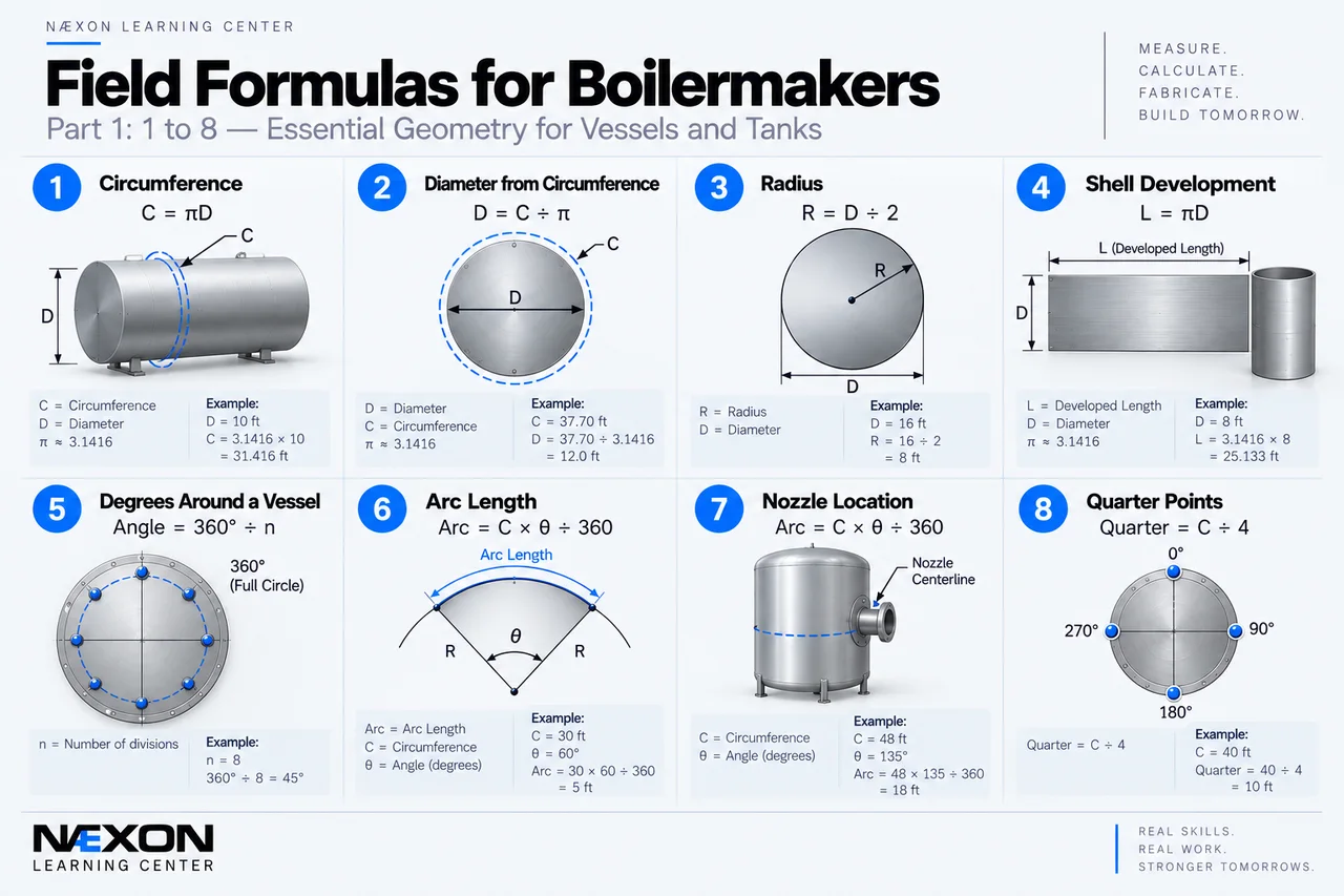
Figure 1. Field Formulas for Boilermakers — Formulas 1–8: Essential vessel and tank geometry covering circumference, diameter, radius, shell development, degrees around a vessel, arc length, nozzle location, and quarter points. These calculations help boilermakers accurately develop plate, establish reference points, and position attachments around cylindrical equipment.
One of the most important formulas in boilermaker work is:
C = πD
Where:
C = circumference
D = diameter
π ≈ 3.1416
Example
A vessel has a diameter of:
10 ft
Circumference:
C = 3.1416 × 10
C = 31.416 ft
That is approximately:
31 ft 5 in
Circumference is fundamental when laying out shell courses, nozzles, clips, platforms, ladders, stiffeners, and other attachments around cylindrical equipment.
2. Finding Diameter From Circumference
The circumference formula can be reversed:
D = C ÷ π
Example
Measured circumference:
37.70 ft
Diameter:
D = 37.70 ÷ 3.1416
D ≈ 12 ft
This is useful when wrapping a tape around a vessel is practical but measuring directly across its diameter is not.
Always make sure the circumference measurement and the required diameter reference correspond to the same surface.
3. Finding Radius
Radius is half the diameter:
R = D ÷ 2
Working backward:
D = 2R
Example
Diameter:
16 ft
Radius:
16 ÷ 2
= 8 ft
Radius is important for circular layouts, heads, shell geometry, nozzles, curved plate, chord calculations, and sagitta calculations.
4. Shell Development
If a cylindrical shell could theoretically be cut along one straight longitudinal line and laid flat, its developed circumferential length would be based on:
Developed Length = πD
Example
Diameter:
8 ft
Developed Length = 3.1416 × 8
≈ 25.133 ft
This is the basic geometric relationship.
Actual fabrication can be more complicated.
Depending on the drawing and fabrication method, development may be based on the inside diameter, outside diameter, mean diameter, or another specified reference. Plate thickness, forming allowances, seam configuration, weld preparation, and fabrication tolerances can also matter.
Never assume which diameter controls the developed plate length. Verify the drawing and fabrication procedure.
5. Degrees Around a Vessel
A complete circle contains:
360°
For equally spaced components:
Degrees per Division = 360° ÷ Number of Divisions
Example
Eight clips must be equally spaced around a vessel.
360° ÷ 8
= 45°
Each clip is theoretically:
45° apart
For 12 equally spaced locations:
360° ÷ 12
= 30°
This is one of the quickest methods for laying out equally spaced attachments around cylindrical equipment.
6. Arc Length
Sometimes an angular location must be converted into an actual measurement around the vessel shell.
Use:
Arc Length = Circumference × Angle ÷ 360
Example
Vessel circumference:
30 ft
Required rotation:
60°
Arc Length = 30 × 60 ÷ 360
= 5 ft
A 60° movement around that shell therefore represents:
5 ft along the circumference
This is especially useful when laying out nozzles and attachments using a wraparound measurement.
7. Locating a Nozzle Around a Shell
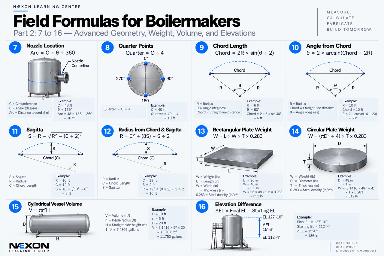
Figure 2. Field Formulas for Boilermakers — Formulas 7–16: Advanced vessel and fabrication calculations covering nozzle location, quarter points, chord length, angle from chord, sagitta, radius, rectangular and circular plate weight, cylindrical vessel volume, and elevation differences. These formulas help boilermakers accurately lay out vessels, verify curved geometry, estimate material weight, calculate capacity, and establish critical field dimensions.
Suppose a vessel has a circumference of:
48 ft
A nozzle centerline is located:
135°
from the established 0° reference.
Use:
Arc Distance = C × θ ÷ 360
= 48 × 135 ÷ 360
= 18 ft
The theoretical nozzle centerline is:
18 ft around the circumference from 0°
in the direction specified by the drawing.
Before marking the vessel, verify the drawing’s orientation.
A nozzle shown at 135° can be placed incorrectly even when the calculation is perfect if the wrong zero point, viewing direction, or direction of rotation is used.
8. Quarter Points
Four fundamental positions around a vessel are:
0°
90°
180°
270°
Each represents one quarter of the circumference.
Therefore:
Quarter Circumference = C ÷ 4
Example
Circumference:
40 ft
40 ÷ 4 = 10 ft
Starting from 0°, the quarter points occur every:
10 ft around the shell
Quarter points provide useful references for checking vessel orientation and establishing additional layout locations.
9. Chord Length
An arc follows the curved surface.
A chord is the straight-line distance between two points on a circle.
Chord length is calculated using:
Chord = 2R × sin(θ ÷ 2)
Where:
R = radius
θ = central angle between the points
Example
Radius:
6 ft
Angle:
60°
Chord = 2 × 6 × sin 30°
Chord = 12 × 0.5
Chord = 6 ft
Chord measurements can be extremely useful because a boilermaker may be able to pull a straight tape between two layout points even when measuring accurately around the curved shell is difficult.
10. Finding an Angle From a Chord
The chord formula can be reversed.
If the radius and chord are known:
θ = 2 × arcsin(Chord ÷ 2R)
Example
Radius:
10 ft
Chord:
10 ft
θ = 2 × arcsin(10 ÷ 20)
θ = 2 × arcsin(0.5)
θ = 2 × 30°
θ = 60°
This allows an angular position to be checked from a straight-line measurement.
11. Sagitta
The sagitta is the perpendicular distance from the midpoint of a chord to the arc.
For radius R and chord length C:
S = R − √(R² − (C ÷ 2)²)
Where:
S = sagitta
R = radius
C = chord length
Example
Radius:
10 ft
Chord:
12 ft
S = 10 − √(10² − 6²)
= 10 − √(100 − 36)
= 10 − √64
= 10 − 8
= 2 ft
Sagitta is useful when laying out or checking curved plate and large-radius components.
12. Finding Radius From Chord and Sagitta
Sometimes the center point of a large radius is inaccessible.
If the chord and sagitta can be measured, the radius can be calculated:
R = C² ÷ (8S) + S ÷ 2
Example
Chord:
12 ft
Sagitta:
2 ft
R = 12² ÷ (8 × 2) + 2 ÷ 2
= 144 ÷ 16 + 1
= 9 + 1
= 10 ft
This is a powerful field relationship because it allows a large radius to be determined without physically locating the center of the circle.
13. Rectangular Plate Weight
Approximate steel weight can be calculated using:
Weight = Volume × Density
A commonly used approximate density for carbon steel is:
0.283 lb/in³
For rectangular plate:
Weight ≈ Length × Width × Thickness × 0.283
when all dimensions are in inches.
Example
Plate dimensions:
96 in × 48 in × 1/2 in
Volume:
96 × 48 × 0.5
= 2,304 in³
Approximate weight:
2,304 × 0.283
≈ 652 lb
This is an estimate. Material grade, cutouts, attachments, stiffeners, clips, weld metal, and other components can change actual weight.
For lifting operations, use verified weights and approved rigging information whenever available.
14. Circular Plate Weight
For a circular plate, first calculate its area:
A = πD² ÷ 4
Then:
Volume = Area × Thickness
Finally:
Weight = Volume × Density
Example
Diameter:
48 in
Thickness:
1 in
Area:
A = 3.1416 × 48² ÷ 4
≈ 1,809.6 in²
Volume:
≈ 1,809.6 in³
Approximate carbon-steel weight:
1,809.6 × 0.283
≈ 512 lb
Again, this is a theoretical estimate for a solid circular plate without holes, cutouts, attachments, or other modifications.
15. Cylindrical Vessel Volume
For the cylindrical portion of a vessel:
V = πr²H
Where:
V = volume
r = inside radius
H = internal cylindrical height
Example
Inside diameter:
10 ft
Radius:
5 ft
Straight-side height:
20 ft
V = 3.1416 × 5² × 20
V ≈ 1,570.8 ft³
To estimate U.S. gallons:
1 ft³ ≈ 7.4805 U.S. gal
Therefore:
1,570.8 × 7.4805
≈ 11,750 gallons
This represents only the cylindrical geometry used in the calculation.
Heads, cones, internals, dead space, nozzles, operating levels, and other geometry can change actual vessel capacity.
16. Elevation Difference
Boilermakers constantly work from elevation marks.
The basic calculation is:
Elevation Difference = Final Elevation − Starting Elevation
Example
Lower reference:
EL 112’-4”
Upper reference:
EL 127’-10”
Difference:
15’-6”
or:
186 in
Elevation differences can establish shell-course locations, nozzle centerlines, platform elevations, support locations, stiffening rings, structural attachments, and equipment connections.
Always verify exactly what the elevation references—bottom of steel, top of steel, centerline, tangent line, finished grade, or another established datum.
The Arc vs. Chord Trap
One of the easiest mistakes in circular layout is confusing arc length with chord length.
Imagine two points located 60° apart on a vessel with a radius of:
10 ft
First calculate circumference:
C = 2πR
= 2 × 3.1416 × 10
≈ 62.832 ft
The 60° arc is:
Arc = 62.832 × 60 ÷ 360
≈ 10.472 ft
Now calculate the chord:
Chord = 2 × 10 × sin 30°
= 10 ft
Difference:
10.472 − 10
= 0.472 ft
or approximately:
5.66 in
That is more than five inches of difference between two measurements referencing exactly the same two points.
The arc follows the shell.
The chord cuts straight across between the points.
On large-diameter equipment, confusing them can put a nozzle or attachment significantly out of position.
Reading Vessel Orientation Correctly
The mathematics can be perfect and the layout can still be wrong if the reference direction is misunderstood.
Vessel drawings may establish locations using compass directions such as North, South, East, and West, or angular positions such as 0°, 90°, 180°, and 270°.
Before transferring an angular dimension onto the vessel, verify:
- The established 0° reference.
- The direction from which the drawing is viewed.
- Whether angles increase clockwise or counterclockwise.
- Whether the view is from the top, bottom, inside, or outside.
- Whether the location refers to a nozzle centerline, edge, bolt orientation, or another reference.
- Whether the measurement should follow the shell as an arc or span directly between points as a chord.
Viewing direction is especially important.
A layout that appears clockwise when viewed from one end can appear counterclockwise when viewed from the opposite end.
Never assume the orientation.
Common Boilermaker Math Mistakes
Several simple mistakes can create major layout problems on large equipment:
- Confusing radius with diameter.
- Measuring a chord when the drawing requires an arc.
- Measuring an arc when the drawing requires a chord.
- Starting angular layout from the wrong 0° reference.
- Going clockwise when the drawing specifies counterclockwise.
- Reading a nozzle orientation from the wrong viewing direction.
- Using outside diameter when another diameter controls the calculation.
- Ignoring plate thickness when development depends on the specified reference surface.
- Mixing feet and inches.
- Mixing degrees with linear measurements.
- Dividing 360° by the wrong number of spaces.
- Rounding calculations too early.
- Calculating plate weight without accounting for attached material.
- Assuming theoretical vessel volume equals usable operating capacity.
- Cutting or welding before verifying the layout against the drawing.
Field Rules
Establish zero first.
Every angular measurement around a vessel depends on a known reference.
Know the viewing direction.
Clockwise and counterclockwise depend on where you are looking from.
Arc and chord are different.
Know which measurement the drawing requires before pulling the tape.
Use the correct diameter.
Inside diameter, outside diameter, and other specified reference diameters are not automatically interchangeable.
Check quarter points.
The 0°, 90°, 180°, and 270° positions provide excellent references for verifying circular layout.
Use chord measurements as a check when appropriate.
A straight-line measurement between established points can provide an independent geometric verification.
Keep units consistent.
Do not mix inches and feet inside an equation without converting them first.
Do not round too early.
Carry enough precision through the calculation and round the final result according to the required field tolerance.
Calculate weight before moving steel.
But use verified weights and approved lift information for actual lifting operations.
The drawing controls.
Field formulas explain the geometry. They do not replace engineering, fabrication drawings, specifications, or approved procedures.
Knowledge Check
1. What is the circumference of a 10-ft diameter vessel?
C = π × 10
≈ 31.416 ft
2. Eight attachments are equally spaced around a shell. What is their angular spacing?
360° ÷ 8 = 45°
3. What is the difference between an arc and a chord?
An arc follows the curved circumference, while a chord is the straight-line distance between two points on the circle.
4. What is the approximate weight of 1,000 in³ of carbon steel using 0.283 lb/in³?
1,000 × 0.283 = 283 lb
5. What formula calculates the cylindrical portion of a vessel’s volume?
V = πr²H
6. A 24-ft circumference is divided into four equal sections. What is the distance around the shell between each quarter point?
24 ÷ 4 = 6 ft
7. What should be established before laying out angular locations around a vessel?
The correct 0° reference and drawing orientation.
Practical Exercise
A cylindrical vessel has:
Diameter = 12 ft
A nozzle must be positioned:
120° from the 0° reference
Step 1 — Calculate Circumference
C = πD
C = 3.1416 × 12
C ≈ 37.699 ft
Step 2 — Calculate Arc Distance
Arc Length = C × θ ÷ 360
= 37.699 × 120 ÷ 360
≈ 12.566 ft
The nozzle centerline is therefore approximately:
12.57 ft around the shell from 0°
in the direction specified by the drawing.
Step 3 — Calculate the Chord
Radius:
R = 12 ÷ 2
R = 6 ft
Now:
Chord = 2R × sin(θ ÷ 2)
= 2 × 6 × sin 60°
≈ 10.392 ft
So:
Arc Length ≈ 12.566 ft
Chord Length ≈ 10.392 ft
Both dimensions reference the same two angular locations.
But they measure two completely different paths.
Field Challenge
A vessel has an outside diameter of:
16 ft
Four support clips must be equally spaced around the shell.
One clip establishes the 0° reference.
Step 1 — Find the Circumference
C = πD
C = 3.1416 × 16
C ≈ 50.266 ft
Step 2 — Find Angular Spacing
Four equally spaced clips:
360° ÷ 4
= 90°
The theoretical locations are:
0°
90°
180°
270°
Step 3 — Find Distance Around the Shell
Quarter circumference:
50.266 ÷ 4
≈ 12.566 ft
Each successive clip is therefore approximately:
12.566 ft around the circumference
from the previous clip.
Step 4 — Verify With a Chord
Radius:
16 ÷ 2
= 8 ft
For adjacent clips 90° apart:
Chord = 2R × sin(θ ÷ 2)
= 2 × 8 × sin 45°
≈ 11.314 ft
Therefore:
Arc between clips ≈ 12.566 ft
Straight chord between clips ≈ 11.314 ft
The two measurements should not be confused.
One follows the curved shell.
The other provides a straight-line geometric check.
Final Takeaway
Boilermaker math is geometry wrapped around steel.
Remember:
Circumference → C = πD
Diameter → D = C ÷ π
Radius → R = D ÷ 2
Equal spacing → 360° ÷ number of divisions
Arc length → C × θ ÷ 360
Chord → 2R × sin(θ ÷ 2)
Sagitta → R − √(R² − (C ÷ 2)²)
Radius from chord and sagitta → C² ÷ (8S) + S ÷ 2
Plate weight → Volume × Density
Cylindrical volume → πr²H
Elevation difference → Final Elevation − Starting Elevation
Most importantly:
Establish the reference before you establish the measurement.
A good boilermaker can follow the marks.
A great boilermaker understands the geometry that put those marks there.


