
Millwright work is precision work. Installing a pump, aligning shafts, setting machinery, changing sheaves, checking gearboxes, or troubleshooting rotating equipment often comes down to measurements that may be only a few thousandths of an inch.
The machinery may weigh thousands of pounds, but a very small alignment error can still matter.
That is why millwrights need to understand the relationships behind RPM, ratios, torque, horsepower, shaft alignment, thermal growth, pulley speed, mechanical advantage, and precision measurement.
These formulas are practical field references. Equipment drawings, manufacturer specifications, engineered tolerances, alignment procedures, lubrication requirements, and site safety procedures always control the actual work.
1. Gear Ratio
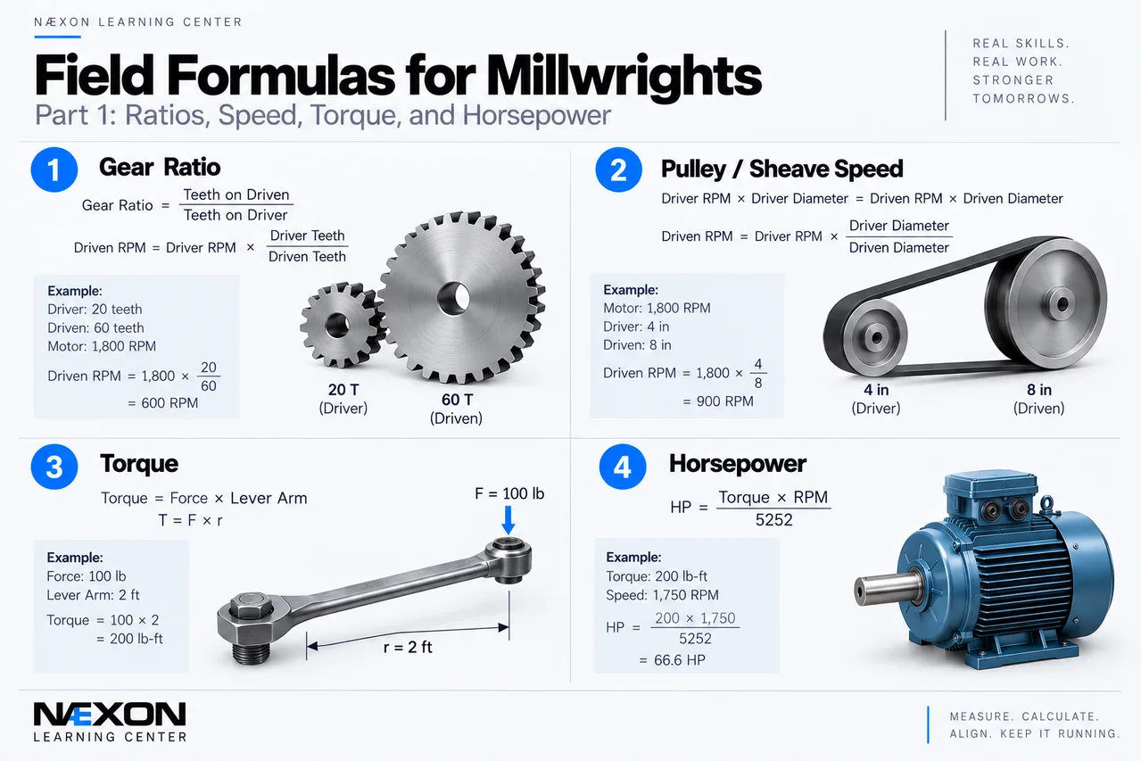
Figure 1. Field Formulas for Millwrights — Formulas 1–4: Essential rotating-equipment calculations covering gear ratio, pulley and sheave speed, torque, and horsepower. These relationships help millwrights understand how changes in speed, gear or sheave size, and mechanical leverage affect industrial machinery and drive systems.
For a simple pair of external gears:
Gear Ratio = Teeth on Driven Gear ÷ Teeth on Driver Gear
The corresponding ideal speed relationship is:
Driven RPM = Driver RPM × Driver Teeth ÷ Driven Teeth
Example
Driver:
20 teeth
Driven:
60 teeth
Gear ratio:
60 ÷ 20 = 3
This is a:
3:1 reduction
If the driver rotates at:
1,800 RPM
then:
Driven RPM = 1,800 × 20 ÷ 60
= 600 RPM
The output rotates slower, while ideal torque increases proportionally before losses.
2. Finding RPM From Gear Ratio
For an ideal speed reducer expressed as an input-to-output reduction ratio:
Output RPM = Input RPM ÷ Reduction Ratio
Example
Motor speed:
1,750 RPM
Reducer:
5:1
Output RPM = 1,750 ÷ 5
= 350 RPM
To work backward:
Input RPM = Output RPM × Reduction Ratio
Understanding the direction of the ratio matters. Always verify how a manufacturer defines a published ratio.
3. Pulley and Sheave Speed
For a simple belt drive with no slip:
Driver RPM × Driver Diameter = Driven RPM × Driven Diameter
Therefore:
Driven RPM = Driver RPM × Driver Diameter ÷ Driven Diameter
Example
Driver sheave:
4 in
Driven sheave:
8 in
Motor:
1,800 RPM
Driven RPM = 1,800 × 4 ÷ 8
= 900 RPM
Doubling the driven sheave diameter theoretically cuts its speed in half.
4. Finding Required Sheave Diameter
The same relationship can be rearranged.
Driven Diameter = Driver RPM × Driver Diameter ÷ Desired Driven RPM
Example
Motor:
1,800 RPM
Driver sheave:
5 in
Desired equipment speed:
1,200 RPM
Driven Diameter = 1,800 × 5 ÷ 1,200
= 7.5 in
Actual selection must use approved sheave sizes, belt-drive design requirements, equipment speed limits, and manufacturer specifications.
5. Torque
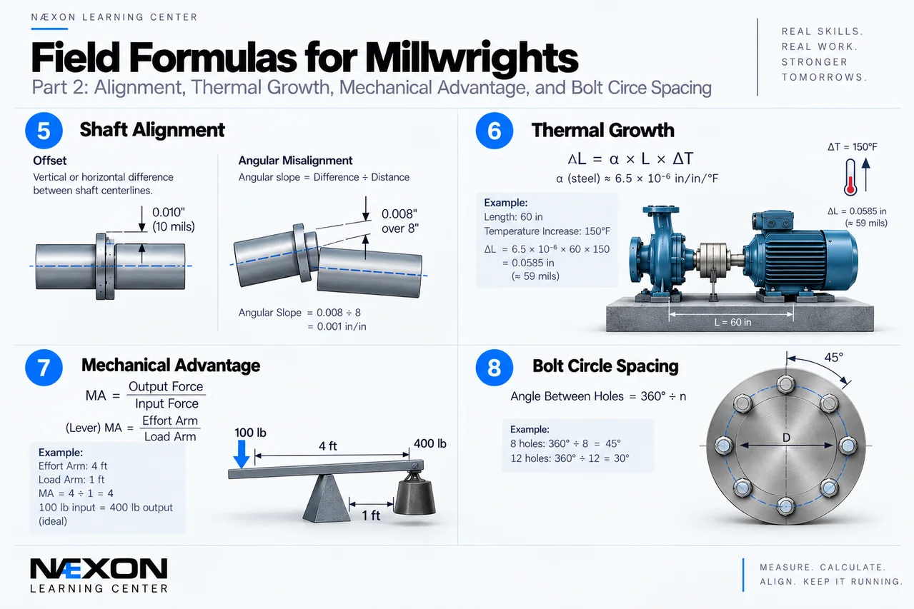
Figure 2. Field Formulas for Millwrights — Formulas 5–8: Essential precision and mechanical calculations covering shaft offset and angular misalignment, thermal growth, mechanical advantage, and bolt-circle spacing. These relationships help millwrights accurately align rotating equipment, anticipate temperature-related movement, understand force multiplication, and lay out evenly spaced bolt patterns.
Torque describes a turning moment.
For a perpendicular force:
Torque = Force × Lever Arm
or:
T = F × r
Example
A force of:
100 lb
is applied perpendicular to a:
2 ft lever
Torque = 100 × 2
= 200 lb-ft
Double the effective lever arm and the same force produces twice the torque.
6. Horsepower From Torque and RPM
For rotating equipment using torque in lb-ft:
HP = Torque × RPM ÷ 5252
Example
Shaft torque:
200 lb-ft
Speed:
1,750 RPM
HP = 200 × 1,750 ÷ 5252
≈ 66.6 HP
The equation can also be reversed:
Torque = HP × 5252 ÷ RPM
This relationship is extremely useful when understanding motors, gearboxes, conveyors, pumps, fans, and other rotating machinery.
7. Torque From Horsepower
Suppose a shaft transmits:
100 HP
at:
1,750 RPM
Torque = 100 × 5252 ÷ 1,750
≈ 300 lb-ft
Now imagine the same 100 HP at:
350 RPM
Torque = 100 × 5252 ÷ 350
≈ 1,501 lb-ft
The power is the same.
The speed is lower.
The torque is dramatically higher.
That is one reason speed reducers are so useful.
8. Mechanical Advantage
For an ideal simple machine:
Mechanical Advantage = Output Force ÷ Input Force
For a simple lever:
MA = Effort Arm ÷ Load Arm
Example
Effort arm:
4 ft
Load arm:
1 ft
MA = 4 ÷ 1
= 4
Ignoring losses, 100 lb of input force could theoretically produce:
400 lb of output force
Real systems have friction and other losses, so actual performance will be lower.
9. Shaft Offset
In shaft alignment, offset describes the displacement between shaft centerlines at a reference plane.
If one shaft centerline is:
0.010 in
above the other at the measured location, the vertical offset is:
10 thousandths
or:
10 mils
Because:
1 mil = 0.001 in
Therefore:
0.010 in = 10 mils
This is why millwrights must be comfortable moving between decimal inches and thousandths.
10. Angular Misalignment
Angular misalignment can be represented by the difference in readings across a known distance.
A simplified small-angle relationship is:
Angular Slope = Difference ÷ Measurement Distance
Example
Difference:
0.008 in
Measurement distance:
8 in
Angular Slope = 0.008 ÷ 8
= 0.001 in/in
This means the centerline changes approximately:
0.001 in per inch
over that geometry.
Actual alignment corrections depend on the measurement method, machine geometry, coupling arrangement, measurement planes, and alignment system being used.
11. Foot Correction From Angular Error
Once an angular slope is established, a simplified geometric correction at another axial location is:
Correction = Angular Slope × Distance
Example
Angular slope:
0.001 in/in
Distance to a machine foot:
12 in
Correction = 0.001 × 12
= 0.012 in
or:
12 mils
This illustrates why a small angular error at the coupling can produce a much larger positional difference farther away.
12. Soft Foot
Soft foot can be evaluated by measuring the change observed at a machine foot when the hold-down condition changes according to the approved procedure.
A simple difference calculation is:
Soft-Foot Movement = Final Reading − Initial Reading
Example
Initial indicator reading:
0.001 in
Reading after controlled loosening:
0.007 in
Difference:
0.006 in
or:
6 mils
Whether that condition is acceptable depends on the equipment and alignment specification.
Soft foot should be corrected appropriately before final precision alignment.
13. Thermal Growth
Machines can change position as their temperature changes.
A simplified linear thermal-expansion relationship is:
ΔL = α × L × ΔT
Where:
ΔL = change in length
α = coefficient of thermal expansion
L = original length
ΔT = temperature change
For carbon steel, a commonly used approximate coefficient is:
6.5 × 10⁻⁶ in/in/°F
The appropriate material value should be verified for actual calculations.
Example
Steel dimension:
60 in
Temperature increase:
150°F
ΔL = 6.5 × 10⁻⁶ × 60 × 150
≈ 0.0585 in
That is nearly:
59 mils
of theoretical growth.
This helps explain why some machines are intentionally aligned cold to specified offsets so that operating thermal growth moves them toward the desired running alignment.
14. Thermal Growth Between Two Machines
The important issue is often not simply how much one machine grows.
It is the difference in movement between connected machines at the relevant shaft centerlines.
Conceptually:
Relative Growth = Growth of Machine A − Growth of Machine B
If Machine A rises:
0.040 in
and Machine B rises:
0.015 in
then their relative vertical change is:
0.040 − 0.015
= 0.025 in
or:
25 mils
The required cold alignment target should come from the equipment manufacturer, engineering data, or approved alignment specification—not from assumption.
15. Converting Thousandths
Millwrights routinely work in thousandths of an inch.
0.001 in = 1 mil
0.005 in = 5 mils
0.010 in = 10 mils
0.025 in = 25 mils
0.100 in = 100 mils
A measurement of:
0.003 in
may look insignificant on a tape measure.
In precision machinery alignment, it can be important.
16. Percent Speed Change
When machinery speed changes:
Speed Change % = (New RPM − Original RPM) ÷ Original RPM × 100
Example
Original:
1,000 RPM
New:
1,100 RPM
(1,100 − 1,000) ÷ 1,000 × 100
= 10%
The speed increased:
10%
A speed change can affect equipment performance, vibration behavior, belt speed, fan performance, pump behavior, and other system characteristics. Do not change equipment speed without the appropriate engineering or manufacturer authorization.
The Alignment Trap
Imagine two shafts appear perfectly centered at the coupling face.
That does not necessarily mean the machines are aligned.
They could have nearly zero offset at that location while their centerlines are angularly misaligned.
Move farther away from the coupling and the centerlines continue separating.
For example:
Angular slope:
0.001 in/in
Distance:
20 in
Difference:
0.001 × 20
= 0.020 in
That is:
20 mils
The lesson is important:
Offset and angular misalignment are different conditions.
A precision alignment must account for both according to the specified alignment method.
Common Millwright Math Mistakes
Common mistakes include:
- Reversing driver and driven ratios.
- Confusing diameter ratio with RPM ratio.
- Mixing inch-pounds and foot-pounds.
- Using 5252 with incompatible units.
- Confusing 0.001 in with 0.01 in.
- Treating mils as millimeters.
- Correcting angular misalignment as though it were only offset.
- Ignoring soft foot before alignment.
- Ignoring thermal growth.
- Moving the wrong machine or wrong foot.
- Forgetting the distance between measurement and correction planes.
- Assuming cold zero-zero alignment is always the correct operating target.
- Making speed or drive changes without checking equipment limits.
Field Rules
Know the driver and driven components.
Before using a ratio, identify which component provides the input.
Track your units.
RPM, horsepower, lb-ft, inches, mils, millimeters, and temperature units must remain consistent with the formula being used.
One mil means one thousandth.
1 mil = 0.001 in
Correct soft foot first.
Trying to precision-align a machine with unresolved soft foot can waste time and produce unreliable results.
Offset and angle are different.
A machine can have one, the other, or both.
Consider operating condition.
Cold alignment targets may intentionally differ from running alignment because of thermal movement and other operating effects.
Verify manufacturer requirements.
A mathematical answer does not establish an acceptable machinery tolerance.
Knowledge Check
1. A 20-tooth driver turns a 60-tooth driven gear. What is the reduction ratio?
3:1
2. A 1,800 RPM motor drives a sheave twice the driver’s diameter. Ignoring slip, what is driven speed?
900 RPM
3. How many thousandths are in 0.012 in?
12 mils
4. What happens to ideal torque when horsepower remains constant and RPM decreases?
Torque increases.
5. What two basic alignment conditions must millwrights distinguish?
Offset and angular misalignment.
Practical Exercise
A motor operates at:
1,800 RPM
and drives a:
4-in sheave
The driven machine has an:
8-in sheave
Calculate driven speed:
Driven RPM = 1,800 × 4 ÷ 8
= 900 RPM
Now suppose the shaft transmits:
50 HP
at approximately 900 RPM.
Calculate theoretical torque:
Torque = 50 × 5252 ÷ 900
≈ 292 lb-ft
The belt drive reduced the speed.
At the lower speed, the same transmitted horsepower corresponds to greater shaft torque.
That relationship is at the heart of countless industrial drive systems.
Final Takeaway
Millwright math is the math of movement, force, and precision.
Remember:
Gear ratio → teeth relationship.
Belt speed ratio → sheave diameter relationship.
Torque → force × distance.
Horsepower → torque × RPM ÷ 5252.
1 mil → 0.001 inch.
Angular error grows with distance.
Thermal growth can change alignment.
Soft foot should be addressed before final alignment.
A good millwright can move a machine into place.
A great millwright can measure what the machine is doing in thousandths of an inch—and understand why.


