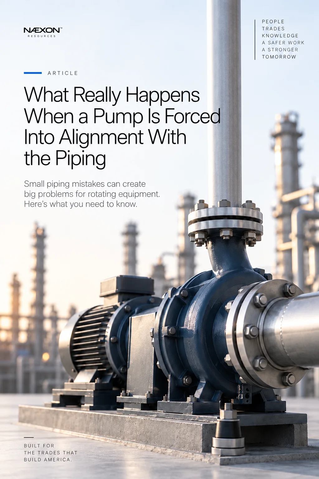
A centrifugal pump can be perfectly aligned with its driver, but that alignment can change when the suction and discharge piping are connected. The coupling may move, the pump casing may shift, or alignment readings that were previously acceptable may suddenly fall outside tolerance. In the field, this is sometimes followed by a dangerous assumption: if the piping flange is close enough, just install the bolts and pull it into position.
That approach can turn a piping problem into a machinery problem. Piping connected to rotating equipment should arrive at the equipment in the position required by the design rather than depending on flange bolts to force the connection together. When significant force is required to align piping with a pump nozzle, that force does not disappear after the bolts are tightened. It remains in the connected system and can impose loads on the pump.
The consequences may not appear immediately. The pump may start normally and continue running for weeks or months, but underneath that apparently successful installation, the machine may be operating while continuously resisting forces from the piping. Understanding this relationship is important for both pipefitters and millwrights because the two trades meet at one critical location: the equipment nozzle.
Understanding What the Pump Actually Is
A pump should never be treated as another piece of pipe with two flanges attached. Inside a typical centrifugal pump, a rotating shaft drives an impeller while bearings maintain the position of the rotating assembly. Mechanical seals or another sealing arrangement control leakage where the rotating shaft interacts with the pressure-containing equipment, and the pump shaft is usually connected to an electric motor or another driver through a coupling.
These components depend on mechanical relationships that can be affected by relatively small movements. If piping places unwanted loads on a pump nozzle, the casing can potentially move or distort enough to influence shaft alignment, coupling condition, bearings, seals or other components. This is why the pump nozzle should not become the anchor point used to correct improperly positioned piping.
What Pipe Strain Means in the Field
Pipe strain is a common field term used to describe unwanted forces and moments that connected piping can impose on equipment. Imagine that a discharge pipe flange arrives approximately half an inch above the pump nozzle. Instead of correcting the piping condition, bolts are installed and progressively tightened until the pipe flange is pulled downward and the two flange faces meet.
From several feet away, the finished connection may look completely normal. The problem is that the force required to move the piping did not disappear when the bolts were tightened. The piping still has a tendency to return toward its previous position, while the connected equipment and piping system are now resisting that movement.
A bolted flange therefore does not automatically prove that a piping connection is correct. It only proves that the two flange faces were physically brought together.
Flange Bolts Are Not Alignment Tools
Flange bolts are intended to produce the required clamping force in a properly assembled joint. They should not be treated as miniature come-alongs for correcting significant piping misalignment. If substantial force is required to bring piping into position, the better response is to determine why the piping is not where it is supposed to be.
The cause might be a fabrication error, incorrect field measurement, wrong fitting takeoff, incorrect support elevation, improperly adjusted support, equipment-position discrepancy, installation-sequence issue or another part of the piping system being incorrectly positioned. Temperature and engineered thermal movement can also affect how a piping system is intended to sit under different operating conditions.
Pulling the flange into position with bolts may hide the visible symptom without correcting the underlying problem.
Field Rule: Do not use the equipment nozzle to finish fabricating the piping system.
What Can Happen to Pump Alignment
Consider a pump and motor that have already been positioned and aligned by the millwrights. The shafts have been brought within the required alignment criteria, and everything appears ready for the piping connections. When the piping is attached, however, excessive piping loads can move the pump casing. That movement may be almost impossible to see with the naked eye while still being measurable at the coupling.
This is where the working tolerances of different trades become important. Pipefitters routinely work with fractions of an inch, while millwrights performing precision alignment may be concerned with movement measured in thousandths of an inch. Something that looks insignificant during piping installation can therefore matter considerably to rotating equipment.
If the pump moves after the piping is connected, the relationship between the pump and driver shafts can change. Offset misalignment can occur when the shaft centerlines remain generally parallel but are displaced from one another, while angular misalignment occurs when the shaft centerlines are positioned at an angle. Actual machinery conditions can contain combinations of both.
A Flexible Coupling Does Not Make Misalignment Disappear
Flexible couplings are designed to accommodate specified amounts and types of movement, but that does not mean alignment stops mattering. A flexible coupling should never become an excuse for poor machinery installation. Excessive misalignment can contribute to unwanted loading, vibration, heat and accelerated wear, depending on the equipment and operating conditions.
The acceptable alignment criteria depend on the machinery, coupling, operating temperature, speed, manufacturer requirements and applicable project specifications. The practical lesson for the field is much simpler: do not assume the coupling will compensate for whatever the piping does to the pump.
Bearings and Mechanical Seals May Pay the Price
Pump bearings are designed to support the rotating assembly under expected operating conditions. When installation problems introduce additional forces into the machinery system, bearing loading and machine behavior can potentially be affected. Over time, problems may appear as vibration, abnormal temperatures, shortened bearing life or recurring maintenance.
Mechanical seals can also be sensitive to machinery condition. They operate with carefully controlled relationships between rotating and stationary components, and adverse movement or distortion can potentially influence seal performance. This means a pump that repeatedly experiences bearing or seal problems deserves more investigation than simply replacing the failed component.
A recurring sequence of seal replacement, realignment, restart and another seal failure should eventually raise a larger question: why does this pump keep experiencing the same problem? The component that fails is not necessarily the component that originally caused the failure.
The Pipefitter and Millwright Need Each Other
Rotating-equipment connections are one of the clearest examples of why refinery trades should not work in isolation. The pipefitter understands the piping system, while the millwright understands the machinery. Both systems meet at the pump nozzle, and both trades can provide information the other needs.
A pipefitter may look at a flange and see that it only needs to move slightly before the bolts will enter. A millwright may see that same movement immediately register in alignment readings. Neither perspective should be ignored. A quality installation requires the piping and machinery to work together as one mechanical system.
When machinery alignment changes significantly as piping is connected, that change is valuable information. Instead of immediately moving the machine again to compensate, the crew should investigate why the piping connection is influencing the equipment. Otherwise, the pump can effectively be aligned against the piping load while the underlying condition remains trapped in the system.
Field Rule: If connecting the pipe moves the machine, investigate the piping before simply moving the machine.
The Problem May Be Farther Down the Pipe
When a flange does not naturally arrive where expected, the problem is not necessarily in the final spool. The cause may exist several feet—or several supports—away from the equipment.
Pipe supports help establish and control piping position and movement according to the system design. A support installed at the wrong elevation, incorrectly adjusted, missing, binding or otherwise inconsistent with the design can influence the position of piping near the pump. Temporary rigging can also change the apparent position of a line during installation.
This is why experienced pipefitters do not always stare at the flange when the flange is wrong. They step back and look at the system. The problem visible at the pump may have originated somewhere else.
Suction Piping Deserves Special Attention
Pump suction piping involves more than simply achieving a mechanically acceptable flange connection. Its configuration can also influence pump performance. Restrictions, unfavorable geometry, trapped vapor, inappropriate transitions or other system conditions can contribute to operating problems depending on the service and design.
A suction flange that bolts perfectly to the pump therefore does not automatically mean the suction system is correct. The piping must satisfy the mechanical installation requirements while also remaining consistent with the process and hydraulic design.
This is another reason pipefitters benefit from understanding what happens beyond the flange. The pipe is not simply delivering fluid to another connection; it is feeding a machine whose performance can depend heavily on the conditions at its inlet.
Cold Position Is Not Always Operating Position
Industrial piping can move significantly as temperature changes. Hot piping expands, cold systems may contract, and engineered piping systems use flexibility, guides, anchors, supports, loops, expansion devices where appropriate and other design features to control that movement.
Rotating equipment may also experience predictable movement between ambient and operating conditions. Alignment procedures can account for expected operating movement depending on the machinery and installation.
For this reason, field crews should not casually modify a piping arrangement simply because something appears unusual while the system is cold. The correct position should be determined from the engineering documents, equipment requirements and applicable installation procedure rather than appearance alone.
Field Rule: Never modify engineered piping simply because the cold position looks unusual. Verify the design first.
A Typical Turnaround Problem
Imagine a refinery turnaround where an existing pump has been replaced. The millwrights position the new pump and motor and establish preliminary alignment. Pipefitters begin reconnecting the suction piping, and the suction flange comes into position without significant difficulty. The crew then moves to the discharge spool and discovers that the discharge flange sits approximately 3/8 inch away from where it needs to be.
The bolt holes are close enough that someone could probably install the bolts and pull the flange into position. That is exactly when the crew should resist the temptation to make the problem disappear. The three-eighths-inch discrepancy is information, and once the flange is forcibly connected, some of that information may become harder to recognize.
The crew should verify the spool dimensions, fitting takeoffs, flange orientation, pump position, support conditions, equipment elevation, temporary rigging and applicable drawings. The millwrights should be involved because they can determine whether the machinery position or alignment is being affected as the piping condition is evaluated.
The objective should not simply be to get the bolts through the holes. The objective is to install the piping without creating an unacceptable condition at the machine.
“It Bolted Up Fine” Does Not Prove the Installation Is Correct
One of the most misleading statements around rotating equipment is that a connection must be acceptable because it bolted together successfully. A flange can be physically assembled while still imposing unwanted forces or moments on the connected equipment. The bolts only demonstrate that enough force was available to bring the components together.
This distinction separates assembly from installation. Assembly means the pieces were connected. Proper installation means the equipment and piping were connected in accordance with the design, applicable tolerances, specifications and procedures without creating unacceptable conditions.
A skilled craftsperson is not satisfied simply because the bolts went in. The better question is whether the piping arrived where the design intended it to arrive.
When the Same Pump Keeps Failing
Recurring machinery problems should encourage system-level troubleshooting. Imagine a pump that repeatedly experiences mechanical-seal failures, bearing problems, elevated vibration or alignment changes. Maintenance repairs the immediate problem, restarts the equipment and eventually experiences another similar failure.
At some point, the crew should look beyond the component being replaced. The investigation may include base condition, soft foot, coupling condition, lubrication, operating conditions, cavitation, piping loads, support condition, thermal movement and other potential contributors. The exact cause requires proper evaluation rather than assumption, but repeated failures are valuable clues.
The failed bearing or seal may be telling you that something else is wrong.
Pipefitters Should Understand Machinery
A pipefitter does not need to become a millwright to benefit from understanding rotating equipment. The important lesson is that not every equipment nozzle should be treated the same way. A piping connection to a storage tank creates different considerations than piping connected to a high-speed rotating machine.
Pumps, compressors, turbines, exchangers, control valves and pressure vessels all introduce different installation considerations. Understanding what happens beyond the flange helps the pipefitter recognize why dimensions, supports, orientation, alignment and installation sequence matter.
The same principle applies in reverse. When machinery alignment changes or equipment repeatedly experiences problems, millwrights should look beyond the coupling and consider the systems connected to the machine. Sometimes the most important machinery clue is several feet away in the piping.
Field Rules
- Do not use flange bolts to correct significant piping misalignment.
- Verify both equipment position and piping position before deciding which one is wrong.
- Check dimensions, fitting takeoffs, flange orientation and supports when piping does not naturally reach the equipment.
- Coordinate rotating-equipment piping connections with the millwrights.
- Investigate meaningful alignment changes that occur when piping is connected.
- Look beyond the final spool because the actual cause may be farther down the piping system.
- Consider engineered thermal movement before modifying piping.
- Follow applicable drawings, equipment requirements and site installation procedures.
Knowledge Check
What is pipe strain? In practical field language, it refers to unwanted forces and moments imposed on equipment by the connected piping system.
Why can a flange look correctly installed while still creating a problem? Because bolts can physically pull components together while leaving unwanted forces trapped in the connected system.
Why are rotating machines particularly sensitive to movement? Because shaft alignment, bearings, seals and couplings operate within relatively small mechanical tolerances, meaning movement that appears minor to the eye may still matter to the machine.
What should happen if connecting piping noticeably changes pump alignment? The piping condition, supports, equipment position, dimensions and applicable design requirements should be investigated rather than automatically moving the machine to compensate.
Can a flexible coupling compensate for unlimited misalignment? No. Couplings have defined capabilities and do not eliminate the requirement for correct equipment installation and alignment.
Why should a pipefitter understand the equipment attached to the piping? Because piping installation can directly influence the reliability and performance of the equipment it serves.
Practical Exercise
Imagine you are installing the final discharge spool on a refinery pump. The pump and motor have already been positioned, and the millwright tells you the preliminary alignment is acceptable. When the spool is brought into position, the pipe flange sits approximately 3/8 inch above the pump nozzle. The bolt holes are close enough that you could probably install bolts and pull the flange downward.
Before doing that, investigate the condition. Verify the spool dimensions, fitting takeoffs, flange orientation, pump elevation, equipment position and piping supports. Determine whether temporary rigging or another support condition is influencing the line. Review the applicable drawings and installation requirements and coordinate with the millwright so the machinery condition can be evaluated while the piping is being connected.
The goal is not simply to get the bolts through the holes. The goal is to connect the piping without creating an unacceptable condition at the machine. A bolted flange does not prove the job is correct, and a pump successfully starting does not prove the installation is correct. Some installation problems reveal themselves only after the machine has accumulated operating time.
The best refinery crews understand that the pipefitter’s responsibility does not simply end at the flange and the millwright’s attention does not simply end at the coupling. The piping system and the rotating equipment meet at the nozzle, and that is where good piping installation and good machinery installation become part of the same job.
NÆXON — Built for the trades that build America.


