A crane can be sitting perfectly level, the rigging can be rated correctly, and the load can be well below what someone calls the crane’s “maximum capacity”—and the lift can still be outside the crane’s rated capacity.
Why?
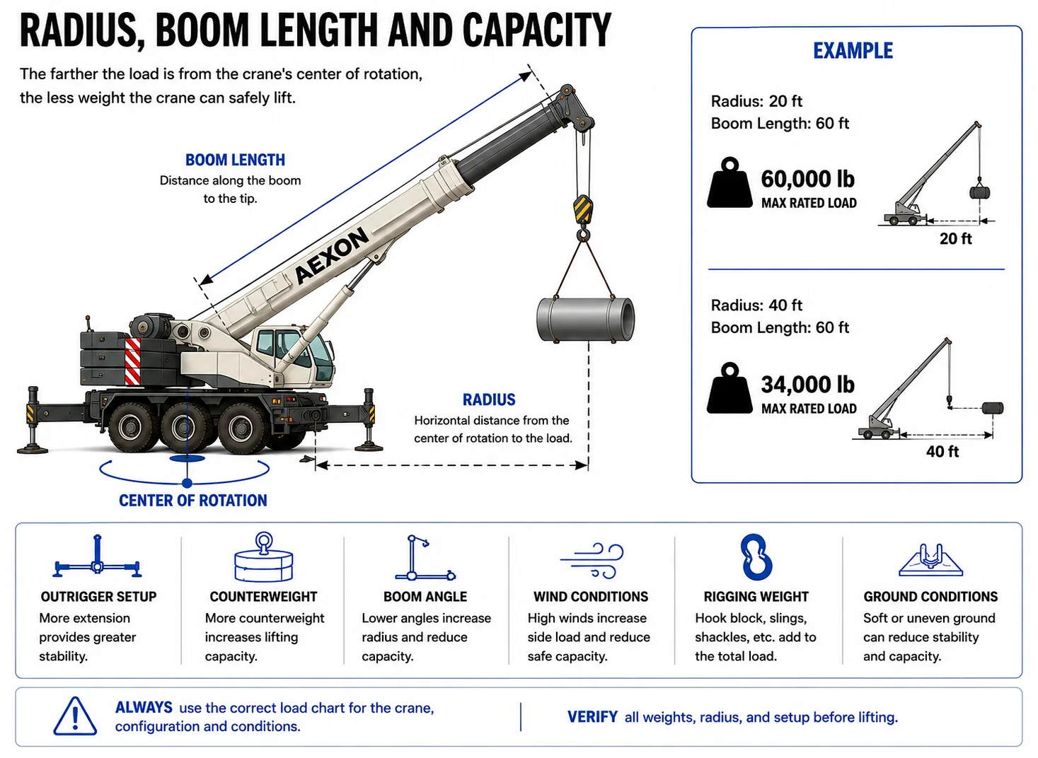
Because a crane does not have one lifting capacity.
Its allowable load changes with radius, boom length, boom angle, configuration, counterweight, outrigger setup and other conditions specified by the manufacturer.
That is why experienced operators and rigging crews don’t ask only:
“How much does it weigh?”
They also ask:
“What’s the radius?”
Understanding that relationship is one of the foundations of crane and rigging work.
What Is a Crane Load Chart?
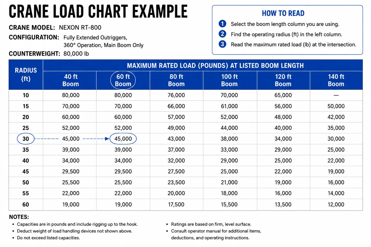
A crane load chart is the manufacturer’s table of rated lifting capacities for a specific crane and configuration.
It tells the qualified person how much the crane is rated to handle under the conditions represented by the chart.
A load chart may account for variables including:
- Operating radius
- Boom length
- Boom angle
- Outrigger position
- Counterweight configuration
- Jib or extension configuration
- Parts of line
- Operating area
- Attachments and deductions
The chart belongs to a specific crane model and configuration.
You cannot take the capacity from one crane’s chart and apply it to another crane that merely looks similar.
For crews working refinery outages and heavy industrial projects, load charts become especially important during the critical lifts and lift planning commonly encountered during turnarounds. Næxon’s Refinery Turnaround Dictionary: 100 Shutdown & Maintenance Terms also covers common terms such as critical lift, lift plan, rigging and crane spotter.
The Three Numbers You Need to Understand First
Before getting buried in a large load chart, understand three basic variables:
1. Load Radius
How far the load is horizontally from the crane’s center of rotation, as defined by the manufacturer’s chart.
2. Boom Length
The length/configuration of the boom being used.
3. Rated Capacity
The maximum load permitted by the applicable chart entry after all required conditions, notes and deductions are accounted for.
These three variables are closely connected.
Change one, and the available capacity may change dramatically.
What Is Load Radius?
Load radius is one of the most important concepts in crane operation.
In simplified terms, it is the horizontal distance from the crane’s axis of rotation to the vertical line through the load, measured according to the manufacturer’s definition.
Think of the crane from the side:
Crane center → horizontal distance → load
That horizontal distance is the operating radius.
Suppose a load is being handled at:
20 ft radius
Moving that same load farther away might increase the radius to:
30 ft
Nothing about the load itself changed.
It weighs exactly the same.
But the crane’s ability to handle it may have changed significantly.
Why Radius Changes Capacity
Think about using a wrench.
If you apply force near the bolt, the leverage is relatively small.
Apply the same force at the end of a long wrench and the turning effect becomes much greater.
A crane experiences a similar basic relationship.
A useful simplified concept is:
Load Moment ≈ Load × Radius
For example, ignoring the many additional factors involved in an actual crane rating:
10,000 lb × 10 ft = 100,000 lb-ft
Move the same load to 30 ft:
10,000 lb × 30 ft = 300,000 lb-ft
The load didn’t become heavier.
But its overturning effect relative to the crane increased dramatically.
This is why:
Radius can matter just as much as weight.
The Most Dangerous Assumption: “The Crane Can Pick 100 Tons”
Someone might say:
“That’s a 100-ton crane. The load is only 20 tons.”
That statement by itself tells you almost nothing about whether the planned lift is within rated capacity.
The crane may have a high maximum nominal capacity under a specific configuration and relatively short radius.
But the load may need to be placed:
80 feet away
with a particular boom configuration.
Available capacity at that operating condition can be far lower.
The correct question isn’t:
How big is the crane?
It is:
What does the applicable load chart allow at the planned configuration and radius?
Boom Length
Boom length is another major input.
Telescopic cranes can extend their booms to reach farther and higher.
A simplified load chart might contain boom lengths such as:
Radius
40-ft Boom
60-ft Boom
80-ft Boom
20 ft
Capacity A
Capacity B
—
30 ft
Capacity C
Capacity D
Capacity E
40 ft
—
Capacity F
Capacity G
These are intentionally shown as placeholders rather than lifting values.
Never use a teaching example as a working load chart.
The actual manufacturer’s chart must be used for the crane involved.
Why a Longer Boom Does Not Mean More Capacity
This catches beginners.
A longer boom gives the crane greater reach.
It does not automatically give the crane greater lifting capacity.
Extending the boom changes the geometry and forces acting on the crane.
Depending on the crane and configuration, a longer boom may have considerably less available capacity at a given operating condition.
So:
More reach ≠ more lifting capacity.
Sometimes the opposite is true.
Boom Angle
Boom angle is the angle of the boom relative to the manufacturer’s reference.
Generally, a boom raised more vertically produces a shorter horizontal reach than the same boom lowered outward.
As the boom lowers:
Radius generally increases.
As radius increases:
Rated capacity commonly decreases.
This creates an important relationship:
Lower boom → greater radius → potentially lower available capacity
But operators do not calculate capacity from that shortcut.
They use the manufacturer’s chart and crane’s rated-capacity information.
Radius Can Change During the Lift
This is where understanding the entire lift becomes important.
Suppose a crane picks a piece of equipment close to itself.
At the pickup point:
Radius = 25 ft
The crane then swings and places the equipment farther away.
At the set point:
Radius = 45 ft
The load weighs exactly the same throughout the lift.
But the crane may have considerably less rated capacity at 45 feet.
Therefore, checking only the pickup condition is not enough.
The lift must remain within the applicable rated capacity throughout the planned movement.
The worst condition may occur near the final set.
Picking Is Only Half the Lift
Imagine removing an exchanger component during a refinery turnaround.
The crane initially takes the load close to the structure.
Then the operator must:
Boom down
Swing
Increase radius
and place the load onto a trailer.
The pickup might be comfortably within capacity.
The final placement may be the limiting condition.
Experienced crews think about the entire load path.
Reading the Load Chart
A load chart commonly requires you to identify several conditions before selecting a capacity.
A simplified process looks like this:
Step 1 — Identify crane configuration
Verify the correct manufacturer’s chart for the crane and setup.
Step 2 — Determine operating radius
Use the planned radius according to the manufacturer’s definition.
Step 3 — Determine boom length/configuration
Identify the boom required for the lift.
Step 4 — Locate the correct chart intersection
Find the applicable radius and boom configuration.
Step 5 — Read all chart notes
This is critical.
Step 6 — Account for required deductions
The chart and manufacturer’s instructions determine what must be deducted.
Step 7 — Compare the allowable load with the actual lifted load
The planned condition must remain within the crane’s rated capacity and all applicable requirements.
The Fine Print Matters
A load chart isn’t just the big table of numbers.
The notes surrounding that table are part of the chart.
They may define requirements involving:
Outriggers
Counterweight
Boom configuration
Jib
Operating areas
Attachments
Wind limitations
Parts of line
Load handling equipment
Structural versus stability limitations
and other restrictions.
Ignoring the notes and reading only the capacity number can produce the wrong answer.
Outrigger Configuration
A crane’s capacity can depend heavily on how its outriggers are configured.
A manufacturer’s chart may contain different ratings for conditions such as:
Fully extended outriggers
Intermediate extension
Retracted outriggers
or other defined configurations.
You cannot use the fully extended-outrigger chart if the crane is configured differently.
The physical crane may be the same.
The rated configuration isn’t.
Over the Front, Side and Rear
Depending on the crane, capacity may also vary according to the operating area.
The manufacturer may define different ratings for lifting:
Over the side
Over the rear
Over the front
or within specifically defined working areas.
This relates to the crane’s structural configuration and stability.
Again, the chart for that exact machine determines the allowable operation.
Counterweight Matters
Counterweight helps the crane resist the overturning effect of the load.
Some cranes can operate with different counterweight packages.
The load chart must correspond to the counterweight actually installed.
You cannot read the capacity associated with:
Full counterweight
if the crane isn’t configured that way.
Configuration must match the chart.
Gross Load vs. Payload
Another common mistake is thinking only about the object being lifted.
Suppose the piece itself weighs:
20,000 lb
That doesn’t automatically mean the crane is handling only 20,000 pounds for chart purposes.
Depending on the manufacturer’s chart and instructions, the lifted load may need to account for items such as:
Hook block
Headache ball
Slings
Shackles
Spreader beam
Lifting beam
Other rigging
and certain crane attachments.
The load chart’s instructions determine the applicable deductions and load accounting.
Example: Why Rigging Weight Matters
Suppose the lifted object weighs:
40,000 lb
The complete rigging arrangement adds:
3,000 lb
If applicable under the chart’s instructions, the crane may effectively need to be evaluated for:
43,000 lb
rather than simply 40,000 lb.
On a lift operating near chart capacity, several thousand pounds of rigging can make a major difference.
This is why rigging should never be treated as weightless.
Parts of Line
The number of wire-rope parts supporting the hook block can also limit the allowable lifted load.
Even if the crane structure has sufficient capacity at a particular radius, the hoist system must also be configured appropriately.
Think of it as two separate questions:
Can the crane handle the load at this radius?
and:
Can the hoist/reeving arrangement handle the load?
Both must be satisfied.
What Happens Between Chart Values?
Suppose the chart lists:
40 ft radius
and:
45 ft radius
but your calculated operating radius is:
42 ft
Do not simply invent a capacity halfway between the two values.
Manufacturer instructions govern how intermediate values are handled. Commonly, the more conservative applicable chart value is required rather than interpolation unless the manufacturer specifically permits another method.
The chart instructions are the authority.
Never Round Radius in Your Favor
Suppose your actual radius is:
41 ft
and the chart has entries at:
40 ft
and:
45 ft
Using 40 ft because it’s “close enough” can result in using a higher capacity than permitted.
When dealing with crane capacity, assumptions should never be made in the direction that artificially increases allowable capacity.
What Is Capacity Percentage?
Crews sometimes discuss a lift as a percentage of chart capacity.
A simplified calculation is:
Lift Percentage = Calculated Load ÷ Applicable Rated Capacity × 100
For example:
If the applicable rated capacity after proper interpretation is:
50,000 lb
and the applicable lifted load is:
35,000 lb
then:
35,000 ÷ 50,000 × 100 = 70%
The lift is at approximately:
70% of that rated capacity.
Whether that triggers special planning requirements depends on the employer, facility, applicable regulations and lift procedure.
What Makes a Critical Lift?
There isn’t one universal percentage that defines every critical lift in every industrial facility.
A company’s critical-lift procedure may consider factors such as:
Percentage of crane capacity
Multiple-crane lifts
Personnel lifting
Loads over operating equipment
Extremely valuable equipment
Hazardous areas
Unusual rigging
Limited clearance
Complex load paths
Consequences of failure
The site’s lift procedure determines when additional engineering, approvals or planning are required.
This is why the term critical lift should always be interpreted according to the governing project or facility procedure.
Ground Conditions Matter Too
A load chart doesn’t make poor ground disappear.
Crane setup also requires consideration of the supporting surface and the forces transferred through:
Outriggers
Tracks
Tires
Mats
or other support arrangements.
A crane can be within chart capacity and still have a serious stability problem if the supporting ground or structure is inadequate.
Underground conditions may also matter.
Possible concerns can include:
Vaults
Buried piping
Sewers
Recently excavated areas
Soft fill
Underground structures
This is why crane setup is a planned activity—not simply finding a flat-looking place to park.
Level Matters
Load charts are based on manufacturer-defined conditions, which include crane setup requirements.
An out-of-level crane changes the geometry and loading.
That can affect stability and capacity.
The operator must set up and operate the crane according to the manufacturer’s requirements.
“Looks level from here” isn’t a load-chart calculation.
Wind Matters
Large loads can act like sails.
Examples include:
Vessel shells
Large duct sections
Structural panels
Roof sections
Long pipe spools
Preassembled modules
A relatively light object can present a huge surface area to the wind.
Wind can create:
Side loading
Load swing
Rotation
Control problems
and additional forces on the crane.
Manufacturer limits and the lift plan must be followed.
Load Weight Must Be Reliable
Every capacity calculation depends on knowing what you’re actually lifting.
Possible weight sources include:
Certified weight documentation
Engineering drawings
Manufacturer data
Shipping documents
Calculated weights
or other approved information.
Guessing:
“It’s probably around 15 tons”
isn’t enough for lift planning.
And old equipment can contain surprises.
A vessel or exchanger may contain:
Residual liquid
Sludge
Scale
Catalyst
Internal components
or other material that changes the actual lifted weight.
Center of Gravity Changes the Lift
Total weight is only part of the problem.
You also need to understand where that weight acts.
The load’s:
Center of gravity
determines how the load hangs and how the rigging shares the force.
An off-center piece may tilt as it leaves its support.
One sling may take substantially more load than another.
A spreader beam may be required.
The hook needs to be positioned appropriately relative to the center of gravity for the planned lift.
This is where crane planning and rigging knowledge come together.
Sling Angle Still Matters
The crane chart tells you what the crane can handle.
It doesn’t eliminate the need to correctly evaluate the rigging.
As sling angles become flatter, sling tension increases.
So the crew must verify both:
Crane capacity
and:
Rigging capacity
A crane capable of lifting the load does not make undersized slings, shackles or lifting points acceptable.
The Crane Operator and Rigger See Different Parts of the Same Lift
The operator is focused on:
Crane configuration
Radius
Boom
Capacity
Operating area
Machine condition
The qualified rigging personnel may also be focused on:
Load weight
Center of gravity
Sling configuration
Shackles
Lifting points
Tag lines
Load control
The signal person focuses on maintaining clear communication with the operator.
These roles overlap around one objective:
Move the load within the planned limits without losing control of it.
Example: Reading a Lift From Start to Finish
Imagine a heat-exchanger bundle is being removed during a turnaround.
The load information establishes a lifted weight of:
30,000 lb
The rigging arrangement adds additional weight that must be accounted for according to the crane manufacturer’s instructions.
The lift starts at:
25 ft radius
but the trailer placement requires:
45 ft radius
The boom configuration remains suitable for both positions.
The wrong approach would be:
“The crane easily handles it at 25 feet, so we’re good.”
The correct approach is to evaluate the crane throughout the planned load path, including the more demanding 45-ft condition.
If the applicable chart capacity becomes limiting at the final radius, that’s the condition that controls the lift.
Another Example: The Load Gets “Heavier” Without Gaining a Pound
Picture a 10,000-lb spool.
At the pickup point:
Radius = 15 ft
Simplified moment:
10,000 × 15 = 150,000 lb-ft
At the set point:
Radius = 40 ft
Simplified moment:
10,000 × 40 = 400,000 lb-ft
The spool still weighs:
10,000 lb
But its leverage relative to the crane has increased dramatically.
That’s why old hands pay so much attention to radius.
What Load Charts Do NOT Tell You by Themselves
A load chart does not replace a complete lift plan.
It does not automatically tell you that:
The ground is adequate
The rigging is correct
The lifting points are rated
The load weight is accurate
The center of gravity is known
Wind conditions are acceptable
The load path is clear
Power-line clearances are adequate
Personnel are safely positioned
All of those issues still have to be addressed as applicable.
The Biggest Load-Chart Mistakes
Most load-chart errors come from misunderstanding one of a few basic conditions.
Watch for:
Wrong radius
Wrong boom length
Wrong crane configuration
Wrong outrigger chart
Wrong counterweight
Ignoring rigging or required deductions
Wrong operating area
Incorrect load weight
Ignoring chart notes
Assuming capacity between chart values
Checking only the pickup point
That last one deserves emphasis.
The crane must be suitable for the entire planned lift—not merely the moment the load leaves the ground.
A Better Way to Think About Crane Capacity
Instead of asking:
“Can this crane lift 40,000 pounds?”
ask:
“Can this crane, in this exact configuration, lift this total calculated load throughout this entire planned radius and load path under the manufacturer’s requirements?”
That is a much better question.
A Simple Field Learning Sequence
When you’re studying a load chart with a qualified operator or trainer, work through it in this order:
1. Confirm the crane model.
2. Confirm crane configuration.
3. Confirm counterweight.
4. Confirm outrigger or carrier configuration.
5. Determine boom configuration.
6. Determine maximum planned radius.
7. Find the applicable chart.
8. Read every relevant note.
9. Determine applicable rated capacity.
10. Account for all required load and deductions.
11. Verify hoist/reeving limitations.
12. Evaluate the entire lift path.
This sequence turns the load chart from a wall of numbers into a logical process.
Why Experienced Hands Respect Radius
Crane work can look effortless from the ground.
The operator moves a lever.
The boom swings.
A 30,000-pound piece floats across the jobsite.
But behind that movement is geometry, machine configuration, structural limits, stability, rigging, communication and planning.
And one of the most important numbers in that entire process is often just:
Radius.
A few extra feet can change the allowable capacity.
That’s why “just boom down a little farther” is not a casual request when a crane is handling a significant load.
Load Charts Are Limits, Not Targets
The numbers on the chart aren’t goals.
They’re operating limits under the conditions defined by the manufacturer.
The objective isn’t to see how close a crew can get to the edge of the chart.
The objective is to plan and execute the lift within the applicable limits and procedures.
Industrial sites may impose additional restrictions beyond the manufacturer’s rated capacities.
Those requirements matter too.
The Bottom Line
To understand a crane load chart, start with three things:
Radius
How far horizontally the load acts from the crane’s center of rotation under the manufacturer’s definition.
Boom Length
The boom configuration required to reach and place the load.
Capacity
What the manufacturer’s applicable chart allows at that exact operating condition.
Then add everything else:
Configuration. Counterweight. Outriggers. Operating area. Rigging weight. Reeving. Ground conditions. Wind. Load weight. Center of gravity. Chart notes.
A crane’s capacity is never simply the number painted on the side of the machine.
The real answer is found in the load chart.
And the load chart only gives the right answer when you give it the right conditions.
Continue Learning
Crane capacity is only one side of a safe lift. The next skills to understand are sling angles, center of gravity, rigging hardware, load control and lift planning.
For workers moving into shutdown and turnaround work, Næxon’s Refinery Turnaround Dictionary is a useful reference for the terminology crews use around critical lifts, lift plans and rigging. You can also explore the broader Næxon Resources & Learning content for industrial trade education and jobsite knowledge.
Important: This article is educational and does not replace the crane manufacturer’s load chart, operating manual, engineered lift plan, qualified operator/rigger training, employer procedures, or applicable regulations. Always use the documentation and requirements for the actual crane and lift.


