Learning Center: Riggers • Math • Intermediate
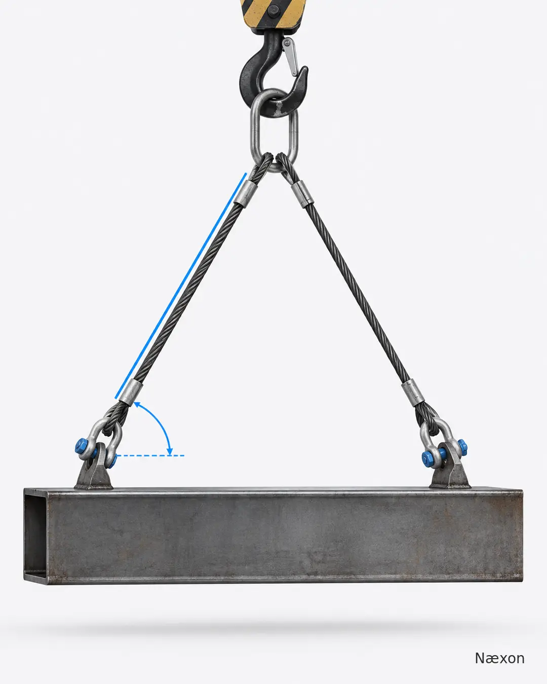
The load is ready, the pick points are fixed, and nobody has a protractor in hand. A rigger can still estimate the tension in each leg of a symmetrical two-leg bridle by measuring two things that are already part of the rigging triangle: the loaded sling length and the vertical rise from the pick-point level to the hook or master-link connection.
This method is useful because the sling angle is not just a drawing detail. As the bridle gets flatter, each leg must pull harder to provide the same vertical support. The calculation below helps a trained crew understand that effect, compare a proposed arrangement with the lift plan, and recognize when the geometry needs qualified review. It does not approve a lift or replace the sling manufacturer’s rated-load information, the rigging plan, or the judgment of a qualified person.
The geometry behind the method
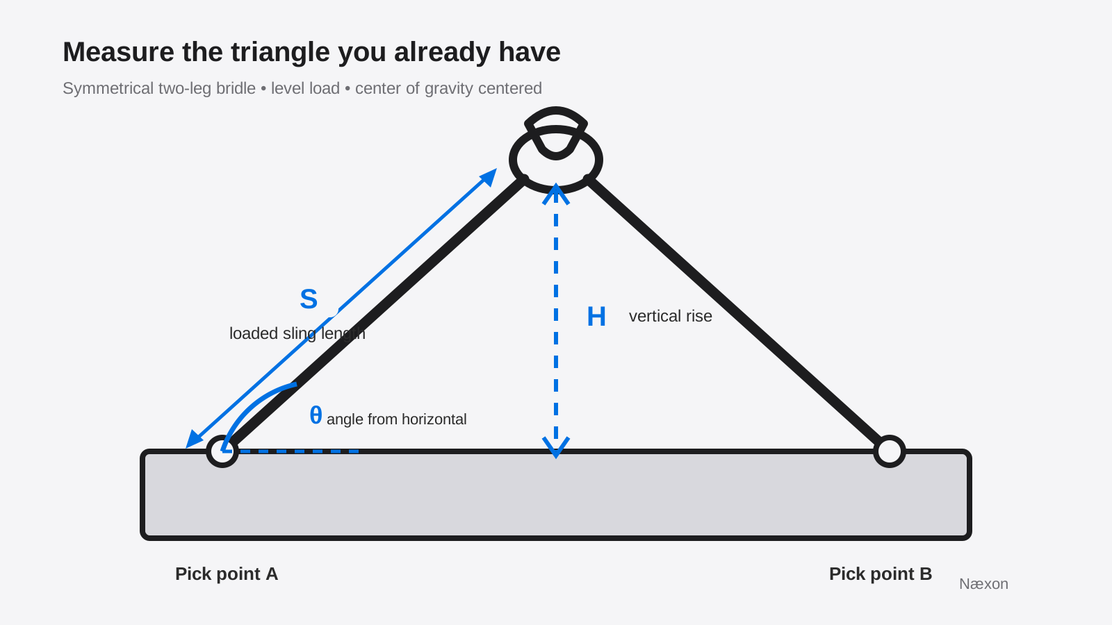
For a level load with its center of gravity centered between two equal pick points, each loaded leg supports one-half of the load vertically. The actual force along each sling leg is higher than that vertical share unless the leg is vertical. The ratio between the loaded sling length and the vertical rise supplies the angle factor.
Use W for total load weight, n for the number of legs assumed to carry the load, S for loaded sling length, H for vertical rise, and T for tension in one loaded leg. Keep S and H in the same unit. Feet divided by feet or inches divided by inches produces the same unitless factor.
T = (W ÷ n) × (S ÷ H)
In a basic symmetrical two-leg example, n equals 2. The first term, W ÷ n, is the vertical share carried by each leg. The second term, S ÷ H, is the load-angle factor. Because a sloping sling is always longer than its vertical rise, the factor is always 1.00 or greater.
Why a flatter bridle increases tension
Imagine moving the hook upward while the pick points stay fixed. The slings become steeper, H increases relative to S, and the ratio S ÷ H moves closer to 1.00. Move the hook down and the bridle becomes flatter. H becomes a smaller portion of S, so the angle factor and the force in each leg increase.
This is why dividing the load weight by two is not a complete sling-tension calculation. Half the load is only the vertical share. It ignores the extra force created by the sloping geometry. A correct calculation must include the angle factor or an equivalent trigonometric method.
The horizontal angle is measured between the sling leg and a horizontal line through the pick point. Do not confuse it with the angle from vertical or the included angle between both sling legs. Mixing those angle definitions is a common source of dangerous errors. For the measurement method, the angle does not need to be measured directly because H ÷ S equals the sine of the horizontal angle.
Worked example
Assume a verified 8,400-pound load is level, the center of gravity is centered, two identical sling legs are equally loaded, each loaded leg measures 10 feet from its pick point to the common upper connection, and the vertical rise is 8 feet. These assumptions matter. If the load is not symmetrical or the center of gravity is offset, the two legs may not share the load equally.
First calculate the vertical share: 8,400 lb ÷ 2 = 4,200 lb per leg. Then calculate the angle factor: 10 ft ÷ 8 ft = 1.25. Finally multiply the values: 4,200 lb × 1.25 = 5,250 lb of tension in each leg.
An independent trigonometric check gives the same result. H ÷ S = 8 ÷ 10 = 0.80, so the horizontal sling angle is approximately 53.1 degrees. Then T = W ÷ (2 × sin 53.1°) = 8,400 ÷ 1.60 = 5,250 lb per leg. The two methods agree.
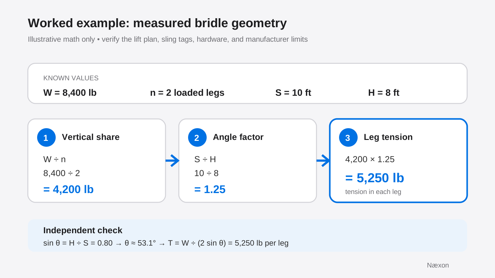
The result is the force used to evaluate each sling leg in this simplified example. It is not the weight of the load and it is not automatically the required sling rating. Selection must still account for the sling tag, hitch configuration, material, fittings, D/d effects where applicable, edge protection, temperature and chemical exposure, and every requirement in the approved lift plan and manufacturer instructions.
A practical field sequence
- Confirm the load. Use an approved weight source. Include lifting attachments, spreaders, rigging below the hook, retained contents, and anything else the lift plan requires. Do not guess from appearance.
- Confirm the load model. This lesson assumes a level, symmetrical load with the center of gravity midway between equal pick points and two legs carrying the load. Stop if the geometry or load distribution does not match.
- Identify the loaded legs. Do not assume three or four legs share load equally. Use the leg count and load distribution required by the lift plan or qualified person.
- Measure S and H. Measure S along the loaded sling from the load connection to the common upper connection. Measure H vertically from the pick-point elevation to that upper connection. Use the same units for both.
- Calculate and record. Find W ÷ n, find S ÷ H, and multiply. Write the assumptions beside the result so another qualified reviewer can reproduce it.
- Check another way. If possible, calculate the horizontal angle from sin θ = H ÷ S and verify T = W ÷ (n × sin θ). A drawing, approved rigging calculator, or second qualified person can provide another check.
- Compare with the controlling information. Verify the complete assembly against sling identifications, manufacturer tables, hardware limits, hitch reductions, the lift plan, and site rules before the load is tensioned.
Where the simple calculation stops
The method is not valid as a stand-alone answer for an off-center center of gravity, unequal leg lengths, unequal pick-point elevations, a load that will tilt, a bridle with legs at different angles, dynamic loading, side loading, or any arrangement in which two legs do not share the vertical load equally. Those conditions require a load-distribution analysis by a qualified person.
A tag showing a multi-leg assembly rating also does not eliminate the need to understand the angle on which that rating is based. For angles not shown in the applicable rated-load information, use the next lower listed angle or obtain the calculation required by the manufacturer, site procedure, or qualified person. Horizontal sling angles below 30 degrees should not be used unless specifically allowed by the sling manufacturer or a qualified person.
Troubleshooting the numbers
If the calculation produces a factor below 1.00, S and H were probably reversed or one dimension was measured from the wrong points. A sling cannot be shorter than its vertical projection. Recheck the measurement path and units.
If the two legs have different S or H values, do not average them and call the load symmetrical. The mismatch may indicate unequal geometry, a shifted hook, different pick elevations, or an off-center center of gravity. Stop and have the arrangement reviewed.
If the load tips during a controlled test lift, the assumed center of gravity or load sharing was wrong, or the hook is not vertically above the combined center of gravity. Land the load when it is safe to do so and revise the plan. Do not try to solve unexpected tilt by moving under the load, side-pulling, or improvising sling adjustments.
If a calculated leg tension is close to a stated limit, that is not permission to proceed. Confirm every reduction and component limit with the controlling documentation. The lowest-rated relevant component or condition governs the assembly.
Common mistakes
The most common error is using W ÷ 2 as the final answer. Other errors include measuring the straight horizontal half-span instead of the sling length, using the hook height above the floor instead of the vertical rise above the pick points, mixing feet and inches, confusing horizontal angle with angle from vertical, assuming every leg in a multi-leg bridle shares equally, and calculating from an estimated load weight.
Another mistake is treating a clean calculation as proof that the lift is acceptable. The formula models one part of the problem: static tension in idealized loaded legs. It does not inspect the sling, protect an edge, center a hook, verify a shackle, control the load, or authorize the lift.
Field Rules
- Know the load weight and center of gravity before calculating.
- State the angle reference; this lesson uses angle from horizontal.
- Use the same units for S and H.
- Calculate only with a load-sharing model that matches the actual lift.
- Check the result independently and follow the approved lift plan.
- Stop when geometry, hardware, sling condition, or load behavior differs from the plan.
Knowledge Check
- What does W ÷ n represent in this method?
- Why must S and H use the same units?
- For an ideal two-leg symmetrical bridle, what happens to leg tension when H decreases but S and W remain fixed?
- Can this formula alone approve a lift with an off-center center of gravity?
- What does a calculated angle factor below 1.00 usually indicate?
Answers
- It is the assumed vertical share carried by each loaded leg.
- The units must cancel so S ÷ H becomes a unitless angle factor.
- The S ÷ H factor increases, so tension in each leg increases.
- No. Unequal load distribution needs analysis under the lift plan by a qualified person.
- The dimensions were likely reversed, mixed, or measured from incorrect points because sling length cannot be less than its vertical projection.
Practical Exercise
On paper, sketch a level 6,000-pound load supported by two equal sling legs. Use S = 12 ft and H = 9 ft. Label W, n, S, H, and T. Calculate the tension per leg, then check it by finding sin θ = H ÷ S.
Expected result: W ÷ n = 3,000 lb. S ÷ H = 12 ÷ 9 = 1.333. T = 3,000 × 1.333 ≈ 4,000 lb per leg. The check is sin θ = 0.75, so T = 6,000 ÷ (2 × 0.75) = 4,000 lb per leg. This is a training calculation, not an approved lift plan.
Related learning
Review how sling angle changes the load on rigging for the core concept, then use field formulas for riggers to extend the math. Before assuming equal load share, study why a load tilts when its center of gravity is missed. If the load behaves unexpectedly, review what riggers check when a suspended load starts rotating. For arithmetic and trigonometric checks, open the Næxon Numerus calculator.