Evening Edition • Primary trade: QC Inspectors • Skill level: Intermediate • Classification: Field Skill • Estimated reading time: 10 minutes
What you’ll learn: how to establish a trustworthy reference surface, measure groove-weld reinforcement and undercut with a bridge cam gauge, recognize false readings, and document the result without turning a measurement into an unauthorized acceptance decision.
A weld can look high, low, smooth, or sharp under a flashlight, but appearance alone does not tell the inspector how far a feature extends from the parent-metal surface. That is where a bridge cam gauge becomes useful. It spans the weld, references the surrounding base metal, and lets a movable probe compare the weld feature with that datum.
The difficult part is not moving the pointer. It is making sure the gauge is measuring the intended feature from the correct reference. A grain of spatter under one foot, a tilted bridge, a probe beside the highest point, or a reading taken from scale parallax can create a convincing number that is still wrong.
What the gauge can—and cannot—decide
A bridge cam gauge is a multi-function visual inspection tool. Depending on the model and scale, it can be used for weld reinforcement, undercut or pit depth, outside misalignment, preparation angle, and fillet-weld dimensions. This lesson deliberately focuses on two related tasks: reinforcement above adjacent parent metal and undercut below the original parent-metal surface.
The gauge produces a dimensional observation. It does not decide by itself whether the weld is acceptable. Acceptance comes from the governing drawing, weld procedure, fabrication specification, construction code, inspection plan, or other approved project requirement. The inspector must identify that requirement before assigning a disposition.
“Discontinuity” and “defect” are therefore not interchangeable. A discontinuity is an interruption in the expected weld profile or material. It becomes a rejectable defect only when it exceeds the applicable acceptance criteria. The gauge supplies evidence; the controlling document supplies the limit.
The reference surface controls the reading
For reinforcement, both feet of the gauge must sit squarely on clean parent metal on opposite sides of the weld. The probe is lowered to the highest point of the weld crown. The vertical difference between the parent-metal datum and that point is the reinforcement reading.
Clean does not mean aggressively grinding the inspection surface until it changes. It means removing loose slag, spatter, dirt, or other removable interference by an approved method while preserving the weld and base-metal profile. The gauge itself should be clean, undamaged, legible, and controlled under the site’s tool or calibration program. Follow the gauge manufacturer’s instructions and the project procedure.
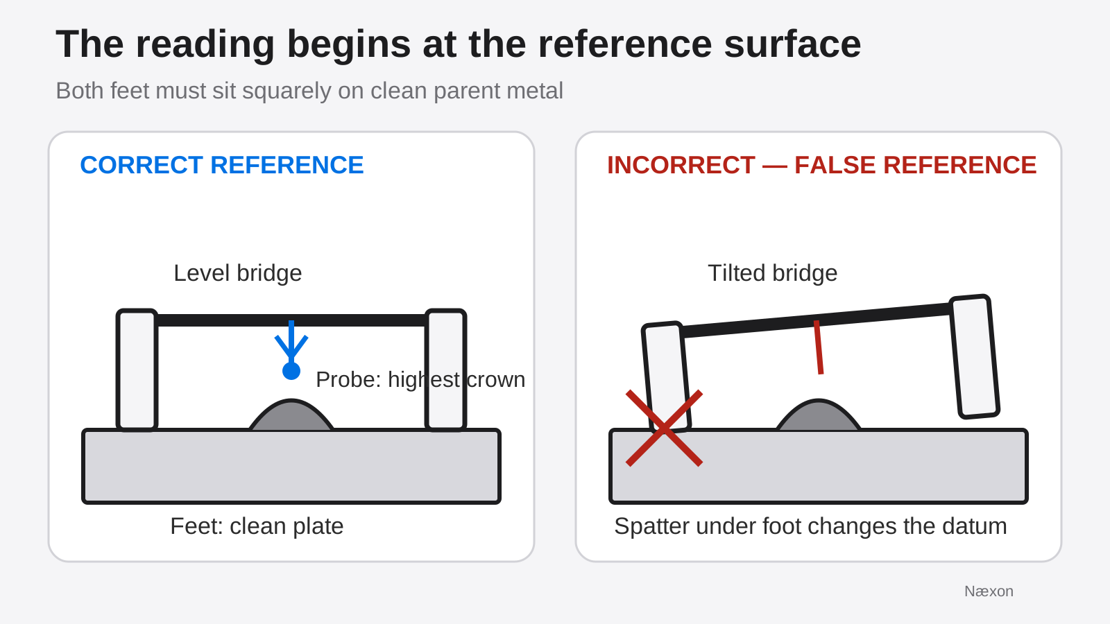
The incorrect setup in Figure 1 fails because one foot no longer represents the original parent-metal surface. The gauge rotates around the interference, changing the relationship between its body, probe, and weld. A false high or false low reading can result depending on the direction of the tilt. The warning sign is daylight, rocking, unequal foot contact, or a reading that changes when the gauge is reseated.
Measuring weld reinforcement
Before approaching the weld, confirm that hot work has stopped, the area is safe to enter, and the work is cool enough for the instrument and the required inspection method. Keep eye protection in place; raised welding hoods do not replace primary eye protection where flying slag, wire-brush debris, or grinding particles remain possible.
- Identify the inspection location. Use the weld map, joint number, drawing, or inspection plan so the observation can be traced to the correct weld.
- Prepare the reference areas. Verify that both gauge feet will contact sound, clean parent metal rather than spatter, scale, a nearby tack, a coating ridge, or another weld.
- Seat the bridge. Place the gauge squarely across the weld. Check for rocking and visible gaps beneath either foot.
- Find the highest crown. Lower the probe until it just contacts the highest point. Do not force the probe into soft contamination or drag it in a way that damages the tip.
- Read the correct scale. Confirm inch or metric units, view the scale squarely to reduce parallax, and record the displayed increment rather than estimating extra precision.
- Repeat the setup. Lift and reseat the gauge. If access permits, approach from the opposite side. A meaningful difference between repeat readings is a reason to investigate the setup, surface, or instrument.
The inspector should sample the locations required by the governing plan rather than measuring only the easiest point. If the bead profile varies, the highest measured reinforcement within the required inspection area is normally the value that matters for comparison, subject to the controlling procedure.
Measuring undercut depth
Undercut is a groove melted into the parent metal next to the weld toe and left unfilled by weld metal. The bridge again references the original parent-metal surface, but the probe moves downward into the groove instead of upward to the crown. The measurement is the vertical depth from the parent-metal datum to the deepest point reached by the probe.
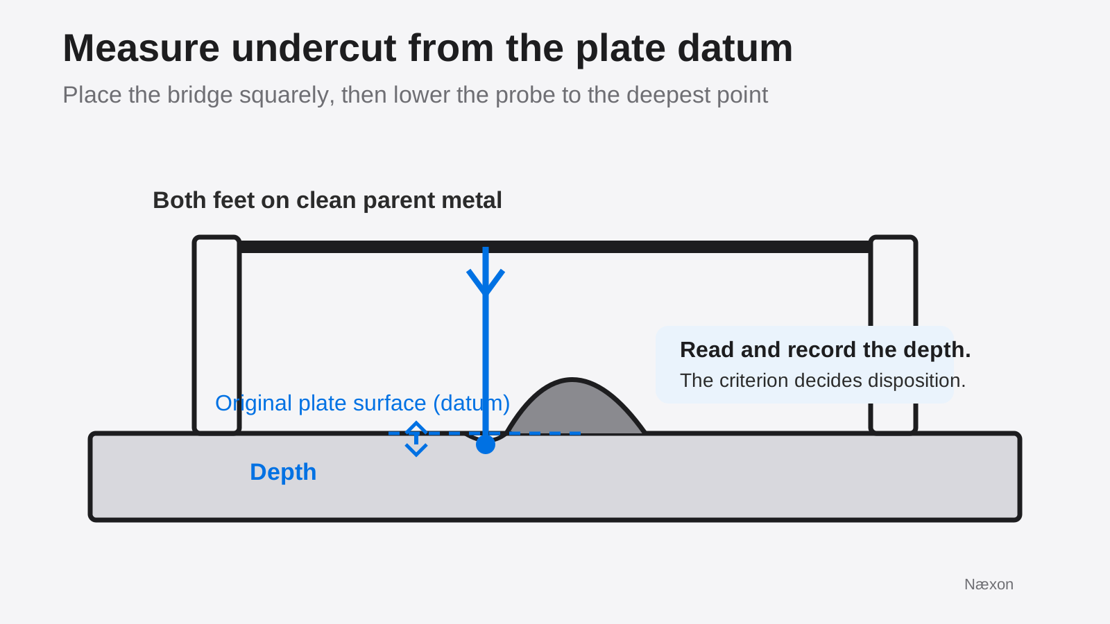
Do not place a foot inside the groove or on the weld crown. Do not measure a rounded transition as undercut simply because a shadow makes it look deep. Use adequate light, clean the toe without changing its profile, and confirm the probe is actually seated at the deepest point. Measure the length or distribution of the indication separately when the governing criteria require it; depth alone may not be the only variable.
Worked inspection example
Consider a training coupon with three marked stations: A, B, and C. For this exercise only, the mock inspection instruction states a maximum reinforcement of 3.0 mm and a maximum undercut depth of 0.5 mm. These are illustrative limits created for the exercise, not universal acceptance criteria and not permission to evaluate production work without the governing documents.
At Station A, the repeated reinforcement readings are 2.6 mm and 2.6 mm, while the undercut reading is 0.2 mm. At Station B, reinforcement reads 3.4 mm after the gauge is reseated and confirmed level, while undercut is 0.2 mm. At Station C, reinforcement is 2.8 mm and undercut is 0.7 mm at the deepest verified point.
Station A meets both mock limits. Station B is placed on hold because the measured reinforcement is 0.4 mm above the exercise limit: 3.4 mm − 3.0 mm = 0.4 mm. Station C is placed on hold because the measured undercut is 0.2 mm above the exercise limit: 0.7 mm − 0.5 mm = 0.2 mm. The inspector records the actual measurements and location rather than writing only “fail.”
The independent check is repeatability. Reseating the gauge at Station B produced the same 3.4 mm reading, and the feet remained flush on clean parent metal. The reasonableness check is profile-based: the probe visibly contacts the local high point or groove while both feet remain on the plate datum. If a reading changes greatly when the tool is reseated, it is not yet reliable enough for disposition.
Do not round a borderline value in the direction of acceptance. Record only the precision supported by the gauge scale and follow the project procedure for readings at or near a limit, instrument uncertainty, reinspection, or verification by another inspector.
Troubleshooting inconsistent readings
The gauge rocks. Look for spatter, slag, surface scale, a coating edge, distortion, or feet placed too close to the weld transition. Correct the reference condition using an approved method or select a valid nearby position allowed by the procedure.
The probe does not reach the deepest groove. The body may be oriented incorrectly, the feature may be too narrow for the probe, or access may be restricted. Do not force or modify the gauge. Use the approved alternate instrument or escalate the limitation.
The reading changes with viewing angle. This suggests parallax. View the pointer and scale squarely, use consistent lighting, and repeat the measurement.
The reading differs when approached from the other side. Recheck foot contact, the true local high or low point, weld curvature, and instrument condition. Record the required controlling value only after the cause is understood.
The scale or pointer is damaged. Remove the gauge from use under the site’s control process. A familiar tool is not automatically a trustworthy tool.
Common mistakes
The most common mistake is treating the bridge cam gauge like a stamp that turns every number into pass or fail. Other errors include measuring over spatter, confusing reinforcement with total weld thickness, placing the probe beside the maximum crown, using the wrong unit scale, reading at an angle, forcing the probe, estimating digits the scale cannot support, and failing to record the exact weld location.
Another mistake is evaluating undercut from depth alone when the governing criteria also consider length, accumulation, weld orientation, loading, or joint category. The inspector must read the entire applicable requirement, not isolate one convenient number.
Field Rules
- Find the governing acceptance criteria before assigning disposition.
- Use clean, stable parent metal as the datum.
- Confirm units and the correct scale before reading.
- Measure the actual high or low point, not the easiest point to reach.
- Reseat and repeat when a reading matters.
- Record the value, location, instrument identity when required, and applicable criterion.
- Stop and escalate when access, surface condition, instrument condition, or project requirements make the result uncertain.
Knowledge Check
- A gauge gives 3.2 mm with one foot resting on spatter. After the surface is properly cleared and the gauge is reseated, it reads 2.5 mm. Which reading is valid, and why?
- In the training example, which station is held for reinforcement and which is held for undercut?
- An inspector can see a groove at the weld toe, but the probe cannot reach its deepest point without tilting the bridge. What is the correct next step?
- Why is a dimensional reading not automatically a defect?
- Two repeat readings differ significantly. What should the inspector do before recording a disposition?
Answers
- The 2.5 mm reading is the valid setup result because both feet reference clean parent metal. The 3.2 mm value used a false datum created by spatter.
- Station B is held for reinforcement at 3.4 mm against the mock 3.0 mm limit. Station C is held for undercut at 0.7 mm against the mock 0.5 mm limit.
- Stop. Do not tilt, force, or modify the gauge. Use an approved alternate instrument or escalate the access limitation under the inspection procedure.
- The governing code, drawing, specification, or inspection plan defines when a measured discontinuity is rejectable. The gauge supplies the measurement only.
- Reseat the gauge, check reference contact, lighting, units, local high or low point, and instrument condition. Escalate if repeatability cannot be established.
Practical Exercise
Draw a groove-weld cross-section with parent metal on both sides. Mark one small piece of spatter under the left gauge foot, then sketch how that interference tilts the bridge. Next, redraw the gauge with both feet flat and the probe at the weld crown. Label the datum, probe contact, and measured reinforcement.
For a paper inspection record, use these illustrative measurements: Station 1 reinforcement 2.7 mm and undercut 0.3 mm; Station 2 reinforcement 3.1 mm and undercut 0.4 mm. Compare them with a mock maximum of 3.0 mm reinforcement and 0.5 mm undercut. The expected result is that Station 1 meets both mock limits, while Station 2 is held for reinforcement only. Your checking method is to repeat the comparison characteristic by characteristic and state the location and difference from the mock limit.
Related learning
Start with precision measurement fundamentals if you need practice with reference surfaces, repeatability, and reading scales. Review what causes weld undercut to connect the measured profile with likely welding variables. Continue to welding positions explained to understand how joint orientation changes access, travel, and inspection conditions.