
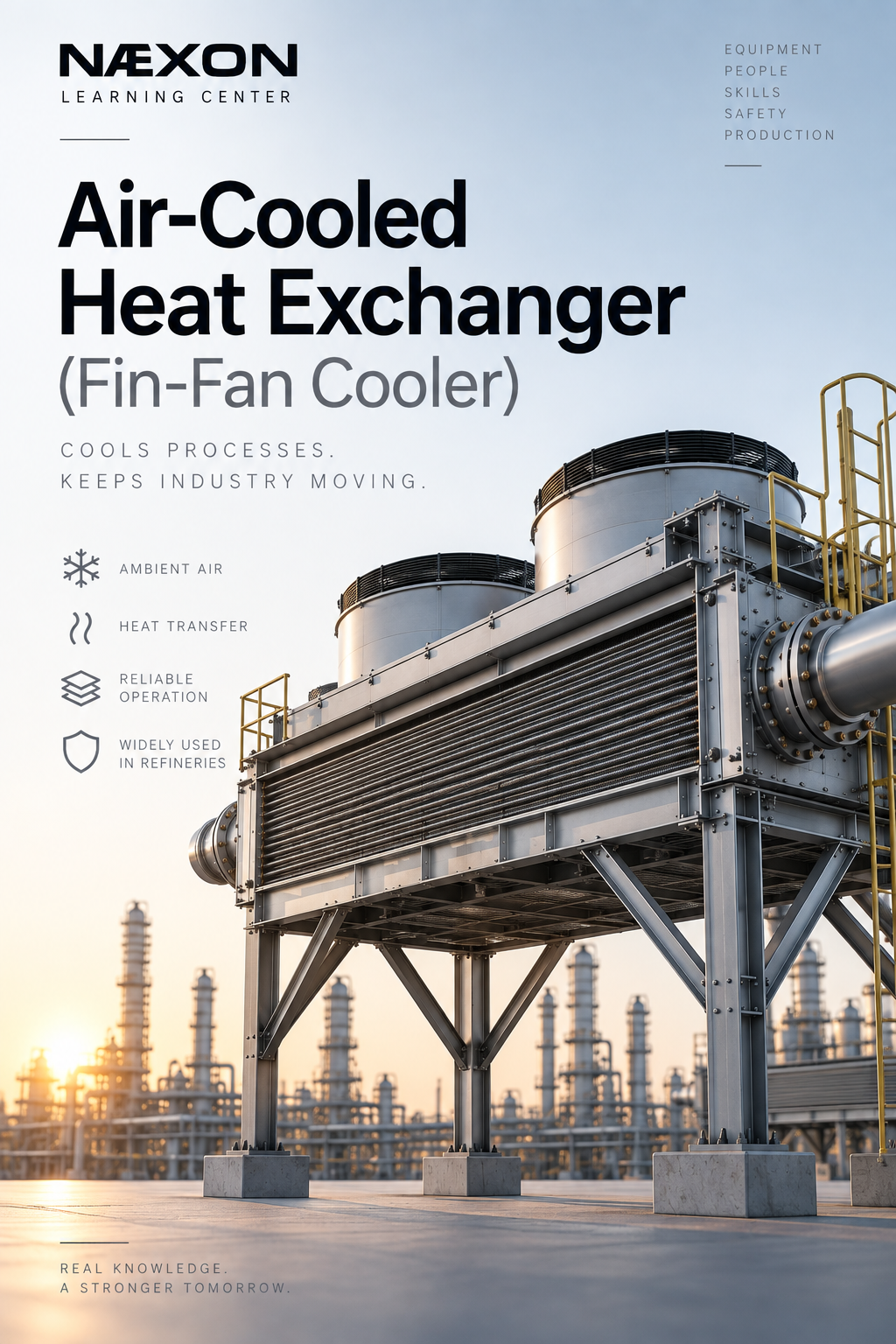
Walk through almost any refinery, petrochemical complex, gas-processing facility, or chemical plant and eventually you will see a large elevated structure filled with horizontal finned tubes and massive rotating fans. That equipment is an air-cooled heat exchanger, commonly called a fin fan, air cooler, or ACHE.
Air-cooled heat exchangers perform one of the most important jobs in a process plant: removing heat from a process stream without requiring cooling water.
The concept sounds simple. Hot process fluid travels through tubes while large fans move atmospheric air across the outside of those tubes. Heat moves from the process fluid through the tube wall and fins and into the surrounding air.
But the equipment itself can become surprisingly complex. Fan configuration, tube arrangement, fin condition, airflow, ambient temperature, process pressure, fouling, vibration, header design, and operating conditions can all affect performance.
For operators, pipefitters, welders, millwrights, inspectors, engineers, and maintenance crews, understanding how a fin fan works makes troubleshooting and field work considerably easier.
What Is an Air-Cooled Heat Exchanger?

Figure — Air-Cooled Heat Exchanger (Fin-Fan Cooler). Overview of forced- and induced-draft configurations, showing process flow, cooling-air direction, major components, and the basic heat-transfer process used to cool or condense refinery process streams.
An air-cooled heat exchanger is a heat-transfer device that uses ambient air as the cooling medium.
A hot process fluid flows inside tubes. Air flows across the outside of those tubes. Heat passes from the hotter process fluid through the tube wall and into the cooler atmospheric air.
The two fluids never intentionally mix.
Unlike a conventional shell-and-tube heat exchanger, which commonly transfers heat between two process or utility fluids, an air cooler normally transfers heat directly from a process stream into the atmosphere.
The basic heat-transfer path is:
Hot process fluid → tube wall → fins → moving air → atmosphere
The process fluid leaves the exchanger at a lower temperature.
Why Refineries Use Fin Fans
Refineries must remove enormous quantities of heat.
Process streams may leave furnaces, reactors, compressors, fractionation systems, or other equipment at temperatures far above what downstream equipment can tolerate.
That heat has to go somewhere.
Cooling water systems can remove large quantities of heat, but cooling water requires pumps, piping, cooling towers, chemical treatment, makeup water, and additional infrastructure.
Air cooling provides another option.
Fin fans are particularly useful because they can:
- Reduce demand on cooling-water systems.
- Conserve water.
- Eliminate direct cooling-water contact with process equipment.
- Handle large process flows.
- Operate continuously outdoors.
- Cool or condense hydrocarbon streams.
- Reduce process temperatures before downstream equipment.
- Provide relatively simple large-scale heat rejection.
Many refinery cooling systems therefore use combinations of air cooling and water cooling.
A process stream might first pass through an air cooler to remove the bulk of its heat and then enter another exchanger for additional cooling.
Where Fin Fans Are Found in a Refinery
Air-cooled heat exchangers can appear throughout a refinery.
Common applications include:
- Crude and vacuum units.
- Hydrocrackers.
- Hydrotreaters.
- Catalytic reformers.
- Fluid catalytic cracking units.
- Coker units.
- Compressor systems.
- Gas recovery systems.
- Fractionation systems.
- Sulfur recovery areas.
- Hydrogen plants.
- Product cooling systems.
They may cool liquid hydrocarbons, hydrocarbon vapors, compressed gases, lubricating oils, process water, or other process streams.
Some services use the exchanger primarily as a cooler.
Others use it as a condenser, where process vapor loses enough heat to partially or completely become liquid.
The Basic Flow Path
Imagine a hot process stream leaving a refinery unit.
The piping carries that stream to the inlet header of the air cooler.
From there:
Process piping → inlet nozzle → header → tubes → outlet header → outlet nozzle → downstream piping
While the process fluid moves through the tubes, fans move atmospheric air across the outside surface.
The air absorbs heat and exits warmer than when it entered.
The process fluid leaves cooler.
The two flow paths therefore look like this:
Process side:
Hot process → tubes → cooler process
Air side:
Cool atmospheric air → fan → finned tubes → warmer air
Understanding those two paths is fundamental to understanding the entire machine.
Why the Tubes Have Fins
One of the most noticeable differences between an air cooler and many other heat exchangers is the tube surface.
Fin-fan tubes are covered with thin metal fins.
Why?
Because air is relatively poor at transferring heat compared with liquids such as water.
To compensate, engineers dramatically increase the outside surface area of the tubes.
A plain tube has only its outside cylindrical surface available for heat transfer.
Adding hundreds of fins creates substantially more surface area.
More surface area allows more heat to transfer from the tube into the passing air.
This is why damaged, dirty, bent, or plugged fins can significantly reduce exchanger performance.
Major Components of a Fin Fan
Understanding the individual components makes the complete system easier to understand.
Tube Bundle
The tube bundle contains the finned tubes through which the process fluid travels.
A large air cooler may contain hundreds of tubes arranged in rows.
The tubes are supported by a structural frame and connected to headers at each end.
The bundle is essentially the heat-transfer core of the exchanger.
Finned Tubes
The process fluid flows inside these tubes.
Metal fins attached to the outside dramatically increase the available heat-transfer surface.
Fin construction varies depending on temperature, service, corrosion conditions, and exchanger design.
Damage to the fins can restrict airflow or reduce heat-transfer efficiency.
Headers
Headers distribute process fluid into and out of the tubes.
Depending on the exchanger design, headers may be fabricated boxes or other pressure-containing configurations.
The inlet header receives the process stream and distributes it among the tubes.
The opposite header collects or redirects the process fluid.
Because the headers contain process pressure, they are part of the exchanger’s pressure boundary.
Header Plugs
Many air coolers use plug-type headers.
Individual threaded plugs provide access to tube ends.
During maintenance, removing these plugs can allow crews to inspect, clean, test, or repair individual tubes.
These plugs may appear simple, but they are pressure-boundary components.
Incorrect installation, damaged threads, improper sealing, or inadequate torque can create leaks.
Fans
Large axial fans move air through the exchanger.
Depending on the unit, a fan may have several large blades with diameters measured in feet rather than inches.
The fan must move enormous volumes of air at relatively low pressure.
Fan condition directly affects cooling capacity.
Fan Blades
Fan blades generate airflow.
Blade pitch is extremely important.
Changing the blade angle changes the amount of air moved and the load placed on the drive system.
Unequal blade pitch can also contribute to vibration.
Fan Hub
The blades connect to a central hub.
The hub transfers rotational force from the drive system to the blades.
Loose hardware, incorrect blade positioning, imbalance, or mechanical damage can produce serious vibration problems.
Motor
An electric motor commonly provides the power needed to rotate the fan.
Depending on the design, power may pass through belts, pulleys, gearboxes, shafts, or other mechanical drive components.
Gearbox
Large fans may use a gearbox to reduce motor speed and provide the correct fan rotational speed.
Gearboxes require proper lubrication, alignment, inspection, and maintenance.
Gearbox problems can eventually lead to fan failure if they are not detected.
Belts and Pulleys
Some air coolers use belt-driven systems.
These systems require correct:
- Belt tension.
- Pulley alignment.
- Guard installation.
- Inspection.
- Replacement intervals.
Loose or damaged belts can reduce fan speed and therefore reduce cooling performance.
Fan Ring
The fan rotates inside a circular fan ring.
Proper clearance between the blade tips and the ring helps maintain airflow efficiency.
Excessive clearance allows air to recirculate around the blade tips.
Insufficient clearance creates the possibility of blade contact.
Plenum
The plenum is the enclosed space that directs airflow between the fan and the tube bundle.
A properly designed plenum helps distribute air across the exchanger surface.
Damaged panels, openings, or structural problems can alter airflow and reduce performance.
Louvers
Some air coolers contain adjustable louvers.
Louvers regulate airflow through the exchanger.
They may be manually positioned or automatically controlled.
Closing the louvers reduces airflow and therefore reduces cooling.
This can be useful during cold weather when excessive cooling becomes a process concern.
Structural Frame
The entire exchanger is supported by structural steel.
Because air coolers are often installed above pipe racks or other equipment, their support structures can be substantial.
Platforms, ladders, walkways, handrails, fan guards, and maintenance access may also be incorporated into the structure.
Forced-Draft vs. Induced-Draft Air Coolers
One of the most important distinctions between fin fans is fan location.
Forced Draft
In a forced-draft exchanger, the fans are located below the tube bundle.
The fans push air upward through the tubes.
The airflow path is approximately:
Atmosphere → fan → tube bundle → atmosphere
One advantage is that the fan and mechanical drive are exposed to cooler incoming air.
Maintenance access may also be easier in some arrangements.
However, airflow distribution and hot-air recirculation must be carefully considered.
Induced Draft
In an induced-draft exchanger, the fans are positioned above the tube bundle.
The fans pull air through the tubes.
The airflow path becomes:
Atmosphere → tube bundle → fan → atmosphere
This configuration can provide more uniform airflow across the bundle and can help discharge hot air farther away from the exchanger.
However, the fans and drive components may operate in hotter air.
Neither arrangement is universally better. The correct design depends on the service and operating requirements.
Multiple Tube Passes
Process fluid does not necessarily travel straight through the exchanger once.
Some air coolers contain multiple tube passes.
Internal partitions in the headers redirect the process fluid through different groups of tubes.
For example:
Pass 1 → header → Pass 2 → header → outlet
Multiple passes increase process velocity and influence heat-transfer performance and pressure drop.
This is why understanding the exchanger’s internal arrangement is important before maintenance or troubleshooting.
Temperature Control
A refinery does not always want maximum cooling.
The objective is normally to maintain a required process outlet temperature.
Several methods can control cooling capacity.
These may include:
- Starting or stopping individual fans.
- Changing fan blade pitch.
- Using variable-frequency drives.
- Adjusting louvers.
- Using variable-speed motors.
- Bypassing process flow around the exchanger.
- Recirculating warm air in specialized systems.
Process control systems may automatically adjust cooling based on outlet temperature.
Summer vs. Winter Operation
Ambient temperature has a major effect on air-cooled exchanger performance.
On a cold winter day, atmospheric air may provide tremendous cooling capacity.
On a hot summer afternoon, the same exchanger may struggle to achieve the desired process outlet temperature.
This is an important concept:
The colder the incoming air, the greater the potential temperature difference driving heat transfer.
Summer performance can become especially challenging when air temperatures approach the desired process outlet temperature.
Operators may run every available fan during these conditions.
Hot-Air Recirculation
One common performance problem is hot-air recirculation.
Instead of fresh cool air entering the exchanger, some of the hot discharge air gets pulled back into the intake.
The effective cooling-air temperature rises.
Cooling performance drops.
Recirculation may be influenced by:
- Wind direction.
- Nearby equipment.
- Structural arrangement.
- Exchanger spacing.
- Fan configuration.
- Buildings or walls.
- Damaged panels or barriers.
This explains why an exchanger may perform differently depending on weather conditions even when the process itself has not changed.
Fouling
Heat exchangers lose performance when heat-transfer surfaces become dirty.
Fin fans can experience fouling on both sides of the tubes.
Internal Fouling
Deposits inside the process tubes create resistance to heat transfer and restrict flow.
Possible effects include:
- Increased pressure drop.
- Reduced process flow.
- Higher outlet temperatures.
- Uneven tube distribution.
- Reduced exchanger capacity.
The type of deposit depends on the process service.
External Fouling
The fins can accumulate:
- Dust.
- Dirt.
- Oil.
- Process residue.
- Vegetation.
- Insects.
- Airborne debris.
Because the spaces between fins are relatively narrow, contamination can significantly restrict airflow.
Cleaning the outside of the bundle can sometimes restore substantial exchanger performance.
Bent and Damaged Fins
Fins are relatively thin and can be damaged during maintenance or cleaning.
Flattened fins reduce the open area available for airflow.
They also reduce effective heat-transfer surface.
Crews working around bundles therefore need to avoid unnecessary contact with the finned surfaces.
Special fin-straightening tools may be used when appropriate.
Tube Leaks
A leaking tube is one of the most important exchanger problems.
Possible indications include:
- Hydrocarbon odor.
- Visible liquid.
- Vapor release.
- Abnormal detector readings.
- Process pressure changes.
- Fire or gas alarms.
- Material appearing around header plugs.
- Unexpected loss of process inventory.
The severity depends heavily on the service.
A small leak involving water is very different from a leak involving hot, pressurized, flammable hydrocarbons.
Any suspected process leak must be handled according to the facility’s operating and emergency procedures.
Vibration
Fin fans contain large rotating equipment, making vibration an important concern.
Possible causes include:
- Fan imbalance.
- Damaged blades.
- Unequal blade pitch.
- Loose hardware.
- Bearing problems.
- Gearbox problems.
- Shaft misalignment.
- Motor problems.
- Structural looseness.
- Airflow instability.
Abnormal vibration should never simply be treated as an annoyance.
Continued operation can turn a relatively small mechanical issue into serious equipment damage.
Bearings and Lubrication
Rotating components rely on bearings.
Bearing problems may show up as:
- Increasing temperature.
- Abnormal noise.
- Vibration.
- Lubricant leakage.
- Excessive movement.
- Changes in motor load.
Lubrication schedules and lubricant specifications are therefore important parts of preventive maintenance.
Too little lubrication can damage bearings.
Too much lubrication can also cause problems.
Maintenance should follow the equipment manufacturer’s requirements and facility procedures.
Fan Blade Inspection
Large fan blades deserve careful inspection.
Crews may check for:
- Cracks.
- Erosion.
- Corrosion.
- Loose hardware.
- Blade-angle differences.
- Impact damage.
- Tip clearance.
- Hub condition.
Because the blades rotate at significant speed, small mechanical defects can become serious.
Why Fan Guards Matter
Fan guards are not decorative equipment.
They create a physical barrier between personnel and rotating machinery.
A large industrial fan contains enough energy to cause catastrophic injury.
Guards should never be removed while equipment is operating unless an approved engineered procedure specifically addresses the hazard.
Before maintenance begins, the fan drive must be properly isolated according to facility requirements.
Lockout/Tagout
Fin-fan maintenance can involve multiple energy sources.
Depending on the job, isolation may involve:
- Electrical power.
- Rotating equipment.
- Process pressure.
- Stored mechanical energy.
- Pneumatic systems.
- Hydraulic systems.
- Hot process material.
- Hazardous chemicals.
Stopping a fan from the control room is not the same thing as establishing an energy-isolated maintenance condition.
The facility’s lockout/tagout and process-isolation procedures govern the work.
Process Isolation
Before opening headers, removing plugs, cutting piping, or performing intrusive exchanger work, the process side must be properly isolated and prepared.
Depending on the service and facility procedure, preparation may involve:
- Closing isolation valves.
- Installing blinds or other positive isolation.
- Depressuring.
- Draining.
- Venting.
- Flushing.
- Purging.
- Gas testing.
- Verifying zero energy.
Never assume a pressure gauge reading zero means the equipment is safe to open.
Blocked connections, trapped pressure, plugged taps, elevation differences, thermal expansion, or leaking valves can create hazardous conditions.
Header Plug Maintenance
Plug headers require careful maintenance.
Crews may remove plugs for:
- Tube inspection.
- Tube cleaning.
- Hydrotesting.
- Tube plugging.
- Leak investigation.
Plug threads and sealing surfaces must be inspected carefully.
Damaged threads, corrosion, contamination, or improper installation can compromise the pressure boundary.
Correct plug installation is especially important in high-pressure hydrocarbon service.
Hydrotesting
Hydrostatic testing may be used following certain repairs or maintenance activities.
The exchanger is filled with an appropriate test liquid and pressurized according to an approved test procedure.
The purpose is to verify pressure-boundary integrity.
Potential leak locations include:
- Tubes.
- Tube-to-header joints.
- Header welds.
- Nozzles.
- Plugs.
- Repaired areas.
Hydrotesting itself contains significant stored-energy hazards and must be performed using approved procedures.
Plugging a Failed Tube
When an individual tube leaks, one repair strategy may be to isolate that tube using engineered tube plugs.
This removes the leaking tube from service while allowing the remainder of the bundle to continue functioning.
However, plugging too many tubes reduces exchanger capacity.
The acceptable number and method of plugging must therefore be determined by engineering requirements and applicable facility procedures.
Common Fin-Fan Problems
When an air cooler stops performing properly, several causes should be considered.
Process Outlet Temperature Too High
Possible causes include:
- One or more fans not operating.
- Incorrect fan rotation.
- Low fan speed.
- Dirty fins.
- Internal tube fouling.
- Closed or malfunctioning louvers.
- Hot-air recirculation.
- High ambient temperature.
- Excessive process flow.
- Higher-than-normal inlet temperature.
- Poor process distribution.
- Damaged fan blades.
The key is not to immediately assume the exchanger itself is internally fouled.
Cooling performance depends on both the process side and air side.
Fan Vibration
Possible causes include:
- Blade imbalance.
- Incorrect blade pitch.
- Loose hub hardware.
- Damaged blade.
- Bearing deterioration.
- Gearbox problems.
- Misalignment.
- Structural looseness.
Reduced Process Flow
Possible causes include:
- Internal fouling.
- Tube restrictions.
- Header blockage.
- Incorrect valve position.
- Process-side pressure problems.
- Excessive pressure drop.
Process Leak
Possible sources include:
- Tube failure.
- Header plug leakage.
- Nozzle connection.
- Weld failure.
- Corrosion.
- Gasketed connection.
- Instrument connection.
Any hydrocarbon leak around operating equipment requires immediate attention according to site procedures.
What Pipefitters Should Know
For pipefitters, air coolers create several practical considerations.
The exchanger nozzles are part of a pressure-containing equipment system and should not be treated as convenient anchors for poorly aligned piping.
Excessive piping loads can create nozzle stress.
During installation or maintenance:
- Verify flange alignment before bolt-up.
- Do not force piping into position with flange bolts.
- Follow specified gasket requirements.
- Verify bolt condition and lubrication requirements.
- Follow approved tightening procedures.
- Confirm required pipe supports are installed.
- Check that temporary construction supports have been removed when required.
- Protect exchanger connections during nearby fabrication.
A piping system that looks connected is not necessarily correctly installed.
What Welders Should Know
Welding around air coolers requires particular attention to process service and nearby exchanger components.
Hot work planning may need to consider:
- Residual hydrocarbons.
- Nearby vents and drains.
- Combustible material.
- Thin exchanger fins.
- Existing pressure-boundary welds.
- Fire-watch requirements.
- Gas testing.
- Process isolation.
- Nearby operating equipment.
Repairs to pressure-containing exchanger components require approved welding procedures, qualified personnel, correct materials, inspection, and documentation.
What Millwrights Should Know
Much of the mechanical reliability of an air cooler falls directly into millwright territory.
Important areas include:
- Fan alignment.
- Blade pitch.
- Bearings.
- Gearboxes.
- Motors.
- Couplings.
- Belts.
- Pulleys.
- Shafts.
- Fan clearances.
- Vibration.
A fan that rotates is not automatically a healthy fan.
Correct alignment, balance, lubrication, clearances, and mechanical condition determine whether it can operate reliably for long periods.
What Operators Should Watch
Operators are often the first people to recognize deteriorating exchanger performance.
Useful operating indicators include:
- Process inlet temperature.
- Process outlet temperature.
- Process pressure drop.
- Fan operating status.
- Motor current.
- Vibration.
- Bearing temperature.
- Louver position.
- Ambient temperature.
- Wind conditions.
Trends are often more valuable than isolated readings.
If the exchanger historically produces a certain outlet temperature under similar ambient and process conditions, gradual deterioration may indicate fouling or mechanical degradation.
The Importance of Differential Pressure
Pressure drop across the process side can provide useful information.
If differential pressure gradually increases while flow remains similar, internal restriction or fouling may be developing.
If temperature performance simultaneously deteriorates, the evidence becomes stronger.
However, pressure drop must always be interpreted with process flow, fluid properties, valve positions, and operating conditions.
One measurement rarely tells the entire story.
A Simple Troubleshooting Example
Suppose an air cooler normally receives product at 250°F and discharges it at 150°F.
Today the outlet temperature rises to 185°F.
Before assuming the bundle needs cleaning, check the system logically.
First ask:
Did the inlet conditions change?
If the inlet temperature suddenly increased, the exchanger may simply be receiving a greater heat load.
Next:
Did process flow increase?
Higher flow means more heat must be removed.
Then:
Are all fans running?
A failed fan can significantly reduce airflow.
Then inspect:
Are the fins dirty or blocked?
Restricted airflow reduces cooling.
Also consider:
Is ambient temperature unusually high?
A 100°F summer afternoon provides far less cooling potential than a 30°F winter morning.
Good troubleshooting compares the entire system rather than immediately blaming one component.
Common Field Mistakes
Several mistakes repeatedly create problems around air coolers.
Assuming a Stopped Fan Is Safe
A fan that is not rotating can still start automatically.
Electrical isolation and lockout/tagout are required before entering hazardous areas around rotating equipment.
Standing Directly Under Suspected Leaks
Process material can travel through structures and drip from unexpected locations.
Always evaluate the service and leak path before approaching.
Damaging Fins During Maintenance
Walking on bundles, dropping tools, or careless cleaning can flatten fins and reduce airflow.
Forcing Piping Into Alignment
Using flange bolts to pull piping into an exchanger nozzle can transfer unwanted loads into the equipment.
Ignoring Small Vibration Changes
Small vibration changes can be early warnings of larger mechanical problems.
Field Rules
Remember these principles when working around air-cooled heat exchangers:
- Process fluid flows inside the tubes.
- Atmospheric air flows across the outside of the finned tubes.
- The fins dramatically increase heat-transfer surface area.
- Fans create the airflow required for cooling.
- Forced draft pushes air through the bundle.
- Induced draft pulls air through the bundle.
- Dirty or damaged fins reduce cooling performance.
- Ambient temperature directly affects exchanger capacity.
- Hot-air recirculation can reduce performance.
- Fan vibration should never be ignored.
- Header plugs are pressure-boundary components.
- A stopped fan can still contain hazardous energy.
- Zero gauge pressure does not automatically mean zero stored energy.
- Never force connected piping into exchanger nozzles.
Terminology Every Refinery Worker Should Know
ACHE — Air-Cooled Heat Exchanger.
Fin Fan — Common refinery name for an air-cooled exchanger.
Tube Bundle — Assembly containing the finned process tubes.
Header — Pressure-containing chamber distributing process fluid through the tubes.
Header Plug — Removable pressure-boundary plug providing access to a tube end.
Fin — Extended metal surface attached to a tube to increase heat-transfer area.
Plenum — Chamber directing airflow between the fan and bundle.
Fan Ring — Circular structure surrounding the fan blades.
Forced Draft — Fan positioned below the bundle pushing air through it.
Induced Draft — Fan positioned above the bundle pulling air through it.
Louver — Adjustable device controlling airflow.
Tube Pass — One section of the process flow path through a group of tubes.
Fouling — Accumulation of material that restricts flow or heat transfer.
Differential Pressure — Pressure difference between two points in the process path.
Knowledge Check
- Why are fins installed on air-cooler tubes?
- Does process fluid normally travel inside or outside the tubes?
- What is the difference between forced-draft and induced-draft air coolers?
- Why can an air cooler perform worse during extremely hot weather?
- What happens when dirt blocks the spaces between fins?
- Why should header plugs be treated as pressure-boundary components?
- What are several possible causes of fan vibration?
- Why can increased process-side differential pressure indicate fouling?
- Why should piping never be forced into alignment with an exchanger nozzle?
- Why is stopping the fan from the control system insufficient before mechanical maintenance?
Practical Field Exercise
The next time you are permitted to inspect an air-cooled heat exchanger in the field, identify the equipment without touching or entering restricted areas.
Try to locate:
- Process inlet piping.
- Process outlet piping.
- Headers.
- Header plugs.
- Tube bundle.
- Finned tubes.
- Fans.
- Fan rings.
- Plenum.
- Motors.
- Gearboxes or belt drives.
- Louvers, if installed.
- Structural supports.
- Access platforms.
Then determine whether the exchanger is forced draft or induced draft.
Finally, trace the process mentally:
Where does the hot process enter?
How does it travel through the exchanger?
Where does the cooled process leave?
Where does atmospheric air enter?
Where does the heated air discharge?
If you can trace both the process flow and the airflow, you understand the basic operating principle of the equipment.
The Bigger Picture
An air-cooled heat exchanger may look like little more than a giant industrial fan underneath a bundle of tubes, but it represents an important interaction between process engineering, piping, rotating equipment, structural steel, instrumentation, electrical systems, and operations.
Its job is straightforward:
Move heat from the process into the atmosphere.
Doing that reliably requires every part of the system to work together.
The tubes must remain open. The fins must transfer heat. The fans must move enough air. The drive system must remain mechanically healthy. The process must distribute correctly. The piping must not overload the equipment. And operators must recognize when performance begins to deteriorate.
Once you understand those relationships, a fin fan stops looking like one piece of equipment.
You begin seeing the complete system.
And that is exactly the kind of equipment knowledge that separates simply working around a refinery from understanding how the refinery actually works.
Continue Learning With Næxon
Build on this lesson throughout the Næxon Learning Center, where refinery equipment, piping systems, drawings, fabrication, maintenance, troubleshooting, and industrial trade knowledge are broken down from a practical field perspective.
For pipefitters and fabricators working around exchanger piping, Næxon also provides field-focused tools including the Numerus Advanced Pipe Trade Calculator, Ayso Piping Isometric Generator, and Rapit Pro Pipe Saddle Pattern Generator.
Equipment Series #3 — Air-Cooled Heat Exchanger (Fin-Fan Cooler)
NÆXON Learning Center
Leave a Reply