
Walk through the mechanical room of a large data center and much of the equipment will look familiar to an experienced industrial tradesperson. Pumps, valves, strainers, heat exchangers, chilled-water piping, expansion tanks, instruments, supports, and large mechanical equipment all operate according to principles that pipefitters and millwrights have worked with for generations.
But move closer to the computing equipment in a modern AI data center and you may encounter something much less familiar: the Coolant Distribution Unit, or CDU.
A CDU represents one of the clearest examples of how data centers are becoming industrial mechanical facilities. Instead of cooling only the room around the computers, modern liquid-cooling systems can carry coolant directly toward the processors producing the heat.
Why AI Changed Data Center Cooling

Figure 1. Facility cooling and CDU operation: chilled water carries cooling capacity to the Coolant Distribution Unit (CDU), where heat is transferred between the facility-water system and the secondary coolant loop serving the data-center racks.
Traditional servers have commonly been cooled by moving conditioned air through the server racks. Cool air enters the equipment, absorbs heat from electronic components, and leaves warmer before being cooled again.
AI computing is pushing that approach much harder.
Powerful processors and accelerators can concentrate substantial electrical load—and therefore substantial heat—into individual racks. As rack density increases, moving enough air through the equipment becomes increasingly challenging.
Liquid provides another way to transport that heat.
Instead of relying entirely on air to remove heat from the server, coolant can be circulated through cold plates positioned directly against high-heat components.
The cooling path can become:
AI Processor → Cold Plate → Coolant → Rack Manifold → CDU → Facility Cooling Water → Heat Rejection
The CDU sits near the middle of this process.
What Is a CDU?
A Coolant Distribution Unit is equipment that manages and distributes coolant serving liquid-cooled computing equipment.
One of its most important functions can be separating the facility-water system from the technology-cooling loop through a heat exchanger.
Think of it as the mechanical interface between two worlds.
On one side is familiar facility infrastructure:
Chillers → Pumps → Facility Water → CDU

Figure 2. Rack distribution and direct-to-chip cooling: secondary coolant flows from the CDU to liquid-cooled server racks, where cold plates absorb heat directly from high-density processors before the warmed coolant returns through the manifold to the CDU.
On the other side is specialized computing cooling:
CDU → Secondary Coolant → Rack Manifold → Server Cold Plates → Return to CDU
Heat transfers between the two systems while the fluids normally remain physically separated when a heat exchanger is used.
What’s Inside a CDU?
Although designs vary by manufacturer and application, a CDU can contain equipment that looks surprisingly familiar to a mechanical tradesperson: pumps, heat exchangers, control valves, isolation valves, strainers or filtration, temperature sensors, pressure sensors, flow measurement, expansion provisions, controls, alarms, and supply-and-return connections.
The difference is what the system is protecting.
A pump in a refinery may circulate process fluid. A chilled-water pump may serve an entire building. The pumps inside or associated with a CDU can circulate coolant toward extremely valuable computing equipment operating only a short distance away.
That makes control, cleanliness, reliability, and leak prevention especially important.
Follow the Heat
The easiest way to understand the CDU is to forget about computers temporarily and follow the heat.
An AI processor performs computing work and becomes hot. A cold plate attached to the processor absorbs that heat. Coolant flowing through the cold plate carries the heat away.
The heated coolant returns through the rack manifold toward the CDU.
Inside the CDU, a heat exchanger transfers that heat into the facility-water system. The facility cooling infrastructure then transports the heat toward chillers, dry coolers, cooling towers, or another heat-rejection system depending on the facility design.
Nothing magical happens to the heat.
It is simply transferred repeatedly until it reaches somewhere it can be rejected.
That is basic heat-transfer and fluid-flow theory being applied to some of the most advanced computing equipment in the world.
Why Separate the Two Water Systems?

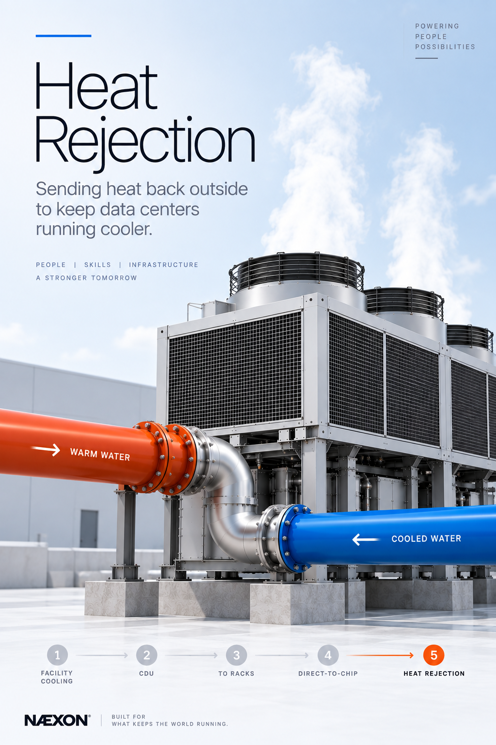
Figure 3. Heat rejection: heated facility water carries absorbed server heat to cooling towers or dry coolers, where the heat is rejected outside before the cooled water returns to the cooling system.
It might seem easier to connect facility chilled water directly to every server, but separating the systems can provide important advantages.
The technology cooling loop may require different temperatures, pressures, flow conditions, water chemistry, filtration, cleanliness standards, or control strategies than the building’s main cooling system.
The CDU creates a controlled boundary.
A heat exchanger can transfer thermal energy across that boundary while keeping the two fluids separated.
For a pipefitter, this creates an important field question whenever approaching a CDU:
Which side am I working on?
Never assume the two connections operate under identical conditions simply because they terminate at the same piece of equipment.
From Large-Bore Pipe to the Processor
One of the most interesting aspects of liquid-cooled data centers is how dramatically the piping scale can change.
A pipefitter might begin in a mechanical plant installing substantial cooling-water mains. Those mains branch throughout the building toward smaller distribution systems.
Eventually the cooling network reaches CDUs.
From there, smaller secondary piping can continue toward rack manifolds. Connections from those manifolds ultimately supply individual computing equipment.
The system essentially progresses from:
Mechanical Plant → Main Piping → Branch Piping → CDU → Distribution Manifold → Rack → Server → Processor
For the mechanical trades, that means the cooling system can extend almost all the way to the computer chip itself.
Cleanliness Becomes Extremely Important
Industrial pipefitters already understand system cleanliness, but liquid-cooled computing makes the consequences especially clear.
Welding debris, rust, scale, dirt, gasket material, excessive sealant, or other contamination can travel through a piping system if proper construction and flushing procedures are not followed.
Large industrial equipment may tolerate certain contaminants better than small cooling passages and specialized components.
That means protecting open pipe, maintaining clean fabrication practices, properly flushing systems, cleaning strainers and filters, and following project-specific water-quality requirements become essential parts of construction.
A useful field rule is:
If you would not want it passing through a small heat exchanger, control valve, pump, or server cooling passage, do not leave it inside the pipe.
Leak Prevention Takes on a Different Meaning
Every piping system should be leak-free.
But consider what may be underneath a liquid-cooling connection inside a data hall: servers containing expensive processors, electrical equipment, power distribution, networking hardware, and critical computing infrastructure.
A small mechanical problem can therefore become a major operational problem.
Proper joint preparation, correct gasket installation, flange alignment, fitting engagement, tubing connections, support, vibration control, pressure testing, and inspection all become extremely important.
This is precision mechanical work performed beside sensitive electronics.
Redundancy Still Rules
Like most critical data-center infrastructure, liquid cooling can incorporate redundancy.
There may be redundant pumps, CDUs, cooling loops, control systems, power supplies, or distribution paths depending on the design.
But installing duplicate equipment does not automatically create redundancy.
The piping and valves must allow equipment to be isolated appropriately.
If one CDU requires maintenance, the system may be designed so another can continue supporting the required cooling load.
That is the same industrial principle seen throughout critical facilities:
Redundancy only works when the system around the redundant equipment allows it to work.
What Pipefitters Should Pay Attention To
When working around CDU and liquid-cooling infrastructure, the fundamentals remain familiar. Identify supply and return. Verify flow direction. Understand which side of the heat exchanger you are connecting. Follow valve orientation requirements. Keep piping clean. Protect equipment nozzles. Provide proper support. Maintain access to valves, filters, instruments, and pumps. Understand vents and drains. Follow testing and flushing procedures carefully.
Most importantly, understand where the fluid is going.
A worker who understands the entire cooling path can recognize problems that someone focused only on the immediate spool may miss.
The Technology Is New. The Fundamentals Are Not.
The CDU may seem like an entirely new type of equipment because it sits inside one of the newest industrial markets.
Look inside it, however, and the basic principles are familiar.
There is fluid.
There is pressure.
There is flow.
There are pumps.
There are valves.
There is a heat exchanger.
There is instrumentation.
And there is heat that needs to be moved from one location to another.
The remarkable part is the destination.
Industrial piping systems that once seemed far removed from the computer industry are now being constructed specifically to remove heat from some of the world’s most powerful processors.
For pipefitters, welders, millwrights, controls technicians, and mechanical contractors entering the data-center market, the CDU provides a perfect example of where the trades are heading.
The computer may create the heat. The mechanical system still has to move it.
Leave a Reply