Morning Edition • Primary trade: Machinists • Skill level: Apprentice • Classification: Fundamentals • Estimated reading time: 9 minutes
What you’ll learn: how surface speed, diameter, and spindle RPM are related; how to calculate an illustrative starting RPM in inch or metric units; and how to recognize a result that used the wrong diameter or units.
A machinist can enter 600 RPM on two jobs and create two very different cutting conditions. Put that speed on a 1-inch diameter, and the cutting edge sees only half the surface travel it would see on a 2-inch diameter. The spindle display has not changed, but the speed at the contact point has.
That distinction is the foundation of speeds and feeds. Spindle speed counts revolutions per minute. Surface speed measures the linear distance that the work or tool surface moves past the cutting edge each minute. Once an apprentice understands why diameter connects them, the formula stops looking like a number to memorize.
Surface speed is distance at the cutting edge
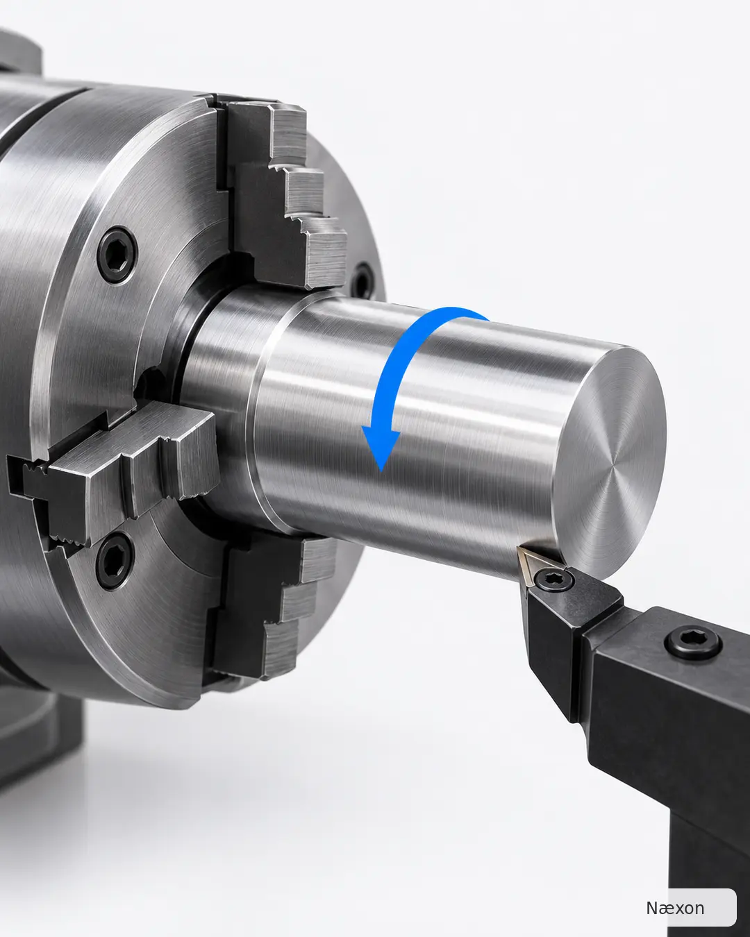
In turning, the workpiece rotates while the cutting tool stays at the contact point. In milling and drilling, the cutter rotates. Either way, the relevant diameter is the rotating diameter at the cutting action. One complete revolution moves one circumference past the edge, and circumference equals π times diameter.
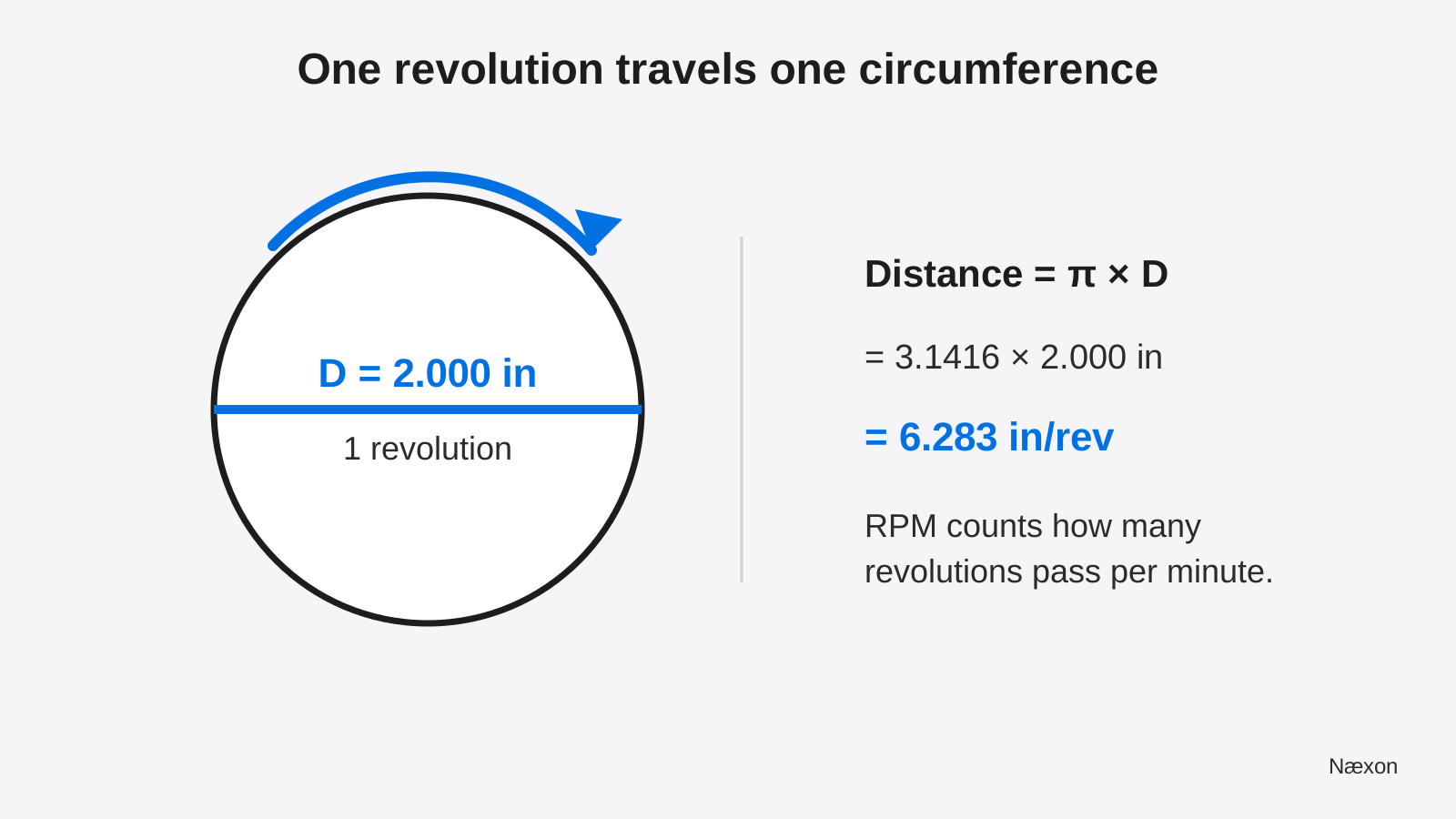
If a 2.000-inch workpiece turns once, 6.283 inches of its surface passes the tool. If it turns 573 times in one minute, multiply 6.283 inches per revolution by 573 revolutions per minute. The result is about 3,600 inches per minute. Dividing by 12 inches per foot gives about 300 surface feet per minute, commonly written SFM.
That unit path explains the inch formula:
SFM = (π × D × RPM) ÷ 12
Here, D is diameter in inches, RPM is revolutions per minute, and 12 converts inches to feet. Rearranging to find spindle speed gives:
RPM = (SFM × 12) ÷ (π × D)
Because 12 ÷ π is approximately 3.8197, many shop references use the shortcut RPM = (SFM × 3.82) ÷ D. The shortcut is a rounded form of the same equation, not a different rule.
For metric work, cutting speed is commonly expressed in meters per minute and diameter in millimeters:
RPM = (m/min × 1000) ÷ (π × Dmm)
The factor 1000 converts meters to millimeters. Keep one unit system through the calculation. Mixing an inch diameter with the metric factor, or a millimeter diameter with the inch formula, produces a result that may look precise but is wrong.
Diameter controls the required RPM
At a constant target surface speed, diameter and RPM move in opposite directions. Double the diameter and the required RPM is cut in half. Halve the diameter and the required RPM doubles. This relationship matters on a lathe as the tool moves from a large outside diameter toward a smaller diameter, and it matters in milling when changing cutter sizes.
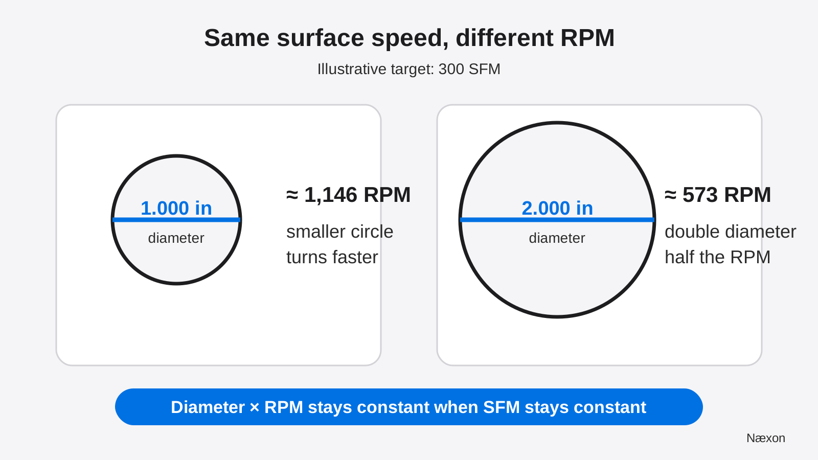
A common incorrect approach is to copy the RPM from a smaller tool or diameter because the material is the same. That fails because material is only one input. Diameter changes the distance traveled in every revolution. Recognize the mistake when two substantially different diameters have the same entered RPM despite a supposedly unchanged surface-speed target. A correct comparison shows diameter multiplied by RPM staying approximately constant.
Where the target surface speed comes from
The formula converts a chosen surface speed into RPM; it does not choose the surface speed. Production cutting data must come from the cutting-tool manufacturer’s current guidance and the approved shop process, then be evaluated for work material, hardness or condition, tool material and grade, coating, insert geometry, coolant strategy, rigidity, depth of cut, machine power, workholding, and machine speed limits.
Do not treat a value from a training example as a universal recommendation. A calculated number may exceed the machine’s rated spindle speed, the chuck or workholding limit, the toolholder limit, or the safe limit for an interrupted or unbalanced setup. The lowest applicable approved limit controls. Programming, setup, and verification remain the responsibility of qualified personnel following the machine, tooling, and shop procedures.
Worked example: calculate an illustrative turning speed
Assume a paper training exercise specifies a target cutting speed of 300 SFM for a 2.000-inch rotating diameter. These values are illustrative only. They are not a recommendation for a particular material, insert, machine, or workholding setup.
Define the variables: V = 300 ft/min, D = 2.000 in, and n = spindle speed in rev/min. Use the full inch formula:
n = (V × 12 in/ft) ÷ (π × D)
n = (300 ft/min × 12 in/ft) ÷ (3.1416 × 2.000 in/rev)
The feet and inches cancel correctly, leaving revolutions per minute:
n = 3,600 in/min ÷ 6.2832 in/rev = 572.96 rev/min
Rounded to the nearest whole revolution for the worksheet, the calculated speed is 573 RPM. On a real machine, do not round upward automatically or force a setting the machine does not provide. Select an allowed setting according to the tooling data, machine controls, approved procedure, and qualified supervision.
Now verify independently by solving back for surface speed:
SFM = (π × 2.000 in × 573 rev/min) ÷ 12 in/ft = 300.02 ft/min
The small 0.02 SFM difference is caused by rounding 572.96 to 573. The reasonableness check also works: at 2 inches diameter, the common 3.82 shortcut gives 300 × 3.82 ÷ 2 = 573 RPM. Both methods agree, and the units cancel as expected.
A practical calculation method
- Identify the rotating diameter. For turning, use the work diameter at the cut. For milling or drilling, use the applicable cutting diameter defined by the tool manufacturer; special geometries may use an effective diameter rather than the nominal body size.
- Obtain the target cutting speed. Use current manufacturer data and the approved shop process for the exact material, tool, and operation. Do not invent a value from memory.
- Choose one unit system. Pair SFM with inches, or meters per minute with millimeters.
- Write the formula with units. Substitute values only after labeling them. This makes a mixed-unit error visible.
- Calculate without early rounding. Carry several digits through the division, then round only the final worksheet result as appropriate.
- Check the limits. Compare the result with all applicable machine, spindle, chuck, toolholder, cutting-tool, workholding, and process limits.
- Reverse-check the answer. Put the selected RPM back into the surface-speed formula and confirm that the result is close to the intended value.
For arithmetic and unit conversions, Næxon Numerus can help reduce transcription errors, but the machinist must still select the correct formula, diameter, cutting data, and controlling limits.
Troubleshooting a suspicious result
The RPM is about 25.4 times too high or too low. Check for an inch-versus-millimeter mix. The conversion between one inch and 25.4 millimeters often leaves this fingerprint.
The RPM did not change when diameter changed. The old diameter may still be in the calculation, or a copied machine setting may have replaced the calculation. Re-enter the actual rotating diameter.
The calculated RPM exceeds an equipment limit. Stop. Do not enter the value merely because the arithmetic is correct. Verify every applicable rating and obtain qualified direction for an approved adjustment.
Tool life or finish is poor even though the formula is correct. RPM is only one variable. Confirm actual diameter, tool identification, insert or cutter data, feed, depth of cut, runout, rigidity, workholding, coolant, material condition, and machine condition. Escalate unexpected vibration, movement, damage, or limit conflicts before cutting continues.
Common mistakes
Frequent errors include using radius instead of diameter, forgetting the 12-inch or 1000-millimeter conversion, choosing the nominal stock size after the diameter has changed, substituting feed rate for surface speed, rounding the 3.82 shortcut too early, and treating a calculated RPM as authorization to run the machine.
Another mistake is using the same diameter rule for every special cutter. Ball-nose tools, round-insert cutters, and tools cutting away from their nominal outside diameter may require an effective cutting diameter supplied or defined by the tool manufacturer. If the applicable diameter is uncertain, stop at the calculation stage and consult the tooling documentation or qualified shop support.
Field Rules
- Surface speed is linear travel at the cutting edge; RPM is rotation per minute.
- One revolution travels π times the rotating diameter.
- At constant surface speed, larger diameter means lower RPM.
- Use SFM with inches or meters per minute with millimeters—never a mixed pair.
- Obtain cutting data and limits from approved sources for the actual setup.
- Reverse-check the selected RPM before it becomes a machine setting.
- A correct calculation never overrides a machine, tool, workholding, or process limit.
Knowledge Check
- A worksheet specifies 240 SFM and a 1.500-inch diameter. Using RPM = (SFM × 12) ÷ (π × D), what is the calculated RPM to the nearest whole number?
- A machinist changes from a 1-inch cutter to a 2-inch cutter while keeping the same target SFM. Should the calculated RPM double, halve, or stay the same?
- A calculation pairs a 50 m/min target with a diameter entered as 0.500 because the tool is one-half inch. What error must be corrected before solving?
- The formula returns 8,200 RPM, but the setup documentation lists a lower controlling limit. Which value governs?
- A result was calculated with diameter rather than radius, the units cancel correctly, and the reverse calculation returns the target SFM. What has this combination of checks established—and what has it not established?
Answers
- About 611 RPM: (240 ft/min × 12 in/ft) ÷ (π × 1.500 in/rev) = 611.15 rev/min, rounded to 611. Reverse-checking gives about 239.94 SFM.
- The RPM should halve. With unchanged surface speed, doubling diameter requires half as many revolutions per minute.
- The calculation mixes metric cutting speed with an inch diameter. Convert 0.500 inch to 12.7 millimeters and use the metric formula, or convert the target to SFM and use the inch formula.
- The lower approved limit governs. Arithmetic does not authorize exceeding any machine, tool, chuck, toolholder, workholding, or process rating.
- The checks establish that the arithmetic and unit handling are internally consistent. They do not prove that the target surface speed is correct for the actual material and tool, or that the setup is safe and within every applicable limit.
Practical Exercise
On paper only, create a three-row table for diameters of 1.000, 1.500, and 2.000 inches at an illustrative 300 SFM. Calculate RPM with the full formula, round each final answer to the nearest whole RPM, and reverse-check each result. Expected answers are approximately 1,146 RPM, 764 RPM, and 573 RPM. Your reverse checks should return about 300 SFM, with only small differences from rounding. Then write one sentence explaining why the largest diameter uses the lowest RPM. Do not use these training values to operate equipment.
Related learning
Build the measurement skill behind diameter selection with Precision Measurement: Using Calipers, Micrometers, and Dial Indicators. For a broader look at rotating-equipment calculations and unit discipline, continue to Field Formulas for Millwrights. A later application of measured movement and machine geometry appears in the industrial machinery alignment guide.