Evening Edition · Instrumentation and controls technicians · Intermediate · Troubleshooting · 9-minute read
What you will learn: Recognize the normal service state of a three-valve manifold, explain why an open equalizer can drive differential pressure toward zero, and choose safe checks before blaming the transmitter.
The transmitter display is alive, the loop current reaches the control system, and the process is running—but the indicated flow stays near zero. Replacing the transmitter may seem like the fastest answer. In many cases, however, the sensing element is reporting exactly what reaches it. The real problem is the valve state or pressure path between the process and the transmitter.
This lesson focuses on a common three-valve manifold installed with a differential-pressure, or DP, transmitter. It is an educational troubleshooting framework, not permission to operate a live manifold. Process pressure, temperature, toxicity, vent routing, and the transmitter model all matter. Follow the approved procedure, drawings, permits, manufacturer instructions, and qualified supervision before touching any valve.
What the manifold does
A DP transmitter compares pressure at its high-pressure port with pressure at its low-pressure port. The measured differential is written as ΔP = PH − PL. In flow service, those two pressures may come from opposite sides of a primary element such as an orifice plate. In level service, they may represent liquid head on one side and vessel or reference pressure on the other.
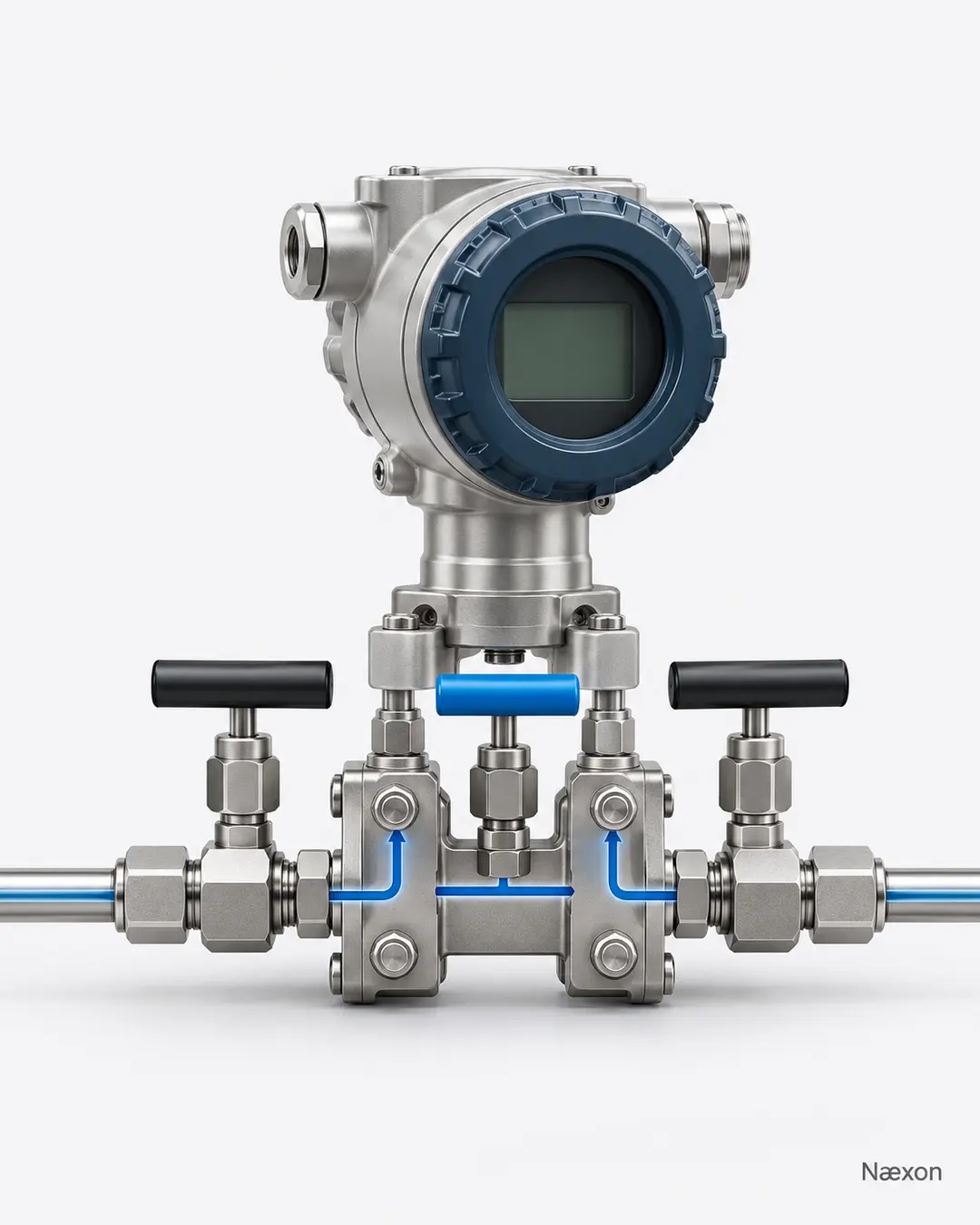
A three-valve manifold has a high-side isolation valve, a low-side isolation valve, and a center equalizing valve. The isolation valves connect or separate each transmitter port from its corresponding process impulse line. The equalizer connects the two transmitter ports to each other. This arrangement supports controlled isolation, equalization, and zero checks when the equipment design and procedure permit them.
For normal DP service, the common state is both isolation valves open and the equalizer closed. The high side then receives PH, the low side receives PL, and the sensing element can measure their difference. Figure 1 shows that relationship without depending on a specific handle shape or turning direction.
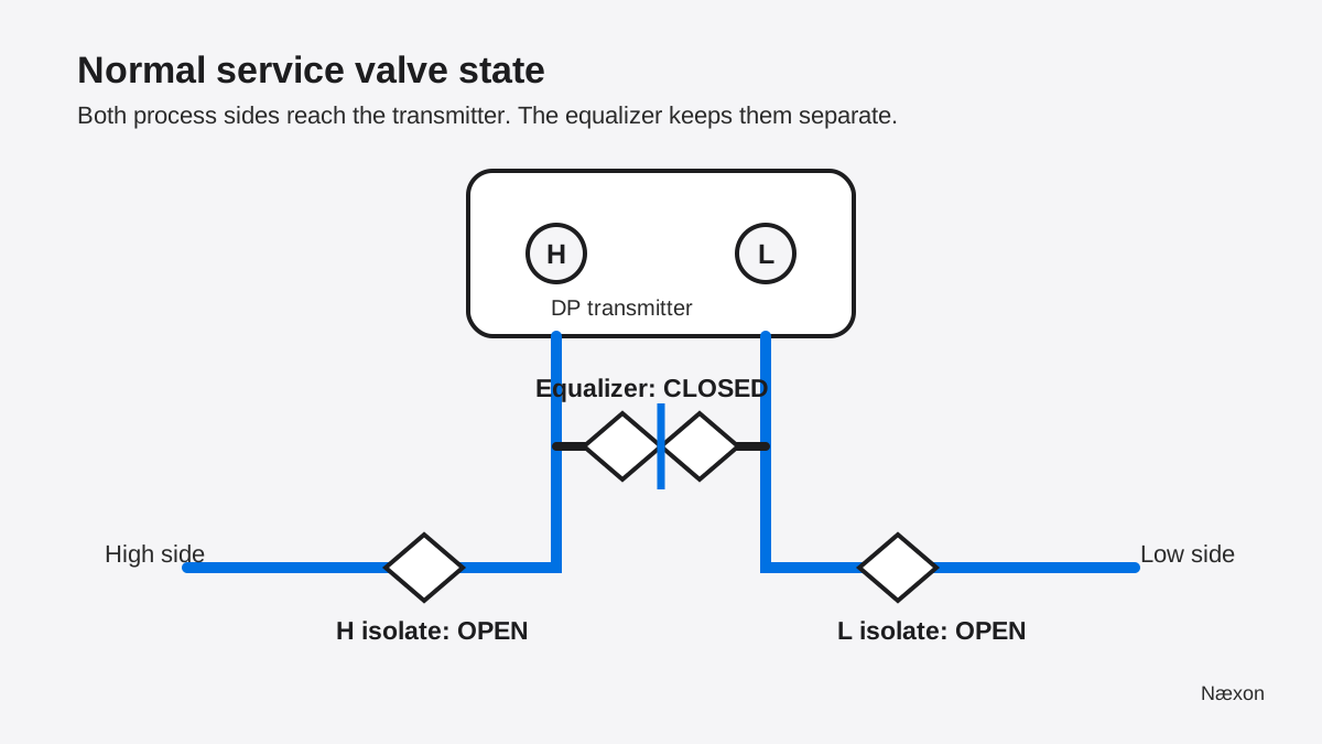
Valve construction and operating sequence vary. A drawing that says “open” does not tell you how many turns, which direction, whether a vent must be routed, or whether the process can tolerate the change. Those details belong to the approved procedure and manufacturer documentation.
Why an open equalizer can make the reading collapse
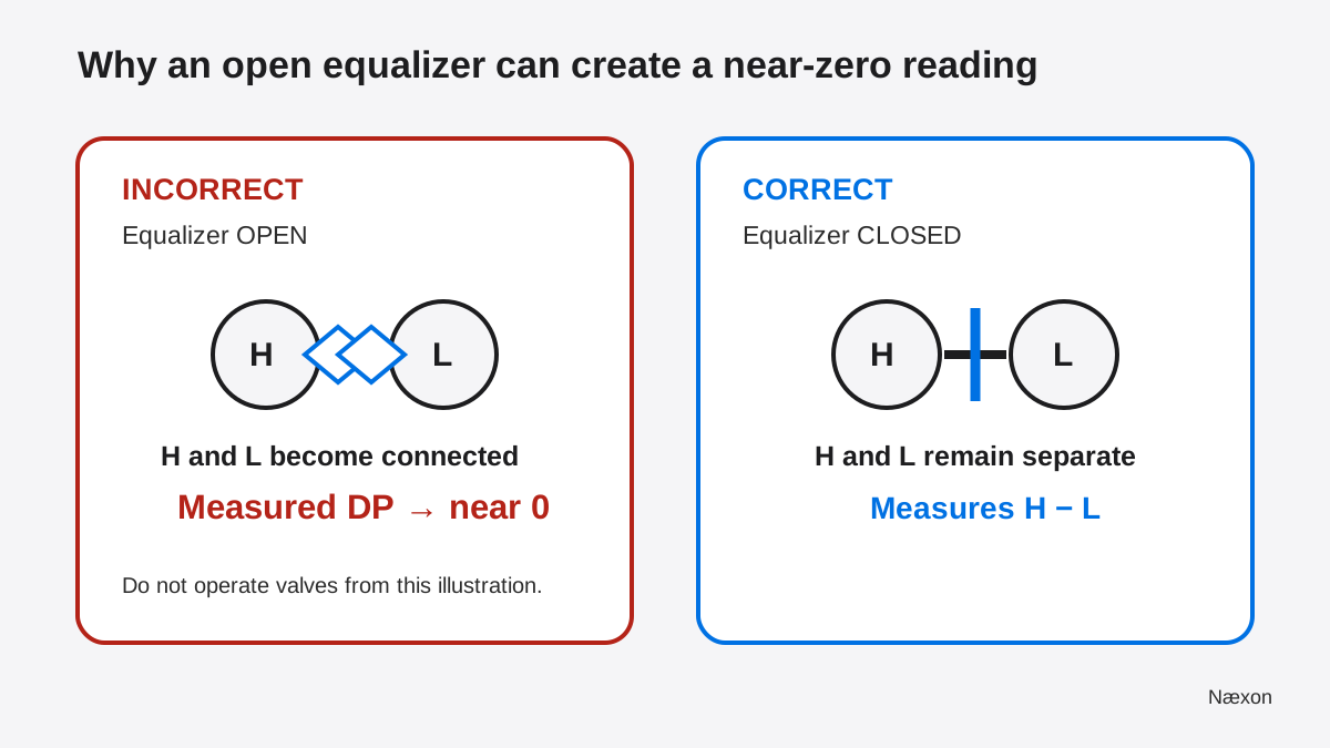
Suppose the process creates 80 inH₂O at the high port and 20 inH₂O at the low port. With separate paths, the transmitter sees 80 − 20 = 60 inH₂O. If the equalizer is opened while both sides communicate through the manifold, the ports are connected. Pressure tends to balance across the sensor, so the measured differential moves toward zero even though the process itself may still have a real pressure difference.
That is why a powered transmitter with a believable zero is not automatically a healthy process measurement. The device may be healthy, the electrical loop may be healthy, and the manifold may be placing nearly equal pressure on both sides. Figure 2 compares the fault condition with the normal service state. The incorrect state is shown only for recognition; it is not an instruction to reproduce it on operating equipment.
Field application: separate the symptom from the cause
Start by confirming the process should actually create a differential. A stopped pump, closed upstream valve, empty vessel, bypassed primary element, or true no-flow condition can produce a correct zero. Compare the indication with operating status, a second independent measurement, and the approved process drawing. Do not assume the operator’s expectation is proof of flow.
Next, compare the manifold’s documented valve state with the physical position indicators available on that exact assembly. Some needle valves use rising stems; others do not. Handles can be removed or installed in misleading orientations. Treat appearance as evidence to verify, not as a universal position standard.
If the expected DP exists but the transmitter sees little or none, possible causes include an equalizer that is open or leaking through, an isolation valve that is closed, both ports connected to the same pressure source, or an impulse-line problem. A blocked high-side line commonly biases the reading low. A blocked low-side line can bias it high or cause a sluggish response. Trapped gas in liquid service, trapped liquid in gas service, unequal condensate legs in steam service, leaks, or poor heat tracing can also distort the pressure delivered to the sensor.
Only after the pressure path and valve state are understood should the electrical signal become the main suspect. The existing lesson on a correct field signal that appears wrong in the control room covers the downstream side of that diagnosis. For a prerequisite on the signal itself, review how 4–20 mA loops work.
Worked example: a false low flow indication
Consider an illustrative orifice-flow application. The engineering range defines 100 inH₂O as the DP at 100% design flow. The transmitter now reports 25 inH₂O. Assume the square-root relationship is applicable, density and primary-element conditions match the design basis, the transmitter range is correct, and square-root extraction is performed only once. These are training assumptions, not project acceptance criteria.
Let Q% be indicated flow as a percentage of design flow, ΔP be the measured differential, and ΔPmax be the differential at design flow. The relationship is:
Q% = √(ΔP ÷ ΔPmax) × 100%
Substitute the values while carrying units:
Q% = √(25 inH₂O ÷ 100 inH₂O) × 100% = √0.25 × 100% = 50%
The pressure units cancel inside the ratio. No rounding is needed because √0.25 is exactly 0.5. A reverse check squares the flow fraction: 0.50² × 100 inH₂O = 25 inH₂O. The arithmetic is internally consistent.
The reasonableness check is equally important: in a square-root relationship, one-quarter of full-scale DP corresponds to one-half of full-scale flow. But that does not prove the process is at 50% flow. If an equalizer is leaking or partly open, the 25 inH₂O is not a faithful process differential. Verify the pressure path before using the calculation for an operating decision.
A safe troubleshooting sequence
- Confirm the expected process condition. Use approved operating information, drawings, and an independent indication where available. Establish whether a real DP should exist.
- Identify the exact manifold and ports. Trace the H and L connections from the process to the transmitter. Do not rely on handle color alone.
- Compare documented and observed valve states. The common normal state is H isolate open, L isolate open, equalizer closed, but the approved procedure controls.
- Look for pressure-path clues. Check for documented maintenance isolation, plugged impulse lines, leaks, trapped phase, frozen or overheated tubing, unequal wet legs, or recent work.
- Compare local and control-system values. If local DP is reasonable but the control-room value is wrong, move downstream to range, scaling, wiring, and input-channel checks.
- Stop at the boundary of authorization. If resolving the symptom requires operating valves, venting, draining, breaking containment, bypassing a trip, or exposing energized circuits, stop and use the approved work process with qualified supervision.
Troubleshooting by symptom
Near zero while the process should be flowing: verify actual process operation, then investigate an open or passing equalizer, closed isolation valves, common pressure connected to both ports, or two blocked impulse paths. A stable zero can be a manifold condition rather than an electronics failure.
Reading is much lower than expected: compare the high-side path with the low-side path. A restricted high-side line, leak, partially communicating equalizer, trapped gas in a liquid line, or range/configuration issue can reduce indicated DP.
Reading is high or off-scale: consider a restricted or closed low-side path, reversed H and L connections, a reference-leg problem, or a transmitter range mismatch. Do not loosen plugs or vents to “see what comes out.”
Reading responds slowly: inspect the history of impulse-line plugging, viscous process fluid, long tubing runs, dampening settings, partially closed valves, condensate, and temperature effects. Escalate when the process medium or pressure makes field checks hazardous.
Common mistakes
The first mistake is replacing the transmitter before checking what pressure reaches it. A new transmitter connected to the same incorrect valve state will usually produce the same bad measurement.
The second is treating the center valve as a bypass that can remain open during measurement. An equalizer is useful during approved isolation or zero procedures, but leaving it open defeats the transmitter’s ability to sense a difference.
The third is applying a memorized valve sequence to every manifold. Three-valve, five-valve, remote-mount, direct-mount, and wet-leg installations differ. Process hazards and manufacturer instructions change the safe sequence.
The fourth is trusting handle orientation without verifying the valve design. Position indicators, stem movement, tags, drawings, and the exact manifold manual are stronger evidence than a generic “handle parallel means open” rule.
The fifth is performing square-root extraction twice—once in the transmitter and again in the control system. That creates a nonlinear error unrelated to the manifold, so confirm where extraction is configured.
Field Rules
- Verify that the process should create DP before calling the reading wrong.
- Normal service commonly means both isolates open and the equalizer closed.
- An open equalizer can make a healthy transmitter report near zero.
- Trace H and L; never diagnose from handle color alone.
- Use the approved sequence for the exact manifold and service.
- Do not vent, drain, or break containment as an informal test.
Knowledge Check
- A flow transmitter reads nearly zero, but a pump is running and another approved indicator shows flow. What manifold condition should be checked early?
- In Figure 1, why must the equalizer be closed for normal DP measurement?
- An orifice application has 100 inH₂O at design flow and a valid measured DP of 36 inH₂O. Under the stated square-root assumptions, what percent of design flow is indicated?
- The local transmitter display agrees with the expected DP, but the control-room value is wrong. Should the next check focus first on the manifold or on the signal path?
- A technician cannot confirm the valve state without venting a toxic process. What is the correct next action?
Answers
1. Check whether the equalizer is open or passing and whether the two isolation paths match the approved normal state. First confirm the process expectation; a true zero remains possible.
2. Closing the equalizer keeps PH and PL separate. If it is open, the ports communicate and the measured difference moves toward zero.
3. √(36 ÷ 100) × 100% = √0.36 × 100% = 60%. Reverse-check: 0.60² × 100 inH₂O = 36 inH₂O.
4. Focus next on the signal path—loop current, scaling, wiring, channel configuration, and where square-root extraction occurs—because the local pressure measurement already appears reasonable.
5. Stop and escalate through the approved work process. Do not vent toxic, hot, pressurized, or otherwise hazardous material merely to diagnose an indication.
Practical Exercise
On paper, draw a DP transmitter with H and L ports and a three-valve manifold. Mark the normal service state, then redraw the same manifold with the equalizer open. Write one sentence explaining the expected indication in each case. Next, calculate indicated flow for 16 inH₂O on a 64 inH₂O design-DP basis using the square-root relationship.
Your checking result should show both isolation valves open and the equalizer closed for the normal-service drawing. The equalized drawing should show the H and L ports connected and DP moving toward zero. The calculation should produce √(16 ÷ 64) × 100% = 50%, with the reverse check 0.50² × 64 inH₂O = 16 inH₂O. Keep this exercise paper-based or use a supervised training manifold that is isolated from process service.
Related learning
Build the prerequisite first with pressure-transmitter calibration fundamentals. Then use this lesson to separate a sensing-path problem from an electrical problem. A useful next step is field troubleshooting of a bad 4–20 mA signal, which continues the diagnosis from the transmitter terminals toward the control system.