Evening Edition · Pipefitters and steamfitters · Intermediate · Print Reading · 10-minute read
What you will learn: Read a pipe centerline elevation, convert outside diameter to radius, apply the approved pipe-shoe dimension, and calculate the supporting top-of-steel elevation with an independent check.
The pipe rack steel is being laid out, but the piping isometric gives only a centerline elevation. The support detail shows a shoe under the pipe. Where should the top of the beam actually land?
This is a common interface between piping and structural work. The arithmetic is short, but the reference points must be exact. Subtracting the wrong pipe dimension or misreading what the shoe height measures can place the steel several inches out of position. This lesson shows a disciplined method for turning pipe centerline elevation into a top-of-steel elevation. It does not design the shoe, establish allowable loads, or replace approved piping, structural, and support drawings.
Three elevations, two vertical dimensions
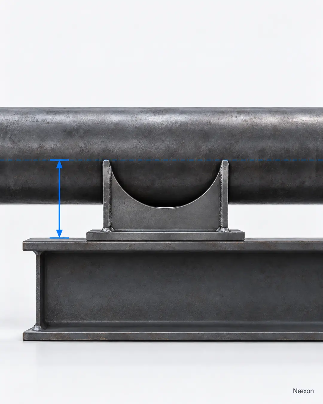
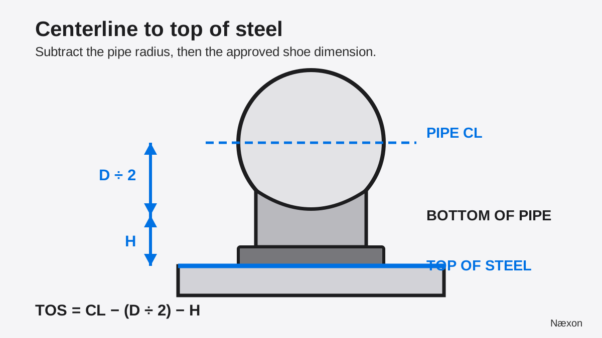
Start with three horizontal reference planes. The pipe centerline, or CL, passes through the center of the pipe. The bottom of pipe, or BOP, is one pipe radius below centerline. The supporting top of steel, or TOS, is the bearing elevation beneath the shoe or specified contact layer.
The first vertical dimension is the pipe radius. If D is the pipe outside diameter, the radius is D ÷ 2. Nominal pipe size is a name, not the outside diameter used in this calculation. Verify the actual outside diameter from the piping specification, approved drawing, or a controlled dimensional reference. Næxon In-dex can assist with component and dimensional reference work, but project documents still control.
The second dimension is the project-defined shoe dimension, called H in this lesson. Here, H means the vertical distance from the bottom of pipe to the shoe bearing surface at top of steel. A support drawing may use a different label or measure from a different reference. Do not assume every note called “shoe height” means the same thing. Trace the support tag to its approved detail and read the dimension arrows.
With those definitions, the relationship is:
BOP = CL − (D ÷ 2)
TOS = BOP − H
Combined into one line:
TOS = CL − (D ÷ 2) − H
This equation is valid only when H is measured vertically from BOP to the bearing surface whose elevation you need. If the detail includes a slide plate, wear plate, insulation assembly, standoff, or another layer, follow the reference shown on the approved detail. Pipe shoes are not interchangeable blocks. Their configuration, attachment, movement function, material, insulation interface, and load capacity are engineering decisions.
Worked example: centerline to top of steel
Assume a training isometric gives pipe centerline elevation EL 112 ft 6 in. The pipe is NPS 8 with a verified outside diameter D = 8.625 in. = 8 5/8 in. The approved support detail for this example defines H = 6 in. from bottom of pipe to the shoe bearing surface. These values are illustrative; they are not universal shoe dimensions or project acceptance criteria.
First find the radius:
D ÷ 2 = 8 5/8 in. ÷ 2 = 4 5/16 in.
Then subtract the radius and H from centerline elevation:
TOS = 112 ft 6 in. − 4 5/16 in. − 6 in.
Subtract the shoe dimension first: 112 ft 6 in. − 6 in. = 112 ft 0 in. Then subtract 4 5/16 in. Borrow one foot, or 12 inches:
112 ft 0 in. − 4 5/16 in. = 111 ft 7 11/16 in.
The required supporting elevation is therefore EL 111 ft 7 11/16 in.
A decimal-unit check reaches the same result. Centerline is 112 × 12 + 6 = 1,350 inches above the chosen datum. Subtract 4.3125 inches and 6 inches:
1,350 in. − 4.3125 in. − 6 in. = 1,339.6875 in.
Divide by 12: 111 feet remains with 7.6875 inches, and 0.6875 inch equals 11/16 inch. The answer is again 111 ft 7 11/16 in. No rounding was required. If a project specifies an elevation precision or rounding convention, follow that requirement rather than inventing one.
The reverse check is equally important:
111 ft 7 11/16 in. + 6 in. + 4 5/16 in. = 112 ft 6 in.
A reasonableness check also works. TOS must be below BOP, and the total drop from centerline must equal one radius plus the shoe dimension: 4 5/16 in. + 6 in. = 10 5/16 in. The calculated steel is 10 5/16 inches below centerline, so the direction and magnitude make sense.
The full-diameter mistake
A frequent error is to subtract the full outside diameter from centerline. That treats centerline as though it were at the top of pipe. Centerline is halfway through the circular cross-section, so the distance from centerline to BOP is one radius, not one diameter.
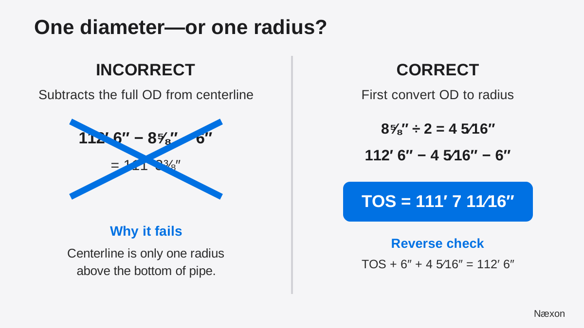
The wrong calculation produces EL 111 ft 3 3/8 in., which is 4 5/16 inches lower than the correct result. The error can be recognized by comparing the calculation chain to a pipe section: if the first drop from CL to BOP is labeled with the full OD, the reference is wrong. The correction is to divide the verified OD by two before applying the support-detail dimension.
A field method that protects the references
- Identify the controlling datum. Confirm that the piping elevation and structural elevation use the same project datum and units. Review industrial elevations, benchmarks, and datums if the reference system is unfamiliar.
- Read the pipe centerline. Locate the elevation callout on the correct line and segment. On congested isometrics, trace coordinates and line identification carefully; reading coordinates on piping isometrics is a useful prerequisite.
- Verify outside diameter. Use the project piping specification, approved line information, or a controlled dimensional source. Do not substitute nominal pipe size for OD.
- Open the support detail. Match the support tag exactly. Determine what H measures, where the bearing plane is, and whether plates or other components are included in that dimension.
- Calculate in one unit system. Keep feet-and-inches fractions aligned or convert the entire elevation to decimal inches. Write the reference beside every number.
- Reverse-check the result. Add H and the pipe radius back to TOS. The sum must reproduce the stated centerline elevation.
- Coordinate with structural information. Compare the calculated bearing elevation with the approved steel elevation and connection detail. A mismatch is a coordination issue, not permission to modify the support.
Troubleshooting an elevation that does not agree
The calculated TOS and structural drawing differ: verify the datum, units, drawing revision, pipe line, support tag, outside diameter, and H reference. Check whether the structural elevation is beam top, plate top, grout top, or another surface. If the controlling documents still disagree, stop and raise the discrepancy through the project process.
The pipe fits the centerline but the shoe does not bear: confirm that the installed shoe matches the approved type and orientation, that the intended bearing or slide plate is present, and that pipe slope or thermal position has not been ignored. Do not fill a gap with loose material or force the pipe down.
The support tag is missing or unreadable: do not select a shoe by appearance. Similar-looking supports can serve different movement, insulation, and loading requirements. Obtain the approved identification and detail before fabrication or installation proceeds.
The field elevation changes after the system is hot or loaded: thermal movement, deflection, or operating loads may change position. Never jack, restrain, cut, weld, or remove a support on energized, hot, pressurized, or loaded equipment without the approved procedure, isolation, engineering direction, and qualified supervision.
Common mistakes
Using nominal pipe size as OD changes the radius. Subtracting the full OD doubles the centerline-to-BOP drop. Treating every “shoe height” as BOP-to-steel ignores the actual dimension arrows. Mixing decimal feet with feet-and-inches fractions creates silent conversion errors. Reading beam centerline or bottom of steel as TOS shifts the bearing plane. Finally, modifying a shoe to make mismatched elevations fit can damage the intended load path or movement function.
Field Rules
- Centerline to bottom of pipe equals one-half of the verified outside diameter.
- Define the shoe dimension from the approved detail before using it.
- Name the surface: pipe CL, BOP, bearing surface, plate top, or steel top.
- Keep one datum and one unit system through the calculation.
- Reverse-check TOS + H + radius against the stated pipe centerline.
- Escalate drawing or field conflicts; do not redesign the support in the field.
Knowledge Check
- A calculation subtracts 10.75 inches from centerline for a pipe with a 10.75-inch OD. What reference error should you spot?
- Pipe CL is EL 104 ft 2 in., verified OD is 6.625 inches, and the approved BOP-to-bearing dimension is 5 inches. What is TOS?
- The support schedule says H = 8 inches, but its dimension arrows run from pipe centerline to the shoe base. Can H be inserted into TOS = CL − D/2 − H?
- Your calculation agrees internally, but structural TOS is 1 inch different. What should happen next?
Answers
1. The calculation uses the full OD from centerline to BOP. It should use the radius: 10.75 in. ÷ 2 = 5.375 in., subject to verification of the actual pipe OD.
2. Radius = 6.625 in. ÷ 2 = 3.3125 in. TOS = 104 ft 2 in. − 3.3125 in. − 5 in. = 103 ft 5.6875 in., or EL 103 ft 5 11/16 in. Reverse check: 103 ft 5 11/16 in. + 5 in. + 3 5/16 in. = 104 ft 2 in.
3. No. This lesson defines H from BOP to bearing surface, but that detail measures from CL to base. Use the detail's actual reference directly or rename the variable and reform the equation; do not subtract the radius twice.
4. Recheck datum, revision, surface definition, OD, and support detail. If the difference remains, document and escalate the coordination conflict. Do not move steel or alter the shoe without approved direction.
Practical Exercise
On paper, draw a circle for a pipe section and mark CL, BOP, and a shoe bearing surface. Use illustrative values CL = EL 98 ft 9 in., OD = 12.75 in., and approved BOP-to-bearing H = 7.5 in. Calculate TOS, then reverse-check it. Expected result: radius = 6.375 in.; total drop = 13.875 in.; TOS = EL 97 ft 7 1/8 in. Adding 7 1/2 in. and 6 3/8 in. returns EL 98 ft 9 in. Keep this as a paper exercise; real work requires the approved project dimensions and support detail.
Related learning
For a broader drawing foundation, study how to read piping isometric drawings. The next useful application is calculating pipe dummy-leg dimensions from BOP, CL, and TOP, where the same reference discipline is applied to a different support geometry.