Evening Edition · Millwrights · Apprentice to intermediate · Field Skill · 9-minute read
What you will learn: Recognize a soft-foot pattern, use one-foot-at-a-time movement readings to locate the suspect mounting point, distinguish a flat gap from angled contact, and know when shimming is not the answer.
The laser alignment keeps changing after the motor bolts are tightened. One reading looks good, the next is out, and another shim makes the result move somewhere else. That pattern can make the alignment tool look unreliable when the real problem is below the machine frame.
Soft foot describes a condition in which the machine is not supported evenly at its mounting feet. Tightening a hold-down bolt then pulls a foot toward the base and distorts the frame. That movement can shift the shaft, change alignment readings, load bearings or seals, and make a correction impossible to repeat. The useful field habit is simple: stabilize the mounting condition before treating shaft alignment as the main problem.
This lesson is an educational diagnostic framework. The equipment manufacturer's instructions, site energy-control procedure, approved alignment method, specified tolerances, base design, and qualified supervision control the actual work. Isolate the machine, restrain stored or connected energy, verify de-energization, and follow the approved procedure before removing guards, loosening mounting hardware, or reaching near a coupling.
Soft foot is movement, not just an empty gap
A visible clearance beneath one foot is a strong clue, but soft foot is broader than a simple short-leg condition. A foot may sit uniformly above the base, touch only along one edge, compress debris or a damaged shim stack, or move because pipe strain, conduit, a stiff coupling, or another outside force is twisting the machine.
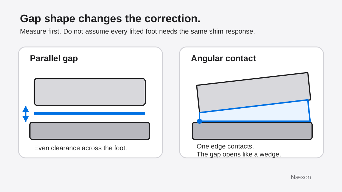
That distinction matters because the measured lift does not automatically equal a shim to install. A flat, repeatable gap may support a flat correction under the approved procedure. A wedge-shaped gap points to angular contact. A reading that changes from cycle to cycle may indicate debris, burrs, damaged shims, loose grout, a flexible base, or an external force. Adding a flat shim without understanding the contact can trade one distortion for another.
What the loosen-one-foot check tells you
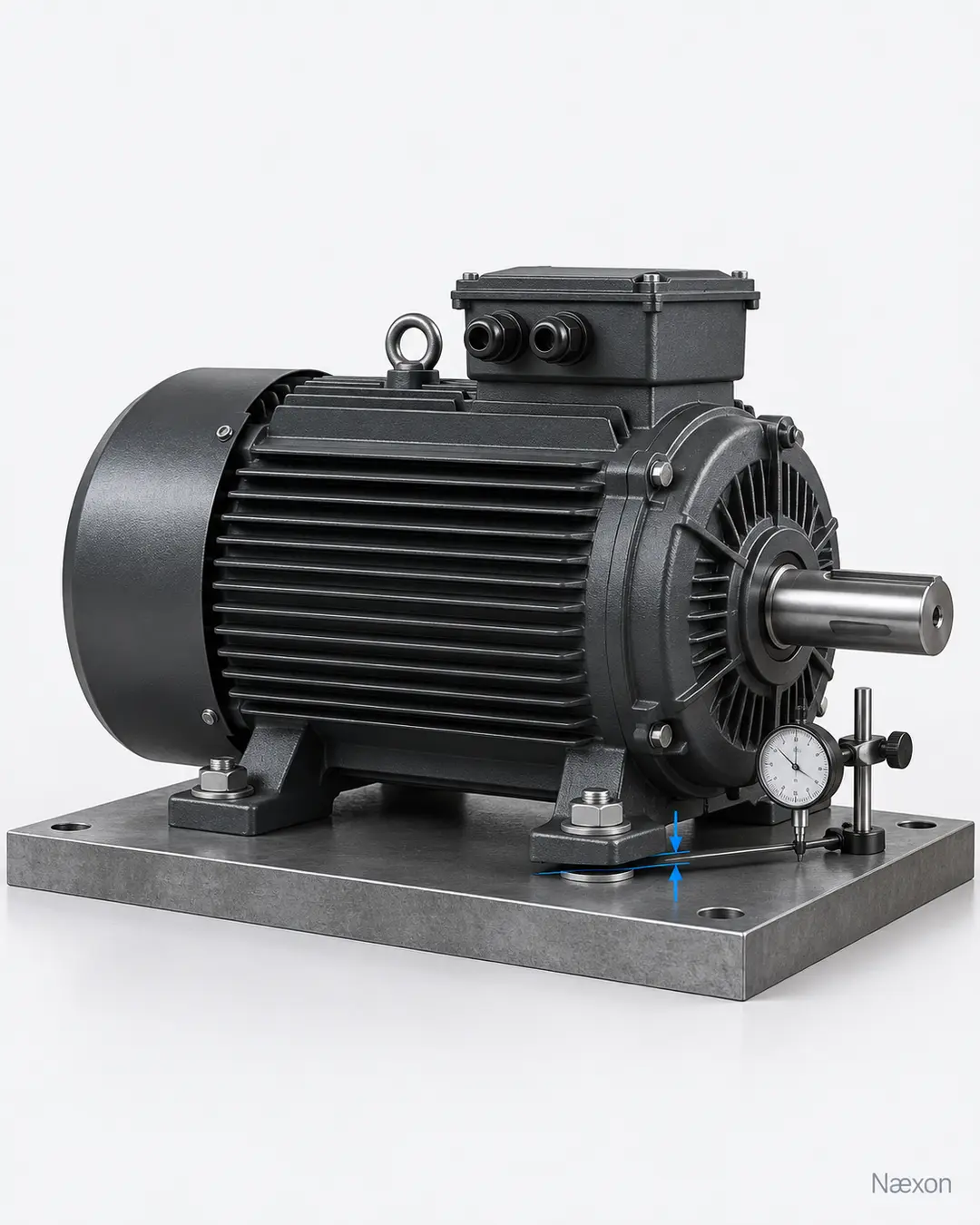
Many soft-foot workflows monitor machine movement while one hold-down is released at a time. A laser alignment system can track shaft movement; an approved dial-indicator setup may track frame or foot movement. The exact setup and release sequence are tool- and machine-specific. Keep the other feet in the procedure's required condition, change only the intended fastener, and return it to the specified state before moving to the next foot.
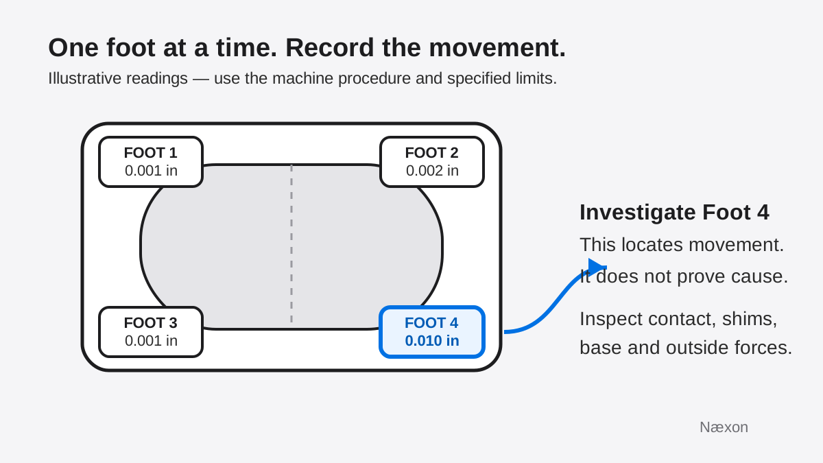
The readings form a pattern. A foot that produces much more movement than the others deserves investigation. The pattern identifies where the machine reacts; it does not, by itself, prove whether the cause is a parallel gap, angular contact, a compressible stack, base distortion, or an outside load.
Worked example: interpret the pattern without inventing a tolerance
Assume a training motor has four feet. Under the approved test method, the recorded movement when each foot is individually released is F1 = 0.001 in, F2 = 0.002 in, F3 = 0.001 in, and F4 = 0.010 in. These are illustrative values, not acceptance criteria.
First compare each reading with the group. The three smaller readings total 0.004 in, so their average is 0.004 in ÷ 3 = 0.00133 in. Rounded to the measurement resolution used in the example, that is about 0.001 in. Foot 4 moves 0.010 in, roughly 0.009 in more than that baseline pattern.
Independently check the arithmetic: 3 × 0.00133 in ≈ 0.00399 in, which returns the original 0.004 in total after rounding. A reasonableness check also works: 0.010 in is several times larger than every other reading, so Foot 4 is the logical place to inspect first.
The conclusion is not “install a 0.010-inch shim.” The defensible conclusion is “Foot 4 shows the dominant movement and requires a contact, shim, base, and external-force inspection.” The equipment or alignment procedure supplies the actual limit and correction method.
Read the shape before choosing the correction
With the machine safely isolated and the foot in the condition required by the procedure, inspect the accessible contact area using the specified method. A feeler gauge can help map where clearance exists, while a micrometer can verify removed shim thickness. Clean, intact surfaces matter: paint ridges, dirt, burrs, corrosion, folded shims, and partial support can all change the reading.
A parallel soft foot shows a generally even clearance between foot and base. An angular soft foot contacts on one edge while the opposite side opens like a wedge. A squishy foot compresses rather than seating solidly, commonly because the stack or contact surface is contaminated, damaged, or unstable. An external-force condition means the frame is being pulled or twisted by something connected to it.
A practical diagnostic sequence
- Establish the safe condition. Follow the site-specific energy-control procedure, isolate every applicable source, control stored energy, verify isolation, and confirm the authorized work scope.
- Review the installation. Check the machine drawing, base and grout condition, hold-down hardware, coupling state, connected piping or conduit, and the manufacturer's alignment instructions.
- Record the starting condition. Note the current shim packs, bolt condition, shaft-alignment result, and any movement seen during final tightening.
- Run the specified soft-foot check. Monitor one foot at a time with the approved tool and sequence. Record actual movement; do not rely on memory.
- Repeat the suspect reading. A repeatable result is stronger evidence than one isolated number. If the reading changes, investigate setup stability, dirt, burrs, stack compression, loose support, or external loading.
- Map the contact. Determine whether the gap is even, angled, compressible, or created by an outside force. Inspect the full accessible footprint and measure removed shims rather than trusting stamped thickness alone.
- Correct the cause under the approved procedure. Clean and restore proper contact, use suitable intact shims where specified, or escalate base, grout, foot, piping, conduit, or frame defects.
- Tighten and verify. Use the specified fastener sequence and torque requirements, repeat the soft-foot check, then perform the shaft alignment. Recheck after final tightening because the secured condition is the result that matters.
Incorrect approach versus correct approach
The common incorrect approach is to see 0.010 in of movement and immediately slide in a 0.010-inch shim. That may appear logical, but it assumes the foot is parallel, the measuring point represents the entire footprint, no debris compresses, the base is rigid, and no external force twists the frame. If any assumption is wrong, the shim can leave edge contact or move the distortion elsewhere.
The correct approach uses the movement reading to choose the next inspection. Map the gap, clean and verify the surfaces, measure the shim pack, check connected systems and base stability, then apply the correction the controlling procedure calls for. A correct result is repeatable: the machine returns to the same position when the feet are secured, and the soft-foot and alignment checks both remain within their specified project or manufacturer limits.
Troubleshooting unstable results
The suspect foot changes every cycle: confirm the instrument setup, brackets, bolt sequence, base stability, and cleanliness. A shifting suspect often points to a system that is settling or rocking rather than one simple short foot.
The reading increases after adding shims: stop adding material. Check whether the gap is angular, whether the shim is too small for the footprint, whether the stack is creased or contaminated, and whether the correction changed another foot's contact.
The machine aligns until final tightening: record movement during the tightening sequence. Recheck soft foot, bolt or washer seating, base condition, and external forces. Do not repeatedly chase the shaft with alignment moves while the frame position is unstable.
Soft foot returns after piping is connected: treat the timing as evidence of an external load. Coordinate with the piping and engineering teams under the project procedure. Moving the motor to hide pipe strain may improve one coupling reading while leaving the casing loaded.
A foot, base, grout, or frame is cracked or visibly distorted: stop and escalate. Shims are not a repair for damaged structure, failed grout, an unsuitable foundation, or an unauthorized machine-frame modification.
Common mistakes
Frequent errors include skipping soft-foot checks until after alignment, loosening more than one foot when the method requires one, confusing instrument resolution with an acceptance limit, failing to restore each fastener before testing the next foot, stacking around dirt or paint, reusing damaged shims, measuring only one edge, and treating a nonrepeatable reading as precise.
Another mistake is correcting the easiest symptom instead of the cause. A shim cannot remove pipe strain. Extra torque cannot stabilize failed grout. A laser cannot make a warped foot flat. The measurement tool reports movement; the millwright still has to identify the load path and contact condition.
Field Rules
- Correct soft foot before final shaft alignment.
- Change one controlled condition at a time and record every reading.
- A large movement reading locates the reaction; it does not name the cause.
- Map the gap before selecting a shim correction.
- Repeatability matters more than one impressive number.
- Final tightening can reveal distortion that a loose machine hides.
- Stop and escalate damaged bases, grout, feet, frames, or outside loads.
Knowledge Check
- Four feet read 0.002, 0.001, 0.009, and 0.002 in during the specified check. Which location should be investigated first, and what does the reading not prove?
- A feeler gauge enters fully on one side of a foot but stops near the opposite edge. Is the contact pattern more consistent with a parallel or angular condition?
- A motor holds alignment until connected piping is secured, then the soft-foot pattern appears. What should the crew investigate before adding shims?
- Why is a 0.010-inch lift reading not automatically a direction to install a 0.010-inch shim?
Answers
1. Investigate the third foot first because 0.009 in is the dominant movement. The reading does not prove the gap shape, root cause, acceptable limit, or required shim.
2. Angular contact. One edge is supporting while the opposite side opens. The correction must address the contact geometry under the approved procedure.
3. Investigate external loading from piping, supports, flange fit-up, and the installation sequence with the responsible teams. Do not use motor movement to hide an unresolved load.
4. The indicator measures movement at its setup point, not necessarily a uniform gap under the entire foot. Angular contact, compression, base flexibility, and external force can produce movement that a flat shim will not correctly resolve.
Practical Exercise
Draw a rectangle representing a four-foot motor and label the corners F1 through F4. Enter training readings of 0.001, 0.002, 0.001, and 0.010 in. Circle the suspect foot. Beside it, sketch two possible cross-sections: one with an even gap and one with edge contact. Your exercise is complete when it identifies Foot 4 for inspection but lists at least three possible causes instead of prescribing a shim. Check the arithmetic by confirming that the average of F1 through F3 is about 0.001 in and that F4 is about 0.009 in above that pattern.
Related learning
Use the industrial machinery alignment guide as the prerequisite for shaft and coupling terminology. Continue with what changes after a pump and motor's first run to connect mounting stability with thermal growth and pipe strain. For another repeat-failure investigation, study belt wear and sheave misalignment. Review calipers, micrometers, and dial indicators before measuring shims or machine movement.