Instrumentation and controls • Fundamentals • Apprentice to journeyman
About 8 minutes. Follow pressure from the connection to the pointer, distinguish process fluid from case fill, and recognize why a readable gauge can still give a misleading indication.
The needle has a mechanical explanation
A pump starts, the pressure comes up, and a small needle moves across a dial. There is usually no battery inside that familiar round gauge. In a conventional Bourdon-tube pressure gauge, pressure bends an elastic metal element, and a small mechanical movement turns that deflection into a reading.
This lesson follows a common C-shaped Bourdon gauge. It explains the parts you would see in a manufacturer’s cutaway, not a procedure for opening an installed instrument. Diaphragm gauges and electronic pressure instruments work differently, even when their displays look similar.
Follow the pressure into the tube
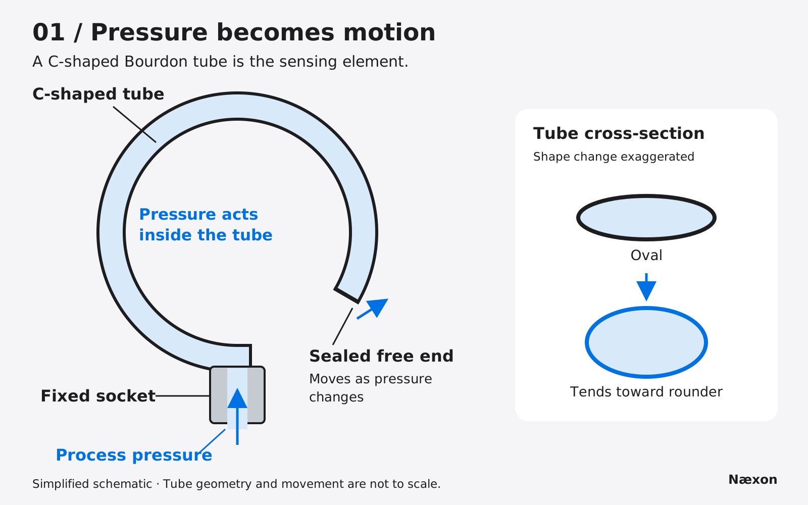
The threaded process connection leads into a passage in the socket or stem. In a directly connected gauge, that passage communicates with the inside of the Bourdon tube. One end of the tube is fixed at the socket. The opposite end is sealed and free to move.
The tube curves around much of the dial, but its cross-section is flattened or oval rather than round. When pressure inside rises relative to the surrounding case pressure, that cross-section tends to become rounder and the curved tube tends to uncurl. The free end shifts slightly. Within its designed elastic operating limits, the tube moves back as the pressure falls.
Process fluid does not have to flow continuously through the gauge to produce an indication. It transmits pressure into the tube’s enclosed internal space. On an instrument fitted with a diaphragm seal, the process is separated from the gauge by a diaphragm and pressure is transmitted through an instrument fill fluid instead. That arrangement must not be confused with liquid in the gauge case.
How a small movement becomes a large sweep
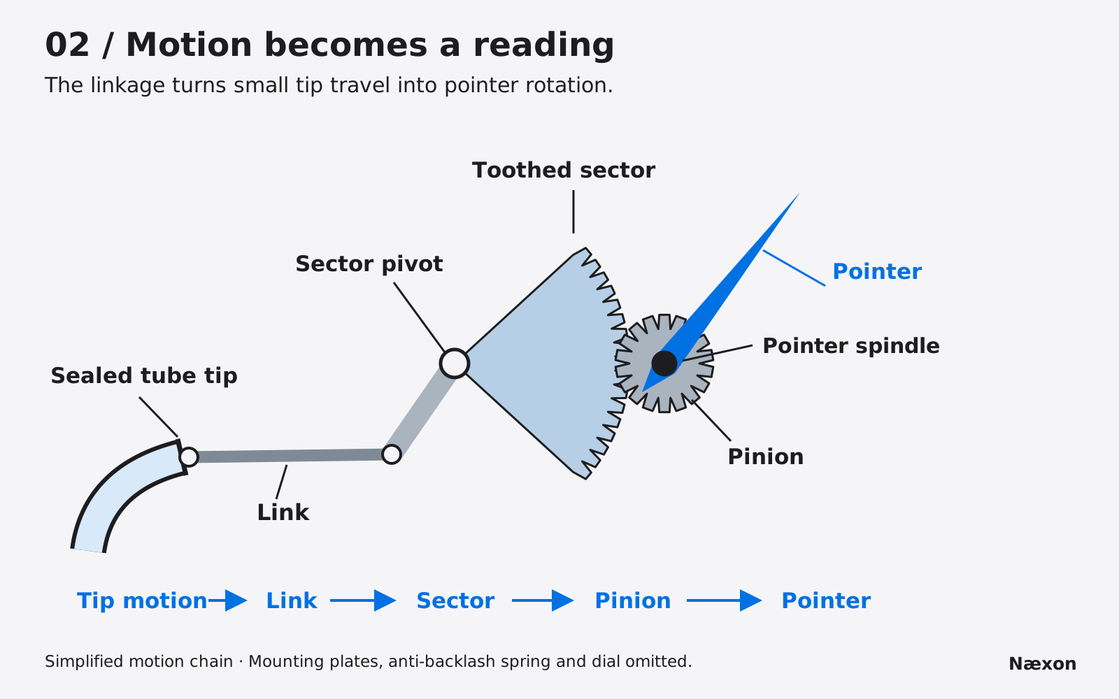
A link connects the moving tube tip to a lever on the movement. In a common geared design, this operates a toothed sector, also called a quadrant. The sector pivots and meshes with a small pinion on the pointer spindle. As the sector turns, the pinion rotates the spindle and pointer over the dial.
This linkage converts a small tube-tip displacement into an easily visible pointer sweep. Its geometry is part of the instrument’s design and calibration. A small spring is commonly used to keep the movement loaded against gear play. Exact layouts vary; some mechanical gauges use other movement arrangements.
The window protects the display, the dial supplies the scale, and the case supports and protects the assembly. Those visible parts do not measure pressure by themselves. If the pressure passage is blocked or the movement is damaged, an intact-looking dial can still display an incorrect value.
Why some gauges have liquid behind the window
The liquid visible behind the window of a liquid-filled gauge is case fill. Depending on the gauge and application, manufacturers use fluids such as glycerin or silicone. The fill surrounds the mechanism to damp vibration and pointer movement and help protect moving parts.
Case fill is separate from the process fluid inside an intact Bourdon tube. A visible air space is not, by itself, proof that the gauge has lost process pressure or needs topping up. Filling level and case venting are model-specific. Follow the manufacturer’s instructions rather than opening plugs or adding an arbitrary liquid.
Damping can make a pointer easier to read, but a steady pointer does not prove that pressure pulsations are harmless. Gauge selection, any approved restrictor or snubber, fluid compatibility and temperature limits still have to suit the service.
Know what zero means
A conventional gauge-pressure instrument compares pressure with the surrounding reference pressure, normally atmosphere in a properly vented arrangement. The abbreviation psig means pounds per square inch gauge. At zero psig, the measured pressure equals that atmospheric reference; it is not an absolute vacuum.
Absolute pressure is reported relative to a perfect vacuum and may be marked psia. A compound gauge can show both positive gauge pressure and pressure below atmosphere. A pressure unit such as psi alone does not fully identify the reference, so check the instrument documentation and specified service.
Do not treat a zero indication as proof that equipment is safe to open. A closed gauge valve, plugged connection, damaged instrument or isolated section can leave the pointer at zero while hazardous pressure exists elsewhere. Isolation and verification of released or restrained stored energy must follow the approved procedure. Never loosen a gauge or fitting to investigate a doubtful reading.
Other gauges can use different sensing elements
A diaphragm gauge uses a flexible membrane as its pressure-sensitive element instead of a curved tube. A digital pressure gauge uses a pressure sensor and electronics to turn its signal into a displayed number. Do not assume that an electronic display contains the linkage shown here, or that a diaphragm seal attached to a Bourdon gauge turns it into a diaphragm-element gauge. Identify the actual instrument before applying this explanation.
Read the scale before interpreting the process
First identify the gauge tag, measured location, units and range. Read the dial square-on to reduce parallax, which is the apparent shift in pointer position when viewed from an angle. Confirm which scale applies if the dial has more than one unit. Count the spaces between marks rather than counting the marks themselves.
For a paper example, imagine a 0–160 psig dial with numbered marks at 40 and 60. There are ten equal spaces between those marks. Each space represents (60 − 40) ÷ 10 = 2 psi. A pointer four spaces beyond 40 indicates 40 + (4 × 2) = 48 psig. The result is reasonably just below the midpoint of that interval.
This is an illustrative scale, not a specification for your gauge. Its graduation size does not establish its accuracy. A dial with fine marks may still have an accuracy specification based on full scale, span, reading or another stated basis. Use the actual specification and calibration status; do not add decimal places that the instrument cannot support.
What the reading can and cannot tell you
A gauge measures pressure at its sensing connection. It does not directly measure flow, prove that a valve is open, or establish pressure everywhere in a piping system. A blocked line can hold pressure with little or no flow. Elevation, restrictions and operating conditions can make two locations show different pressures.
When a reading seems wrong, begin with records and safe external observations. Confirm the tag and expected range, whether operations reports the process running, and whether the instrument is due for inspection or calibration. Record whether the pointer is steady, vibrating, sluggish or visibly off its expected position. Have an authorized person check isolation status and the installation under the site procedure.
Recognize faults without guessing at repairs
A rapidly oscillating pointer may reflect process pulsation, equipment vibration or both. A slow response may involve damping, a restricted passage, viscous media or other installation conditions. A reading that disagrees with another instrument may come from a genuine pressure difference, different reference conditions or an instrument problem. These are possibilities to investigate, not diagnoses from appearance alone.
A pointer that fails to return to its expected zero under verified reference conditions can indicate damage or loss of calibration. A leaking connection, damaged window, corroded case or pegged pointer also deserves prompt attention through the site’s reporting procedure. Do not tap the gauge or make adjustments merely to force an expected reading. Any manufacturer-specified reading method or adjustment belongs under the approved site procedure.
Calibration requires a suitable pressure reference, controlled conditions and an approved method performed by qualified personnel. Reading zero alone is not calibration. This lesson does not authorize removing the gauge, opening pressure boundaries or applying a test pressure.
Field Rules
- Identify the instrument and pressure reference before using its reading.
- Keep the process passage, seal fill and case fill distinct in your explanation.
- Use the actual scale and accuracy specification instead of assuming every dial is alike.
- Treat an unexpected indication as a reason to verify conditions, not permission to adjust equipment.
- Use the approved isolation and stored-energy procedure before any intrusive work.
Knowledge Check
- Why is the free end of a Bourdon tube sealed if pressure must enter the gauge?
- A liquid-filled gauge has a steady pointer. Does that establish that its process pressure is steady?
- Between 80 and 100 on an example dial are five equal spaces. What does the third space beyond 80 indicate?
- An installed gauge reads zero while its isolation status is unknown. What should happen before anyone loosens its connection?
Answers and explanations
- Pressure enters through the fixed socket end. The sealed opposite end contains the pressurized space and is free to deflect; the gauge does not need a through-flow outlet.
- No. Case fill damps movement. It can smooth the indication without eliminating the underlying pulsation or proving the instrument is suitable for it.
- Each space is (100 − 80) ÷ 5 = 4 units, so the indication is 92 in the dial’s stated unit. Check that unit before reporting the value.
- Stop intrusive work and use the approved isolation and stored-energy verification procedure through authorized personnel. A zero gauge indication by itself is insufficient.
Practical Exercise
On paper, draw a socket, a curved oval-section tube with a sealed free end, a link, a sector and a pinion carrying a pointer. Use one color for the pressure path and another for moving parts. The pressure path must stop inside the sealed tube; it must not run into the gears or case fill.
Then sketch the 40–60 interval used in the worked example with ten equal spaces and mark 48. Check your work by explaining the full chain aloud: pressure changes the tube’s shape, the tip moves the linkage, and the movement rotates the pointer. A correct sketch keeps the fixed end fixed and clearly separates fluid from mechanism.
Related learning
For applications where gauge selection and readings matter, continue with the hydrostatic testing field guide and the guide to pneumatic testing of industrial piping. For a related use of vacuum terminology, see how industrial piping is dried after hydrotesting. These describe broader processes; use the approved job procedure and qualified supervision for actual work.