Evening Edition • Primary trade: Electricians • Skill level: Intermediate • Classification: Troubleshooting • Estimated reading time: 11 minutes
What you’ll learn: how to read the symptom of a chattering motor contactor, use the control schematic to divide the problem, compare coil voltage with the exact device requirements, and know when the evidence points upstream rather than at the contactor itself.
The start button is pressed and the contactor pulls in, drops out, and pulls in again fast enough to sound like a rattle. The motor may bump, the enclosure may vibrate, and the crew’s first reaction is often, “The contactor is bad.” Sometimes it is. Often the contactor is only reacting to a control circuit that cannot keep its coil energized.
Chatter is rapid, repeated movement between the open and closed positions. It is not the same as the steady magnetic hum some AC devices produce while fully seated. Repeated opening and closing can increase mechanical wear and arcing at the main contacts, so the correct response is to stop cycling the starter and diagnose the cause—not keep pressing Start to see whether it clears.
What the coil is trying to do
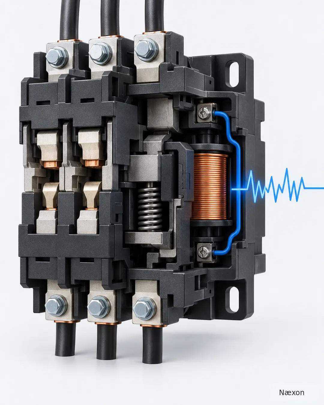
A contactor uses an electromagnetic coil to move an armature and close power contacts. During pull-in, the magnetic system must develop enough force to close and seat the armature. Once seated, the coil must remain energized strongly enough to hold it there. If control voltage falls outside the coil’s specified operating range, the armature may fail to seal or may release. When the voltage returns, it can pull in again, producing chatter.
Low or unstable control voltage is not the only cause. Poor contacts in the control circuit, a chattering input device, a mismatched coil, dirt or rust on magnetic pole faces, a damaged shading ring on an applicable AC design, misalignment, binding moving parts, incorrect mounting, or other mechanical damage can also prevent stable seating. The exact manufacturer instructions for that contactor govern inspection, service, and replacement.
The coil label matters. A replacement contactor frame can accept coils with different voltage or frequency ratings, and a coil that physically fits is not automatically electrically correct. Before measuring or replacing anything, record the complete device identification, coil marking, control supply, and schematic reference.
Read the holding circuit before opening the enclosure
In a common three-wire control circuit, the normally closed Stop and overload contacts are in series with the coil. Pressing the normally open Start button energizes coil M. An auxiliary M contact then closes around the Start button to create the holding, or seal-in, path. Releasing Start should not drop out the coil because the auxiliary path remains closed until Stop, an overload contact, or another series control device opens.
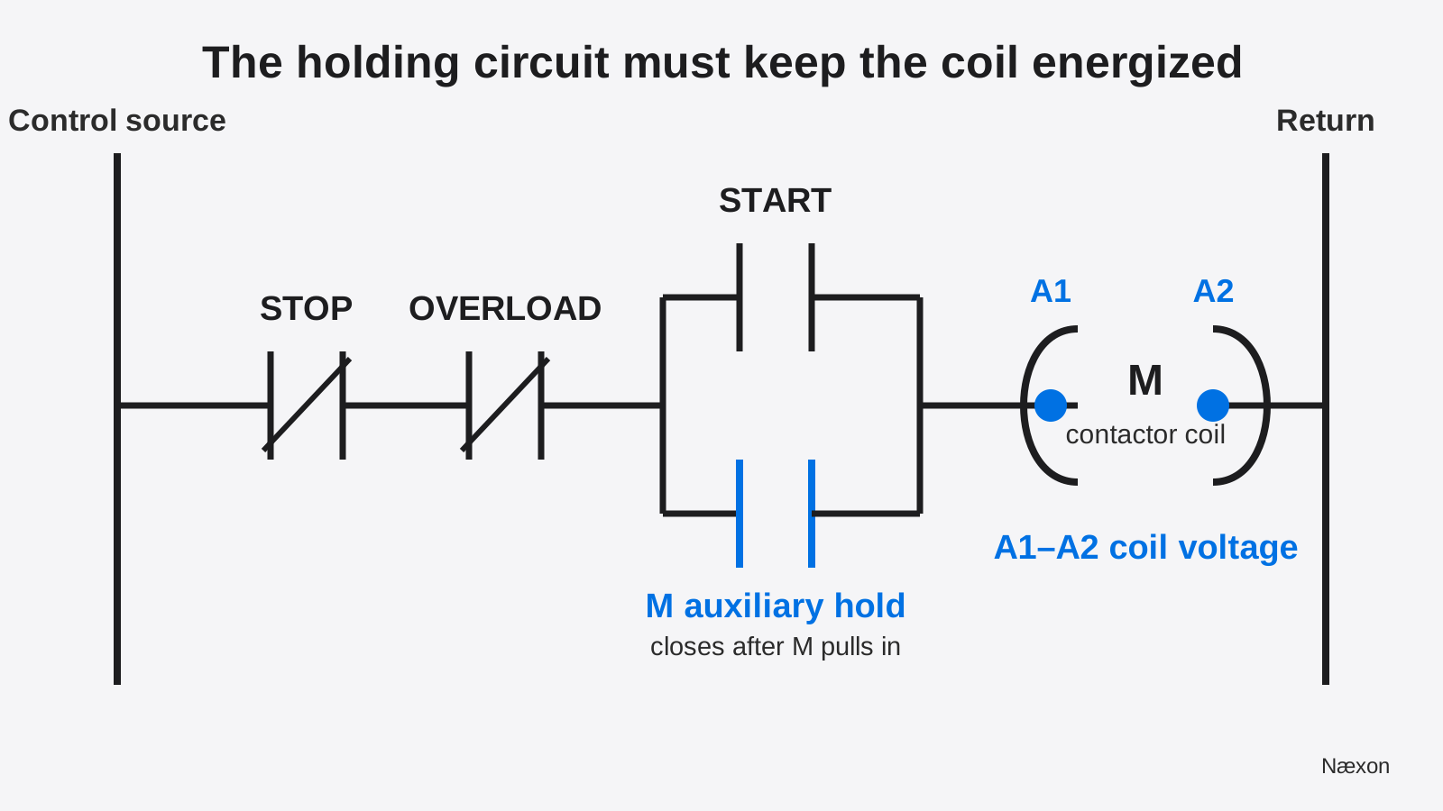
If the auxiliary contact does not close reliably, a series control contact has high resistance, or the control source sags during pickup, the coil voltage can collapse. The contactor releases, its auxiliary contact reopens, and the circuit attempts the sequence again if the command remains present. The sound may be at the contactor, but the initiating fault can be elsewhere on the rung.
The ladder in Figure 1 is educational, not a universal starter diagram. Real circuits may include permissives, emergency-stop devices, pressure or limit switches, interposing relays, PLC outputs, safety relays, local/remote selectors, or control transformers. Use the approved drawing for the exact equipment and confirm wire numbers and device tags in the field.
Safety boundary before troubleshooting
A push button, selector switch, PLC command, or interlock is not an energy-isolating device. When exposed electrical parts will be inspected, tightened, cleaned, or replaced, follow the site’s electrical safe-work and hazardous-energy-control procedures. Deenergize, isolate every applicable source, apply lockout/tagout, release stored energy, and have a qualified person verify the deenergized condition with appropriate test equipment.
Measuring coil voltage while the starter is commanded is an energized diagnostic task. It should be performed only by a qualified person when the employer’s electrical safety program permits and justifies the test, with the correct shock and arc-flash boundaries, PPE, test instrument rating, probes, and work method. This lesson does not authorize energized work. If the required condition cannot be established safely, stop and escalate.
A step-by-step troubleshooting method
- Capture the symptom and stop repeated attempts. Note whether the sound is rapid clicking or steady hum, whether the contactor fully seats, whether the motor bumps, which command initiated it, and whether other control devices flicker or reset.
- Get the correct documents. Identify the starter, coil rating, control voltage source, fuse or breaker, transformer if used, overload contact, auxiliary contacts, inputs, and the approved schematic. Confirm that the installed coil matches the design and frequency.
- Establish a deenergized condition for physical checks. Apply the approved isolation procedure and verify absence of voltage. Inspect for loose conductors, heat discoloration, damaged insulation, contamination, incorrect parts, a visibly obstructed armature, damaged springs, or mounting distortion. Do not file contacts, modify a spring, defeat an overload, or force the armature unless the manufacturer’s instructions specifically authorize the work.
- Trace the control path on the drawing. Follow the rung from the control source through Stop, overload, permissives, the Start/holding branch, and the coil return. Mark where a poor series contact or intermittent input could remove coil voltage.
- Plan the minimum diagnostic measurement. If an energized test is justified, measure across A1 and A2 while the command is present—not from one coil terminal to an assumed ground. Observe the voltage during pull-in and while the device attempts to hold. Compare it with the exact coil nameplate and manufacturer operating data.
- Divide the problem. Low or unstable voltage at A1–A2 points toward the source or upstream control path. Stable voltage within the exact coil specification points toward the installed coil, armature seating, contamination, binding, mounting, or internal damage.
- Correct only the verified cause. Repair or replace components under the approved procedure, using the specified parts, conductor preparation, and terminal torque. Reassemble guards and covers before the authorized return-to-service process.
- Verify the repair. Confirm stable operation through the required test sequence, record as-found and as-left observations, and stop if chatter, abnormal heat, odor, noise, or unexpected motor behavior remains.
Worked example: voltage at the coil tells the story
Consider an illustrative 120 V AC control circuit. The exact contactor documentation—not this example—defines the acceptable pickup and hold range. A qualified electrician, working under an approved energized diagnostic plan, measures 121.0 V AC at the control source while the Start command is present. At the same moment, the voltage across coil terminals A1–A2 fluctuates around 94.0 V AC, and the contactor chatters. The device’s actual documentation shows that this observed coil voltage is outside its required operating range.
Define VS = 121.0 V at the source and VC = 94.0 V at the coil. The voltage lost in the series control path is:
Vdrop = VS − VC = 121.0 V − 94.0 V = 27.0 V
Expressed as a percentage of the measured source voltage:
Percent drop = (27.0 V ÷ 121.0 V) × 100 = 22.3%
The numbers do not prove which upstream device is responsible, but they do show that replacing the contactor first would be an unsupported guess. After the circuit is deenergized, locked out, and verified, the electrician follows the schematic and finds a damaged series control contact. The approved replacement is installed. During the authorized functional test, the source remains 121.0 V and the coil measures 119.0 V while held.
The new path drop is 121.0 V − 119.0 V = 2.0 V, or (2.0 ÷ 121.0) × 100 = 1.65%. The contactor now pulls in once and remains seated, and 119.0 V is confirmed within that exact coil’s documented range. The independent check is behavioral and electrical: the device holds steadily and the measured coil voltage agrees with the control-source measurement after accounting for the smaller series drop.
This is a training example, not an acceptance limit. It does not establish a universal allowable voltage drop, coil tolerance, terminal torque, or replacement criterion. Those decisions belong to the equipment documentation, approved drawings, electrical safety program, and qualified supervision.
Use voltage to choose the branch
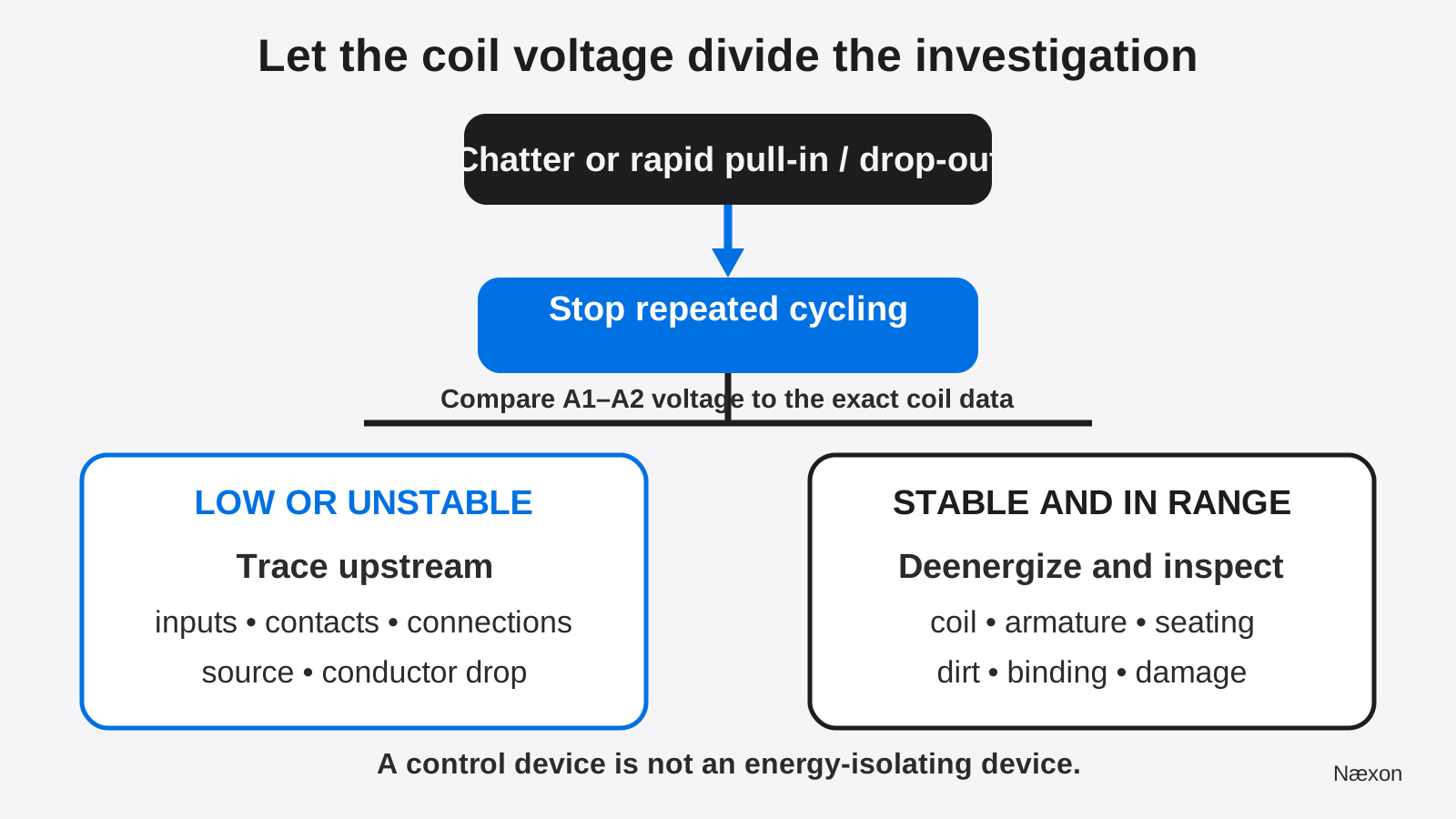
Low or unstable coil voltage. Check the control source under command, transformer loading, fuses and holders, wire terminations, long or undersized control conductors, Stop and overload contacts, selector and limit switches, interposing relays, auxiliary holding contact, PLC output or field interface, and any input that may itself be chattering. Use the schematic to move through the path rather than probing randomly.
Correct, stable coil voltage but chatter remains. Deenergize and inspect the exact coil and magnet assembly under manufacturer instructions. Look for incorrect coil identification, contamination on mating surfaces, rust, a damaged shading component where applicable, a distorted or misaligned armature, binding guides or springs, broken parts, or a mounting surface that amplifies vibration. Replace assemblies that are damaged or outside service limits; do not improvise repairs.
Common mistakes
The most common mistake is replacing the contactor because the noise is coming from it. A second is measuring the control transformer with no command present, seeing normal voltage, and assuming the coil receives the same voltage during pull-in. Voltage must be evaluated at the load and at the time the symptom occurs.
Other errors include measuring one coil terminal to ground instead of across A1–A2, assuming every coil in the same frame has the same rating, resetting an overload without finding why it opened, bypassing a permissive, using a control device as isolation, tightening energized terminals, repeatedly jogging a chattering starter, and cleaning or filing contact surfaces contrary to manufacturer instructions.
Do not confuse a chattering contactor with a motor overload problem. A tripped overload normally opens the coil circuit and prevents pickup; it is a protective response that requires investigation. The related lesson Why a Motor Trips on Startup follows that different fault path.
Field Rules
- Stop repeated cycling; chatter is not a harmless sound.
- Record the coil’s exact voltage and frequency marking before testing or replacing parts.
- Read the approved control schematic from source to coil return.
- Measure across A1–A2 during the commanded condition only under an approved energized test plan.
- Low or unstable coil voltage points upstream; stable in-range voltage points toward the contactor assembly.
- Push buttons, selectors, and interlocks do not provide energy isolation.
- Never invent voltage limits, terminal torque, or service procedures—use the exact manufacturer and project requirements.
Knowledge Check
- A contactor chatters, but the control transformer measures its nominal voltage with the Start command released. What is the next useful voltage observation, assuming an energized test is justified?
- Source voltage is 121.0 V and coil voltage while commanded is 94.0 V. What is the series-path drop and its percentage of source voltage?
- The voltage across A1–A2 remains stable and within the exact coil specification while chatter continues. Which branch of the investigation should come next?
- Why is replacing the contactor before measuring coil voltage an incomplete troubleshooting decision?
- Can the Stop button be used as the sole means of deenergizing the starter for tightening a coil terminal?
Answers
- Measure across A1–A2 during pull-in and the attempted hold, then compare that observation with the exact coil data. An unloaded source measurement can miss voltage lost through the energized control path.
- The drop is 27.0 V. The percentage is (27.0 ÷ 121.0) × 100 = 22.3%.
- Deenergize, lock out, verify, and inspect the coil and mechanical assembly under the manufacturer’s instructions. Stable in-range coil voltage makes an upstream voltage-loss explanation less likely.
- The sound location identifies the reacting device, not necessarily the initiating cause. A poor control contact, unstable input, conductor drop, or source problem can make a healthy contactor chatter.
- No. A Stop button is a control device, not an energy-isolating device. Follow the approved isolation, lockout/tagout, and verification procedure.
Practical Exercise
Using Figure 1 on paper, add one normally closed limit switch between the overload contact and the Start/holding branch. Then mark three voltage checks: the control source, the point immediately after the added limit switch, and A1–A2. Assume the source is 120.0 V, the point after the limit switch is 96.0 V while commanded, and A1–A2 is 95.5 V. The expected conclusion is that most of the loss occurs at or before the added limit switch, because only 0.5 V is lost from that point to the coil while 24.0 V is lost from source to the point after the switch. This is a drawing and calculation exercise only; do not perform energized measurements without qualification and an approved plan.
Related learning
Before working around exposed circuits, review the live–dead–live test and meter verification sequence. Strengthen drawing navigation with How to Read an Electrical One-Line Diagram, then practice unit discipline with Field Formulas for Electricians. These lessons support the safe reading and calculation skills used here without replacing the equipment-specific control schematic.