Morning Edition · Welders and boilermakers · Apprentice · Fundamentals · 9-minute read
What you will learn: Decode DCEP, DCEN, and AC; identify where the electrode and work leads connect; verify the required polarity from controlling documents; and recognize symptoms that justify stopping for a setup check.
A welder that ran smoothly on yesterday's job suddenly spits, wanders, or produces an arc that feels wrong. The amperage may be close and the leads may look secure, yet one small setup detail has changed: the electrode is connected to the wrong polarity for the process or consumable.
Polarity describes how a welding power source applies electrical potential across the arc. It affects arc behavior, heat distribution, oxide-cleaning action in some processes, deposition behavior, and how a particular electrode or wire performs. It is not a setting to choose from habit. The approved welding procedure specification (WPS), consumable classification and manufacturer data, and equipment instructions control the real job.
Start with the names, not the nicknames
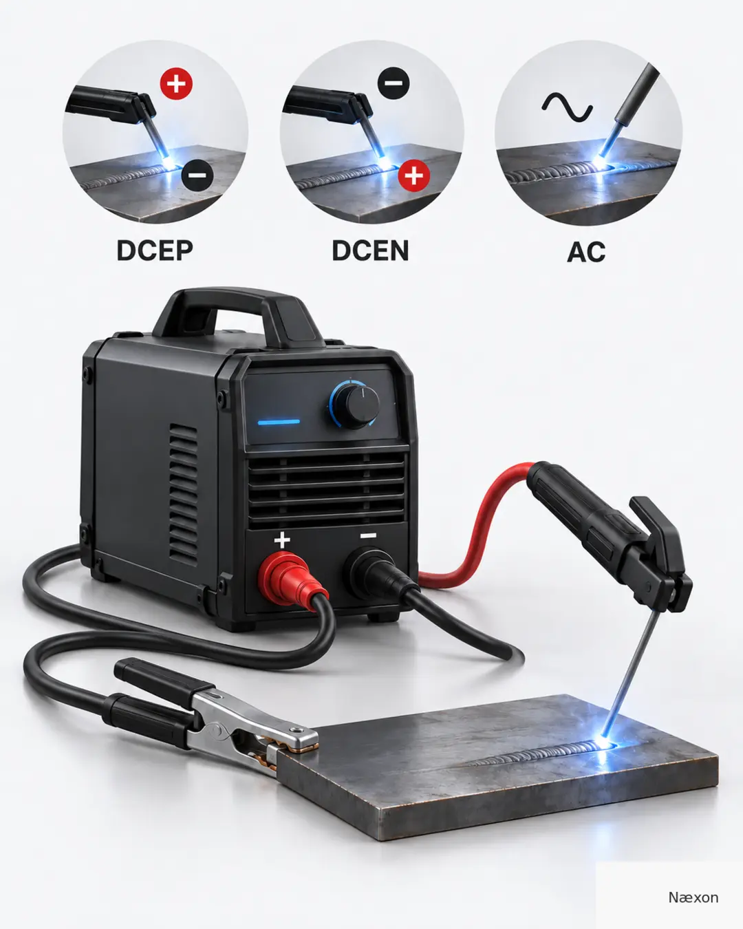
DCEP means direct current electrode positive. The electrode lead connects to the positive terminal, and the work lead connects to the negative terminal. DCEN means direct current electrode negative. The electrode lead connects to the negative terminal, and the work lead connects to the positive terminal.
Older terms may call DCEP “reverse polarity” and DCEN “straight polarity.” Those nicknames can be misunderstood, especially when crews use different habits. DCEP and DCEN are clearer because each name states the electrode's connection directly.
AC means alternating current. The electrical polarity reverses repeatedly during the cycle. On an AC-capable machine, connecting the leads does not create a fixed electrode-positive or electrode-negative condition in the same way as DC. Modern AC welding equipment may provide additional balance or waveform controls, but those settings are equipment- and procedure-specific.
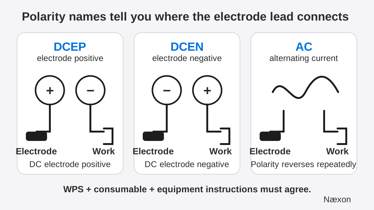
The clamp attached to the workpiece is properly called the work connection or work lead. Calling it a “ground” can hide an important distinction: the welding circuit's work connection is not automatically the same thing as the facility's protective earth grounding system.
Why the required polarity changes
There is no universal rule that one polarity is best for every welding process. The electrode coating, flux formulation, shielding method, base material, transfer mode, and power-source design all influence the required setup. Even within one process, two consumables that look similar may call for different polarity.
Common process patterns help with recognition, but they do not replace the instructions. Carbon-steel GTAW commonly uses DCEN. Solid-wire GMAW commonly uses DCEP. Many self-shielded flux-cored wires use DCEN, while other cored wires are designed for DCEP. SMAW electrodes may operate on DCEP, DCEN, AC, or more than one option depending on their classification and manufacturer data.
This is why “stick is always positive” or “flux core is always negative” are unsafe shortcuts. A familiar pattern is useful only as a prompt to verify. The WPS and the exact package or data sheet for the consumable settle the question.
Worked example: a spool change that changes polarity
Assume a training booth was last used with solid GMAW wire on DCEP. The next student installs a self-shielded flux-cored wire whose label specifies DCEN. The power source remains de-energized while connections are inspected. These are illustrative conditions; they do not replace the machine manual, shop procedure, or qualified supervision.
The required condition is written directly in the consumable information: DCEN. Break the name apart. “DC” requires direct-current mode. “EN” means electrode negative. Therefore, the gun or electrode lead must be connected to the negative output, and the work lead must be connected to the positive output, using the connection method specified by that machine.
An independent check reads the condition backward from the terminals: gun lead on negative equals electrode negative, so the arrangement is DCEN. A second check compares the WPS, consumable label, and machine diagram. All three must agree before welding.
The reasonableness check is procedural rather than mathematical: the setup changed because the consumable changed. If the machine is still arranged exactly as it was for the previous DCEP wire, the job has not yet been verified. No bead appearance can convert an incorrect documented setup into an approved one.
Assumption versus verification
The common incorrect approach is to copy yesterday's lead arrangement because the machine “always runs that way.” It fails when the process, electrode, wire, or WPS changes. You can recognize the mistake when nobody has read the current consumable label or traced the electrode lead to its terminal.
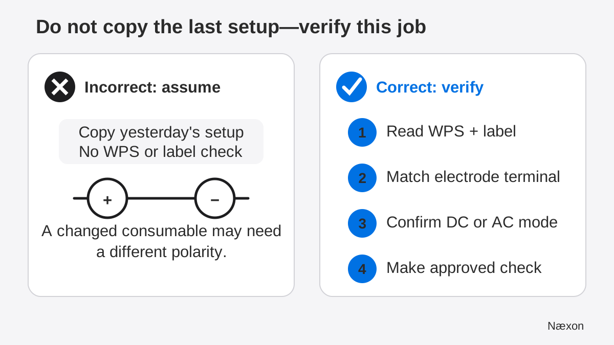
The correct result is a three-way match: the WPS or approved instruction names the polarity, the consumable information supports it, and the physical lead connections plus machine mode produce it. If one source disagrees, stop and resolve the discrepancy before striking an arc.
A practical polarity-checking method
- Identify the exact process and consumable. Record the process, electrode or wire classification, diameter, and any specified shielding arrangement. Do not rely on color, package shape, or memory.
- Read the controlling instruction. Find the polarity on the approved WPS, work instruction, or qualified training procedure. Then compare it with the exact consumable label or manufacturer data.
- Decode the abbreviation. For DCEP, electrode goes to positive. For DCEN, electrode goes to negative. For AC, confirm that the machine and procedure call for alternating-current mode.
- Make the equipment safe for inspection or change. Stop welding, de-energize as the manufacturer's instructions require, and follow the site's electrical-safety and lockout/tagout rules where they apply. Do not move leads under load.
- Trace both leads physically. Follow the electrode holder, torch, or gun lead to its output terminal. Follow the work lead to the other terminal. On wire feeders with internal polarity links, use the machine diagram rather than guessing from the front panel.
- Confirm machine mode and controls. Verify DC or AC selection and any process-specific connection shown by the manufacturer. Polarity is only one part of the approved setup.
- Perform the authorized check. Use the shop's approved setup or test-coupon procedure. If behavior is abnormal, stop and troubleshoot rather than compensating with unapproved setting changes.
Troubleshooting an arc that feels wrong
The wire stubs, spatters heavily, or the arc is unstable: first compare the actual wire classification and polarity with the WPS and package. Then inspect the specified shielding, contact tip, drive system, connections, and approved voltage and wire-feed settings. Polarity is a candidate, not an automatic diagnosis.
A GTAW tungsten overheats or degrades unusually fast: stop and confirm the selected mode, polarity, current range, tungsten type and size, preparation, shielding gas, and torch cooling requirements. Do not continue until the setup matches the approved procedure and equipment guidance.
The machine display says one thing but the leads suggest another: some equipment routes output through internal links, feeders, remote controls, or process selectors. Do not infer the actual circuit from a single cable color. Use the exact machine diagram and qualified maintenance support.
The WPS and consumable label appear to disagree: do not choose the option that runs better. Verify that the electrode classification and trade name are correct, check document revision and scope, quarantine an uncertain consumable if required, and escalate to welding supervision or quality control.
Stop immediately for damaged insulation, loose or overheated connectors, exposed conductors, electrical shock or tingling, unexpected arcing at connections, fire hazards, inadequate ventilation, or missing required PPE. Welding fumes, ultraviolet radiation, hot metal, sparks, and electric shock require the controls established for the work area.
Common mistakes
Reading the work lead instead of the electrode lead reverses the meaning of DCEP and DCEN. Using cable color as proof of polarity fails when leads have been moved or replaced. Treating every flux-cored wire as DCEN ignores wires designed for another polarity. Assuming every stick electrode runs DCEP ignores the electrode's actual classification. Changing amperage to “fix” a polarity problem masks the setup error instead of correcting it.
Another frequent error is changing connections while the power source is energized or welding output is active. Follow the equipment's shutdown instructions and site controls. Finally, do not judge conformance from a good-looking practice bead alone; approved production welding is governed by the qualified procedure and acceptance requirements.
Field Rules
- DCEP means electrode lead to positive; DCEN means electrode lead to negative.
- Use DCEP/DCEN language instead of relying on “straight” or “reverse” nicknames.
- Verify the exact WPS, consumable, and machine diagram every time the setup changes.
- Do not use cable color, yesterday's connections, or bead appearance as proof.
- De-energize and follow equipment and site controls before changing leads.
- When documents disagree or equipment condition is unsafe, stop and escalate.
Knowledge Check
- A WPS specifies DCEN. The electrode holder is on the positive terminal. What error do you identify?
- A student changes from solid wire to a self-shielded wire and leaves the machine on DCEP because “all wire welding is positive.” What is the correct first check?
- The front panel is labeled DC, but you cannot tell where an internal feeder link routes the gun lead. What should you do?
- An approved procedure calls for DCEP. Which terminal receives the work lead?
Answers
1. The setup is DCEP, not DCEN, because the electrode holder is positive. Stop, make the equipment safe, and correct the arrangement only under the approved instructions.
2. Read the exact wire classification and its manufacturer polarity requirement, then compare it with the current WPS and machine diagram. Self-shielded wires do not all share one universal polarity.
3. Do not guess from the panel or cable color. Use the exact feeder and power-source connection diagram or obtain qualified support before welding.
4. The work lead connects to the negative terminal. DCEP states that the electrode side is positive, leaving the work side negative.
Practical Exercise
On paper, draw two power-source terminals marked positive and negative. For Scenario A, the instruction reads “DCEP”; draw an electrode holder to positive and the work lead to negative. For Scenario B, the instruction reads “DCEN”; reverse the two leads. Under each sketch, write the full name and one verification source you would check. Your result is correct when the electrode terminal matches the final letter: P for positive, N for negative. Keep this exercise de-energized and paper-based; physical setup changes belong in supervised training under the machine instructions.
Related learning
If the process names are still unfamiliar, begin with the differences among MIG, TIG, and stick welding. Continue with how tungsten angle changes the GTAW arc, where polarity is already assumed correct and torch geometry becomes the next variable. For inspection practice, study using a bridge cam gauge for reinforcement and undercut; measurement verifies geometry but does not replace the WPS or governing acceptance criteria.