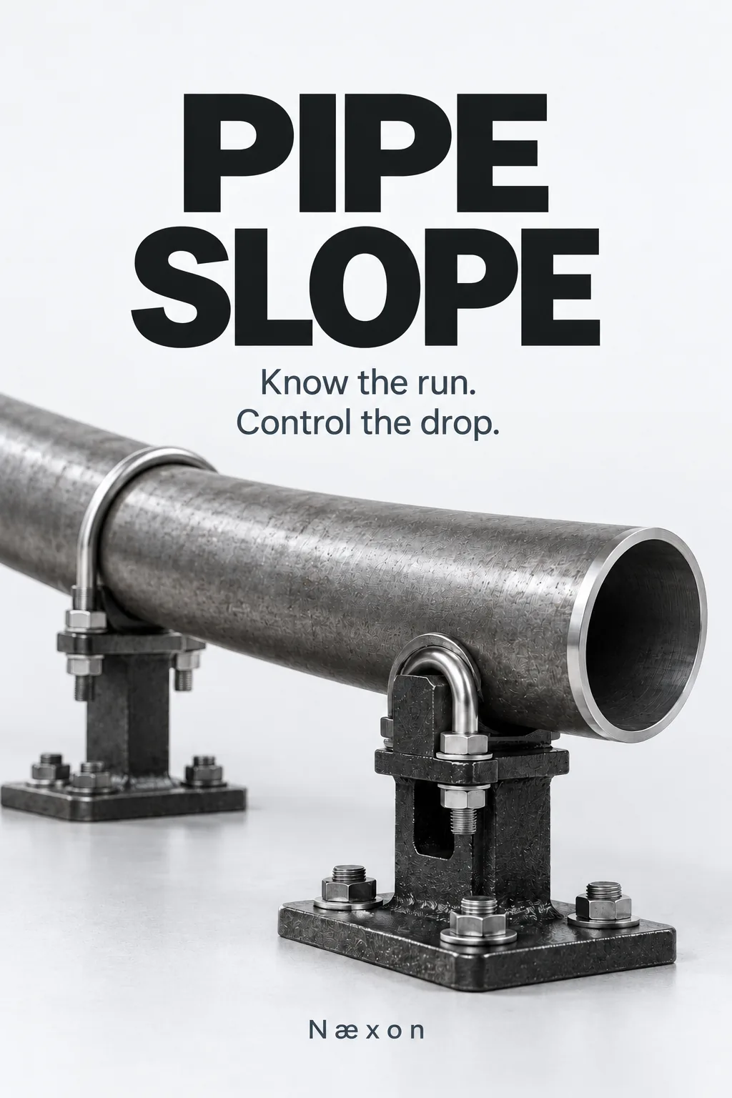
A drawing calls for a 1 percent fall. The fitter has a tape marked in feet and inches. The next connection is 30 feet away. Before cutting or moving a support, the crew needs one reliable answer: how much lower should that connection be?
The answer is 3.6 inches, provided the 30 feet is the horizontal run and the drawing requires a constant 1 percent fall over that run. Turning the drawing note into that number is straightforward. Keeping the reference points straight is what makes the number useful.
Start with the required slope
Slope belongs to the design. Use the approved drawing and project requirements to establish its magnitude, direction, reference elevation, and acceptance tolerance. Do not choose a slope because a similar-looking line used it on another job.
Drainage is one reason slope matters. In steam distribution, for example, condensate needs an intended route to the drainage points. That does not make one steam-system recommendation a universal rule for every process, drain, or condensate line.
For the calculations below, slope means vertical elevation change divided by horizontal run. The pipe length measured along the inclined centerline is a different dimension. A shallow slope makes the two lengths look almost identical, but they are not interchangeable definitions.
Translate the drawing note
A 1 percent slope means 1 unit of vertical change for every 100 units of horizontal run. Use the same units in the numerator and denominator.
Slope as a decimal = percent ÷ 100
Fall = horizontal run × slope as a decimal
For 1 percent, the decimal is 0.01. Over 12 horizontal inches, the fall is 12 × 0.01 = 0.12 inch. So 1 percent equals 0.12 inch per foot.
Now compare that with 1/8 inch per foot:
0.125 ÷ 12 × 100 = 1.0417 percent, approximately.
The two values are close, but they are not equal. Over a 100-foot horizontal run, 1 percent produces 12 inches of fall; 1/8 inch per foot produces 12.5 inches. That half-inch difference can matter at a fixed connection. Keep the specified value through the calculation and round only to the precision the project permits.
A ratio written as 1:100 also needs a definition. When the drawing means 1 vertical to 100 horizontal, it equals 1 percent. Do not assume an unlabeled ratio or arrow tells you its direction.
Work the elevation from one datum
Consider an illustrative straight run with these drawing values:
- Starting centerline elevation: 104 feet 6 inches
- Horizontal distance to the next connection: 30 feet
- Required fall toward that connection: 1 percent
Convert the run: 30 × 12 = 360 inches.
Calculate the fall: 360 × 0.01 = 3.6 inches.
Subtract it from the starting elevation: 104 feet 6 inches − 3.6 inches = 104 feet 2.4 inches.
Check the result backward. The elevation difference is 3.6 inches. Dividing by 360 inches gives 0.01, or 1 percent. The destination is lower, which agrees with the stated fall direction.
At a point 12 horizontal feet from the start, the required fall is 144 × 0.01 = 1.44 inches. The centerline elevation there is 104 feet 4.56 inches. Calculate each checkpoint from the same starting datum rather than repeatedly subtracting rounded intermediate values.
These figures are a math exercise. They do not specify a real line's slope or installation tolerance.
Compare the same physical reference
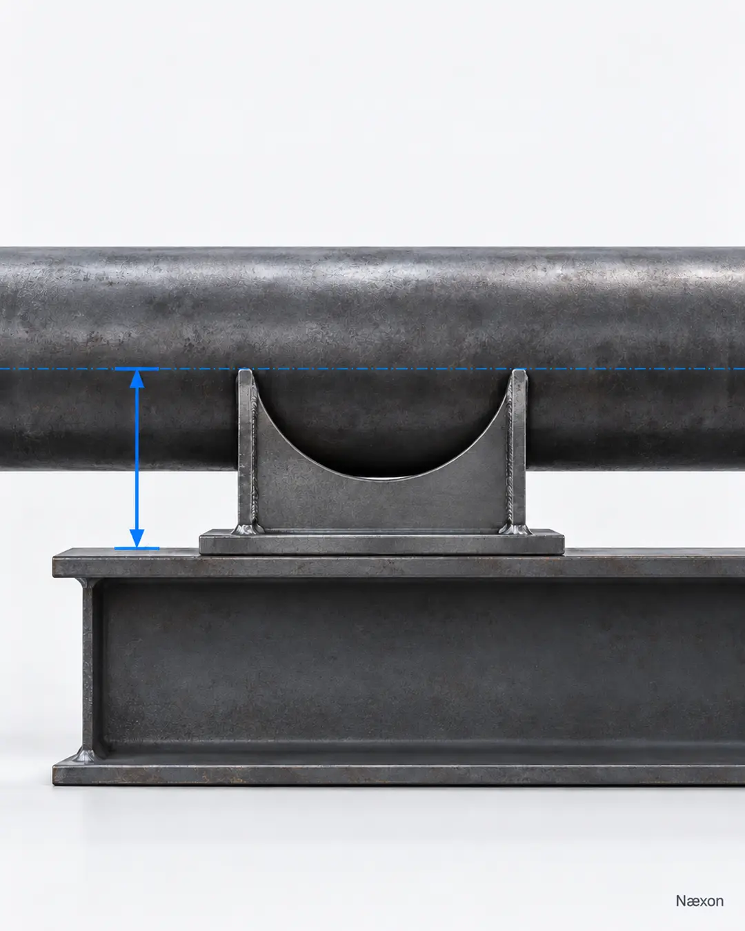
A centerline elevation cannot be checked directly against a bottom-of-pipe mark without a conversion. For round pipe, bottom-of-pipe elevation equals centerline elevation minus half the actual outside diameter. Nominal pipe size is not the outside diameter. A shoe, insulation layer, or support detail introduces additional geometry.
Use the project component data and, where helpful, the Næxon In-dex dimensional reference to identify the dimension that needs verification. Confirm critical values against the approved component and drawing information.
The related pipe penetration layout guide explains why the elevation at a wall must be calculated at that wall's location.
Check the installed route
Verify the actual slope using the project's accepted survey or measurement method. A level bubble by itself does not establish a specified numerical grade. Confirm instrument setup, reference surfaces, units, and direction before accepting readings.
Check intermediate locations as well as the endpoints. Two correct end elevations do not prove that the pipe has no local sag or reverse slope between them. Record deviations and resolve them through the approved process; do not force a spool or change an engineered support to hide a mismatch.
Before signing off, identify the drawing revision, datum, horizontal stations, required elevations, measured elevations, and applicable tolerance. That record lets the next crew understand exactly what was checked.
Quick check
A drawing specifies a 0.5 percent fall across 24 horizontal feet. How far does the line fall?
24 × 12 × 0.005 = 1.44 inches.
If the calculation gives 12 inches or 144 inches, stop and find the unit error. A correct slope calculation always preserves the units, the direction, and the reference point.
Related measurement lessons
For another example of keeping measurement units consistent, see welding arc energy and travel speed calculations.