Morning Edition · Instrumentation and controls technicians · Apprentice · Fundamentals · 9-minute read
What you will learn: Explain how lead-wire resistance affects an RTD reading, distinguish 2-wire, 3-wire, and 4-wire measurement methods, estimate a simple Pt100 lead-error example, and recognize when the instrument diagram must control the wiring.
A temperature point that has been steady for months is suddenly several degrees high after a cable replacement. The process has not changed, the sensor is still installed, and the input channel is healthy. One of the first questions should be simple: is the RTD connected with the same measurement method the input is configured to use?
An RTD, or resistance temperature detector, changes resistance with temperature. That makes the resistance of every conductor between the sensing element and the measuring instrument part of the measurement problem. This lesson focuses on that wiring effect. It does not set a calibration tolerance or authorize work on energized process equipment. Approved loop drawings, the sensor data, the input-module or transmitter manual, site procedures, and qualified supervision govern actual work.
If RTDs are new to you, begin with the broader overview of what instrumentation and controls technicians measure and maintain. Here, the scope is narrower: understanding what the extra RTD wires do.
The sensor resistance is only part of the circuit
A common industrial platinum RTD is the Pt100. Its nominal resistance is 100 ohms at 0°C. For the common IEC 60751 curve with alpha approximately 0.00385 ohm per ohm per degree Celsius, the average resistance change from 0°C to 100°C is about 0.385 ohm per degree Celsius. The actual curve is nonlinear, so instruments use the configured RTD curve rather than one constant slope over the full range.
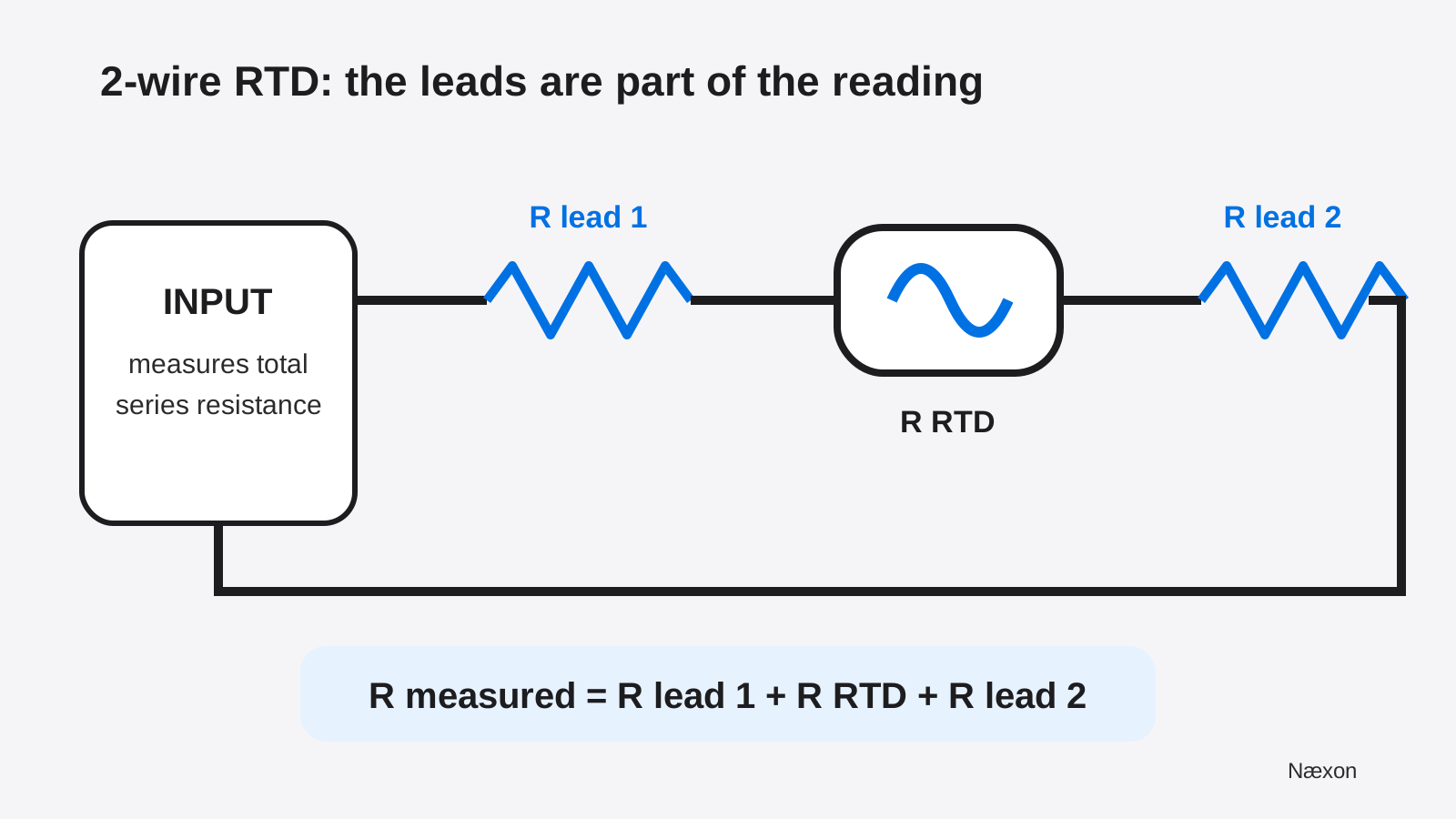
In a 2-wire connection, the measuring current passes through one lead, the sensing element, and the return lead. The instrument therefore sees the RTD resistance plus both lead resistances. It cannot separate those series terms from the sensor term. Longer or smaller conductors generally have more resistance, and copper lead resistance also changes with temperature.
Write the simplified 2-wire measurement as Rmeasured = Rlead 1 + RRTD + Rlead 2. Figure 1 shows why a zero-resistance assumption can make a healthy Pt100 appear hotter than it is.
Worked example: what 2 ohms can look like
Assume a Pt100 is at 0°C and has exactly 100.00 ohms in this illustrative exercise. The two field conductors contribute a total of 2.00 ohms: 1.00 ohm in the outgoing lead and 1.00 ohm in the return. Assume the input is using a 2-wire method and no separate lead compensation is applied.
Define R0 = 100.00 Ω, RL,total = 2.00 Ω, and the near-zero average sensitivity S ≈ 0.385 Ω/°C. The input sees:
Rmeasured = 100.00 Ω + 2.00 Ω = 102.00 Ω.
For a first-order estimate near 0°C, divide the added resistance by the approximate sensitivity:
Estimated temperature error ≈ 2.00 Ω ÷ 0.385 Ω/°C = 5.19°C.
The ohms cancel, leaving degrees Celsius. Rounded to one decimal place, the simple estimate is about +5.2°C. It is positive because the extra resistance makes a standard platinum RTD appear warmer. Independently checking the result in reverse, 5.19°C × 0.385 Ω/°C ≈ 2.00 Ω.
The answer is reasonable because a Pt100 changes by less than half an ohm per degree near 0°C; two extra ohms must represent several degrees, not a few tenths. This is a teaching estimate, not an acceptance calculation. A real instrument applies its configured curve—often the Callendar–Van Dusen relationship—and actual sensor class, input accuracy, self-heating, reference uncertainty, wiring, and procedure also matter.
What the third and fourth wires change
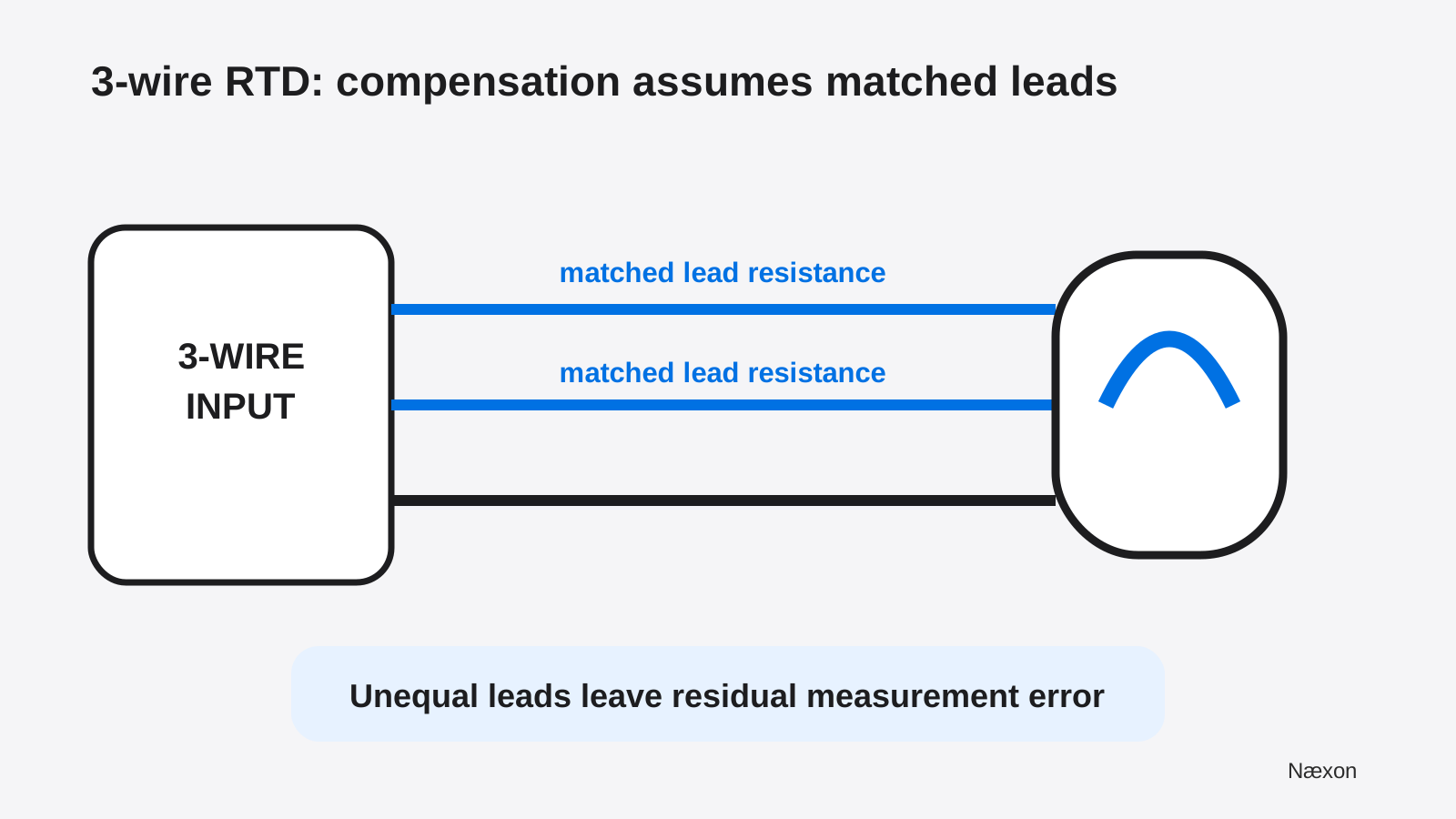
A 3-wire RTD gives the instrument an additional conductor so a compatible input can estimate and compensate for lead resistance. The exact circuit varies by instrument. A common method assumes the relevant leads have equal, or closely matched, resistance. If those leads are the same material, length, gauge, routing, and temperature, the assumption can be useful. If they are mismatched, a residual error remains.
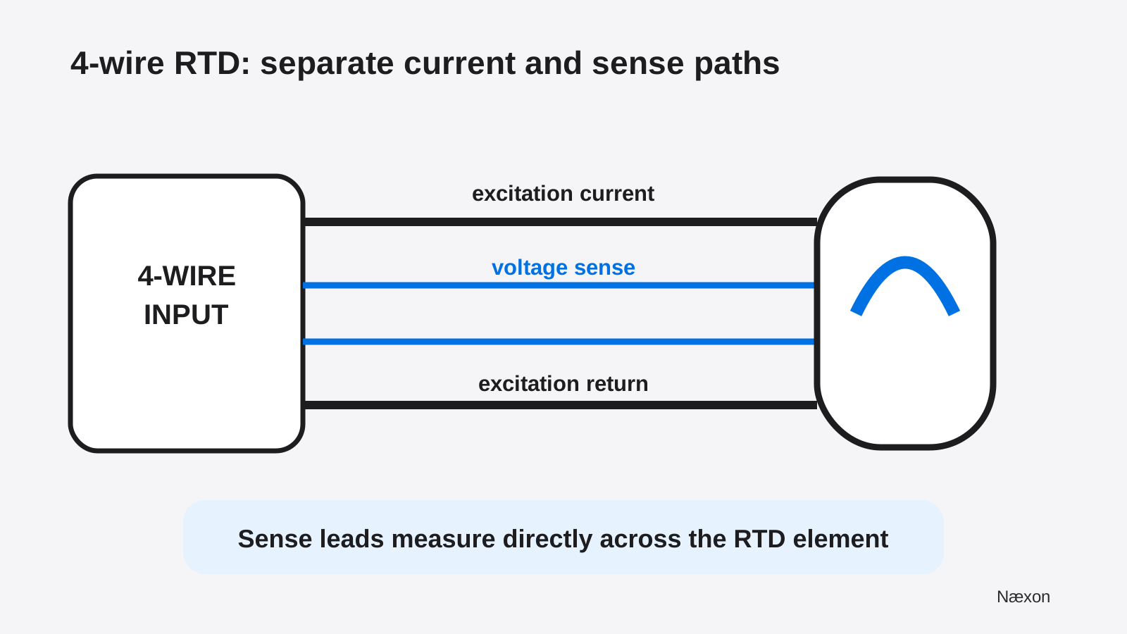
A 4-wire measurement uses one pair of conductors to carry excitation current and a separate pair to sense voltage across the RTD element. Because the voltage-sensing input draws very little current, the voltage drop in those sense leads is negligible for the measurement. The instrument can calculate the element resistance without including the current-lead drops.
More wires do not automatically make a loop correct. A 3-wire sensor landed on terminals intended for a 2-wire configuration may still be measured as a 2-wire device. A 4-wire sensor with one conductor omitted can behave as a 3-wire device only when the instrument documentation permits that arrangement. Wire colors are helpful clues, not universal terminal instructions; verify the sensor and module diagrams.
A practical identification and checking method
- Establish the safe work state. Follow isolation, access, and hazardous-area requirements. Do not disconnect a live protective or control function just to identify conductors.
- Read the documents first. Confirm the loop drawing, sensor type, nominal resistance, alpha or curve, number of conductors, input-channel configuration, and exact terminal diagram.
- Inspect the whole path. Include the sensor head, extension cable, junction boxes, barriers, marshalling, transmitter, and input module. A 3-wire sensor can be defeated by a 2-wire field extension.
- Identify paired conductors. With the circuit safely isolated under the approved procedure, resistance checks can help identify which conductors terminate on the same side of the sensing element. Use the manufacturer’s method; do not infer a universal color code.
- Compare like with like. Confirm that the physical sensor wiring, extension wiring, and configured input method agree. Record units and conductor identities before moving a wire.
- Restore and verify. Reconnect to the approved diagram, complete the required checks, and compare the returned indication with an appropriate reference or process condition under the governing procedure.
This sequence supports troubleshooting; it is not a substitute for a calibration. The pressure-transmitter calibration lesson reinforces the same boundary: comparison data support a decision only when the reference, method, and acceptance requirements are defined.
Troubleshooting patterns
If a point reads high after a long cable run is added, verify whether the channel is actually configured for the sensor’s wire count and curve. In a 2-wire Pt100 circuit, additional series resistance is a direct suspect. Do not “trim out” the symptom until the wiring method and configuration are known.
If a 3-wire point shifts after one conductor is repaired or replaced, compare the construction and route of all compensation leads. A splice, different gauge, loose terminal, corroded connection, or temperature gradient can upset the matched-resistance assumption. The symptom may change with ambient temperature if one lead experiences a different environment.
If the indication is open, overrange, or erratic, look beyond compensation theory. Broken conductors, intermittent terminals, moisture, poor shield termination, an incorrect sensor type, and input faults can produce similar symptoms. Stop and escalate when the circuit serves a trip, interlock, or other safety function, when hazardous energy controls are unclear, or when the approved drawing and installed wiring disagree.
If a local temperature transmitter converts the RTD measurement to 4–20 mA near the sensor, the long home-run cable carries the current signal rather than the raw RTD resistance. Lead-wire effects still matter between the RTD and transmitter, but the current loop has a different measurement principle. Continue with how 4–20 mA instrument loops work to follow that signal downstream.
Common mistakes and Field Rules
A common mistake is treating “three wires present” as proof that three-wire compensation is active. The channel must support the method, the conductors must be landed correctly, and the configuration must match. Another is assuming equal wire colors always identify the same terminal relationship. Manufacturers often use paired colors, but the device documentation is the authority.
It is also wrong to call the 5.2°C estimate a universal correction. It depends on the stated 2.00-ohm total, the Pt100 curve, and the near-zero approximation. Actual correction or acceptance belongs to the approved procedure and instrument system.
- Count the conductors, then verify the terminal diagram and channel configuration.
- Treat lead resistance as part of a 2-wire RTD measurement.
- Remember that 3-wire compensation relies on the supported method and matched leads.
- Use 4-wire sensing when the specified system requires the strongest separation of lead drops from element resistance.
- Record the wiring method with the measured value; a number without its measurement path is incomplete.
Knowledge Check
- A Pt100 at 0°C is connected in a 2-wire circuit with 0.75 Ω in each lead. What total resistance does the input see before other errors?
- A 3-wire point reads correctly in cool weather but drifts after one extension conductor is rerouted through a hot area. What assumption should be checked first?
- A sensor has four conductors, but the channel is configured and landed as 2-wire. Does the conductor count alone eliminate lead error?
- Why do voltage-sense leads in a 4-wire measurement have little influence on the calculated element resistance?
Answers and explanations
1. The input sees 100.00 Ω + 0.75 Ω + 0.75 Ω = 101.50 Ω. The two lead resistances are in series with the element. 2. Check the matched-lead assumption and the approved routing. Different conductor temperature can create unequal resistance and residual error. 3. No. The measurement method and landing determine what is compensated; unused conductors do not cancel resistance. 4. A high-impedance sense input draws very little current, so its lead voltage drops are negligible while it measures voltage directly across the element terminals.
Practical Exercise
On paper, draw a Pt100 with 1.20 Ω in one 2-wire lead and 0.80 Ω in the other. At an illustrative 0°C element resistance of 100.00 Ω, calculate the resistance seen by a 2-wire input and estimate the near-zero temperature error using 0.385 Ω/°C. Then redraw the sensor as a 3-wire installation and circle the two leads whose resistance matching the instrument depends on according to its terminal diagram.
Expected result for the 2-wire arithmetic: Rmeasured = 100.00 Ω + 1.20 Ω + 0.80 Ω = 102.00 Ω, and the first-order error estimate is 2.00 Ω ÷ 0.385 Ω/°C ≈ +5.2°C. Your 3-wire drawing is correct only if it follows a specific reviewed input diagram; there is no universal terminal assignment to guess from this exercise.
For the next step in measurement judgment, review how repeatability differs from agreement with a reference. A stable RTD value can repeat perfectly and still be wrong if the measurement path includes an unrecognized lead-resistance error.