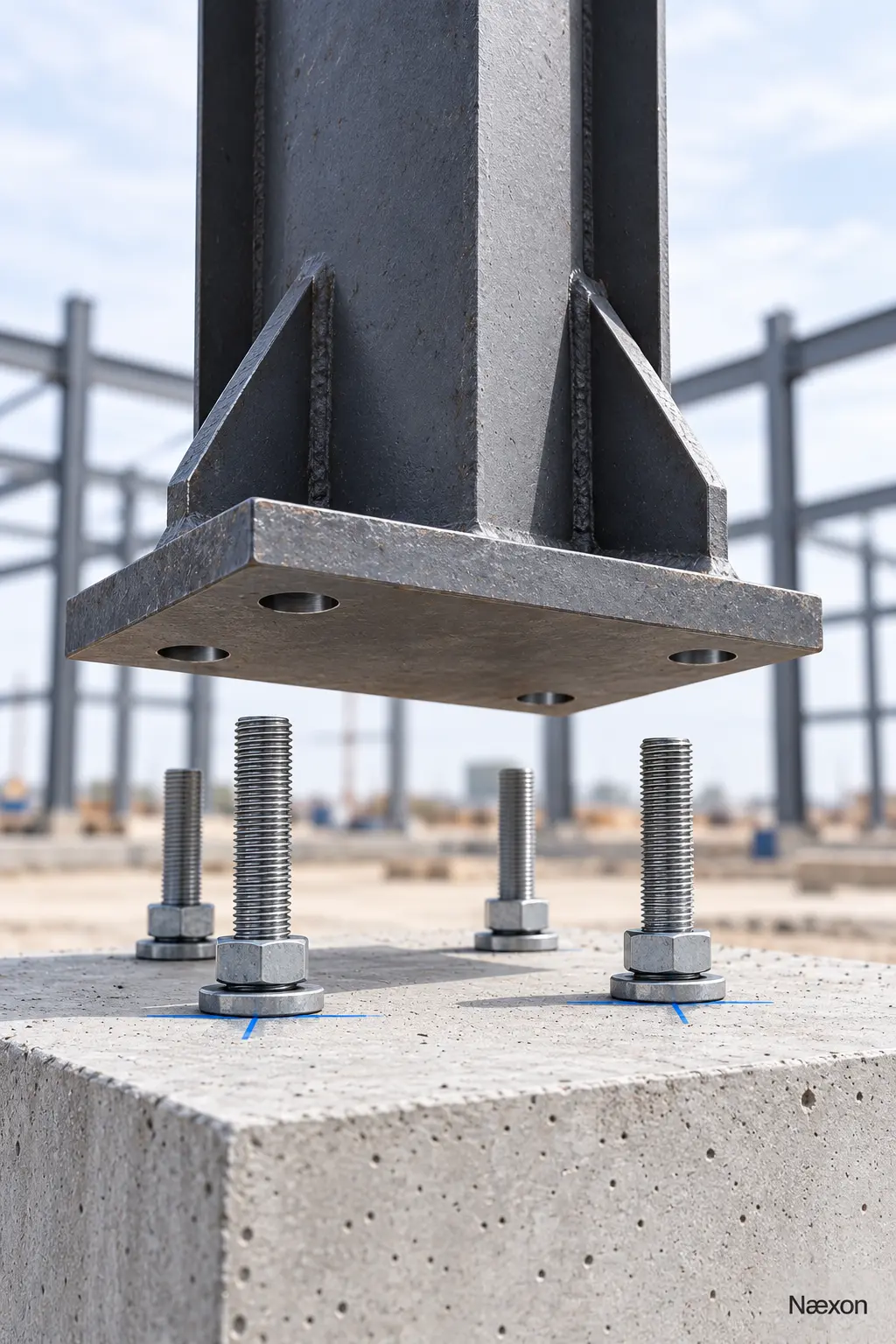
Evening Edition · Ironworkers · Intermediate · Print Reading · 9-minute read
What you will learn: Read a four-rod column pattern from approved drawings, check center-to-center spacing and diagonals, confirm orientation to gridlines, and recognize when the right dimensions are turned the wrong way.
The column is on the hook, the base plate is coming down, and one corner will not clear an anchor rod. That is the wrong time to discover that a rectangular rod pattern is rotated, shifted, or measured from the wrong reference. Forcing the plate, striking the rods, or enlarging a hole in the moment can convert a layout problem into an engineered repair.
This lesson is about the pre-set check: confirming the physical anchor-rod pattern against the approved erection and foundation information before the column is released for setting. It does not establish project tolerances or authorize field modification. Hole sizes, rod locations, base-plate details, grout space, leveling method, and acceptance limits come from the approved drawings, specifications, erection plan, and project structural engineer.
If the piece identity or orientation is uncertain, first review how erection marks connect a steel member to the plan. A correct survey on the wrong column or wrong grid intersection is still wrong.
Start with centers, axes, and orientation
An anchor-rod pattern is normally understood by the locations of the rod centerlines. A rectangular four-rod group has a long spacing, a short spacing, and two diagonals. Those measurements describe the shape, but they do not by themselves prove that the pattern is aimed in the correct direction or centered at the correct location.
Separate three questions. First, is the pattern the correct size? Second, is that pattern oriented correctly to the building grid or column axes? Third, is the entire pattern centered where the approved documents place it? A crew can answer the first question correctly and still miss the other two.
Measure rod centers, not the changing outside edges of threads, nuts, sleeves, or protective caps. When direct center measurement is awkward, use a consistent method approved by the crew—such as measuring the same outside face on rods of verified equal diameter and converting to center distance. Record what was actually measured rather than writing a center-to-center value that was never established.
Use the diagonal as an independent shape check
For a true rectangle, each diagonal is calculated from the long and short center-to-center spacings by the Pythagorean relationship: D = √(X² + Y²). The two measured diagonals should also agree with each other within the project’s accepted survey and fabrication limits. Equal diagonals are evidence that the four centers form a rectangle; they are not permission to invent a tolerance.
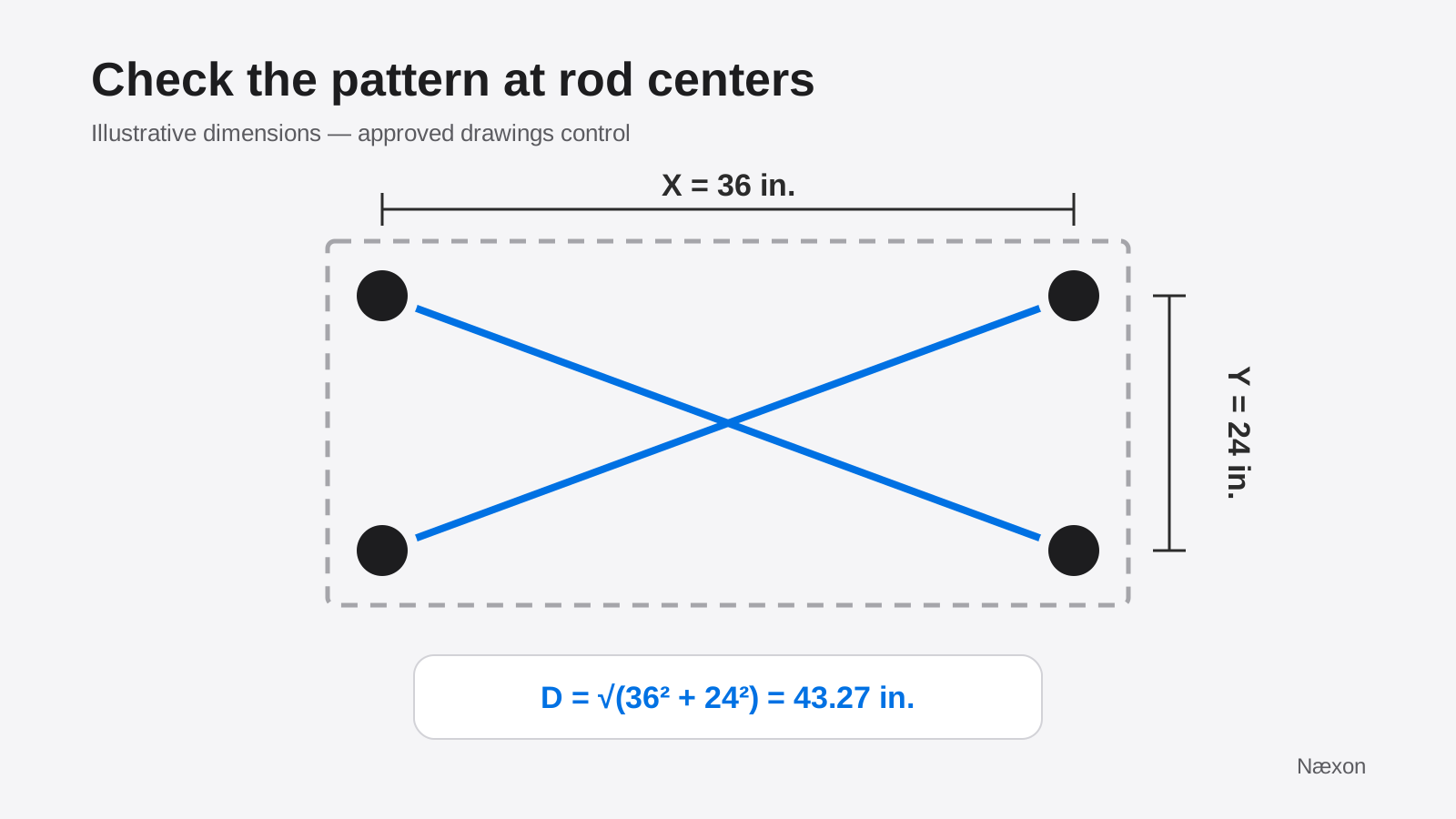
The diagonal check is valuable because two side dimensions alone can hide a parallelogram. A pattern may still measure 36 inches across and 24 inches along adjacent sides while one corner has shifted. The diagonals will separate: one becomes longer and the other shorter. That is a reason to stop and recheck the survey, not a reason to select the diagonal that looks better.
Worked example: a 36-inch by 24-inch pattern
Assume an illustrative drawing calls for a rectangular four-rod pattern with X = 36.00 inches and Y = 24.00 inches, measured center to center. These values are training dimensions only. The project drawing and survey criteria control a real base.
Define D as the theoretical diagonal. Keep the units throughout:
D = √(X² + Y²) = √[(36.00 in.)² + (24.00 in.)²]
D = √(1,296.00 in.² + 576.00 in.²) = √1,872.00 in.² = 43.2666 in.
Rounded to the nearest hundredth for this paper exercise, D = 43.27 inches. A calculator check reverses the operation: 43.2666² is approximately 1,872, while 36² + 24² is exactly 1,872. The units also check because the square root of square inches returns inches.
Now suppose the field notes show the two side spacings at the intended values, but the diagonals are 42.9 inches and 43.6 inches. Do not average those numbers into an apparently good diagonal. Their separation indicates that the four centers are not behaving as the intended rectangle, or that the measurement method was inconsistent. Recheck endpoints, tape condition, rod identification, obstructions, and the survey setup before escalating the actual readings.
A reasonableness check helps catch calculator errors. A 36-by-24 rectangle must have a diagonal longer than 36 inches but shorter than 60 inches, the sum of the two sides. A reported diagonal of 30 inches or 62 inches cannot fit this geometry.
Why correct dimensions can still be rotated
A rectangular pattern can have the correct 36-inch and 24-inch spacings and equal 43.27-inch diagonals yet still be rotated 90 degrees relative to the column orientation. The rectangle is correct as a shape, but the long axis points north–south when the drawing requires east–west. If the base plate is not square, or the column web and flange orientation matters, the holes will not land as intended.
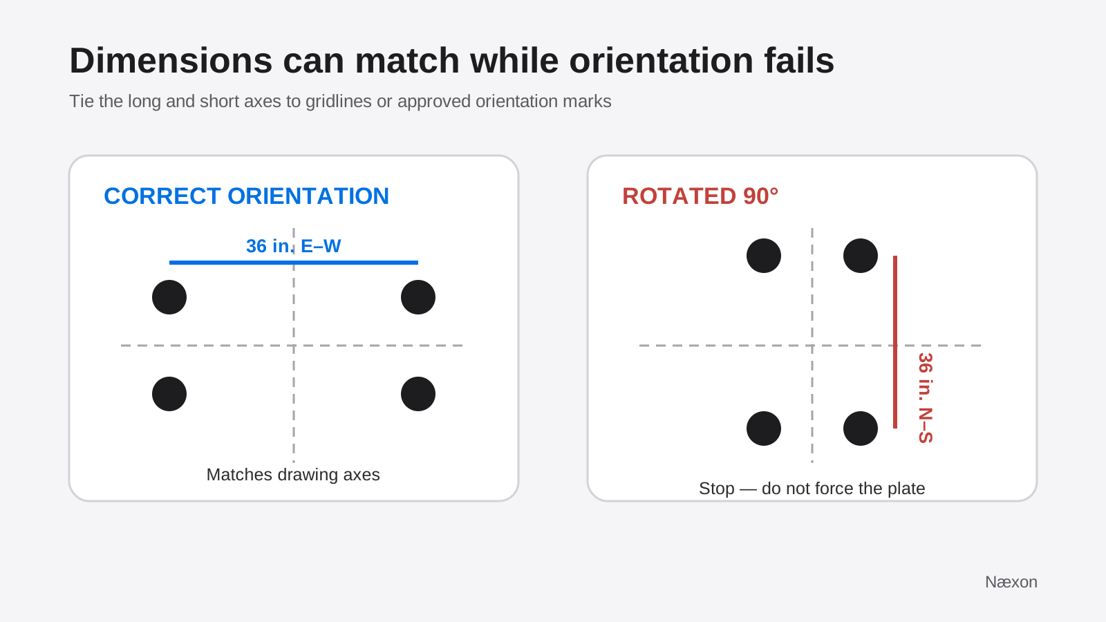
That is why a field sketch should include gridline names, north or another approved orientation reference, the column mark, and which dimension follows each axis. A bare rectangle labeled 36 by 24 is incomplete if it does not show which way the rectangle belongs.
A disciplined pre-set check
- Confirm identity. Match the grid intersection, foundation or pier mark, column mark, and base-plate detail to the current approved documents.
- Confirm the reference system. Identify the building gridlines, column axes, centerline marks, elevation reference, and any approved north or orientation symbol.
- Inspect without altering. Note damaged threads, bent-looking rods, missing hardware, sleeves, caps, contamination, and previous repairs. Do not straighten, heat, cut, weld, or relocate a rod.
- Measure center-to-center. Record the long spacing, short spacing, both diagonals, and pattern position relative to the approved centerlines. Use one consistent measurement method.
- Check orientation. State which field dimension follows each grid axis. Compare the base-plate hole pattern and column web/flange direction with the erection information.
- Escalate discrepancies. Mark the base as hold or follow the project’s control process. Report actual readings, references, and photos or survey data where authorized.
The column should not become the measuring tool. Lowering a suspended member repeatedly to see which hole binds exposes the crew to unnecessary suspended-load time and gives poor diagnostic information. The pre-set record should tell the team whether the pattern is ready before the member enters the pinch-point zone.
Do not turn a mismatch into a field modification
A common incorrect approach is to force the plate over a rod, beat a rod sideways, cut a slot, or enlarge a base-plate hole without an approved disposition. That can damage threads, change load paths, hide the original survey evidence, and create work that requires engineering review. The safe corrective principle is to stop, preserve the measurements, protect the area, and use the project’s request-for-information or nonconformance process.
Federal steel-erection requirements prohibit repairing, replacing, or field-modifying anchor rods without approval from the project structural engineer of record. The controlling contractor must also provide written notification to the steel erector when an anchor rod has been repaired, replaced, or modified. That is one more reason an improvised fit is not a crew-level decision.
If the base plate reaches the rods but the holes do not align, use the diagnostic order from the bolt-hole alignment field lesson: verify identity, orientation, dimensions, and condition before assuming the steel must be forced.
Troubleshooting the measurement
Both diagonals disagree by a large amount: check that the same rod centers were used, the tape was not wrapped around an obstruction, and the pattern was not read from sleeve edges. Then repeat independently. If the result remains, report the actual geometry.
Side spacings and diagonals work, but the plate does not: verify the column and base-plate mark, the hole pattern, the plate orientation, and the drawing revision. The problem may be wrong identity or rotation rather than a distorted rod group.
The whole pattern is shifted: equal diagonals cannot detect translation. Compare pattern centerlines with the approved grid intersection or offsets. A perfectly rectangular group can still be in the wrong place.
One rod appears bent or damaged: do not use a hammer or pipe to test it. Protect the threads and escalate through the project process. The apparent bend may also be a sleeve, cap, or viewing-angle issue, so document before disturbing it.
Common mistakes
The first mistake is measuring one outside edge on one rod and the opposite edge on another, then calling the result center-to-center. The second is checking only one diagonal. A single diagonal cannot show whether the other has separated in the opposite direction.
The third is drawing a pattern without orientation. The fourth is applying a generic tolerance remembered from another job. Base-plate holes and anchor-rod setting criteria are coordinated project details; the current approved documents control. Finally, do not assume a member label alone proves its section or orientation. The lesson on reading a W-shape designation helps separate section identity from erection location.
Field Rules
- Measure rod centers with one documented method.
- Record both side spacings and both diagonals.
- Equal diagonals check shape, not location or orientation.
- Tie the long and short axes to approved gridlines.
- Do not use a suspended column as a trial-fit gauge.
- Never repair or field-modify an anchor rod without the required engineering approval and notification.
Knowledge Check
- A 36-inch by 24-inch rectangular pattern has what theoretical diagonal to the nearest hundredth?
- Both diagonals are equal and the side spacings match. What two errors can still exist?
- One diagonal is longer and the other shorter than calculated. What is the first corrective action?
- The base plate will fit only if one rod is pushed sideways. What should the crew do?
Answers and explanations
1. 43.27 inches, using √(36² + 24²). 2. The complete pattern can still be rotated relative to the grid or translated away from the approved center. Shape checks do not establish orientation or location. 3. Stop and repeat the measurement with verified endpoints and a consistent center method; if the separation remains, report the actual readings. Do not average them into compliance. 4. Do not force or alter the rod. Preserve the condition, hold the set under the project procedure, and obtain the required disposition and engineering approval before any repair or modification.
Practical Exercise
On paper, draw gridline A running north–south and gridline 3 running east–west. At their intersection, draw a four-rod pattern 36 inches east–west by 24 inches north–south. Calculate and label both diagonals as 43.27 inches. Then draw a second pattern with the same dimensions rotated 90 degrees and circle the orientation error.
Your exercise is complete when another person can identify the column location, long axis, short axis, both diagonals, and the incorrect rotated pattern without asking which way is north. Check the arithmetic by squaring the rounded diagonal and comparing it with 36² + 24², allowing for rounding. This is a paper exercise; real acceptance and correction decisions belong to the approved project process.