Morning Edition · Millwrights · Apprentice · Fundamentals · 9-minute read
What you will learn: Identify the rotating face, stationary face, secondary seals, and fluid film in a basic pump mechanical seal; explain why a small controlled leakage path is necessary; and use external evidence to separate face problems from installation or operating problems.
A pump shaft has to rotate while the casing holds liquid under pressure. That creates a difficult boundary: the shaft must move, but the process liquid cannot simply follow it out of the pump. A mechanical seal solves that problem with a rotating face and a stationary face working together around the shaft.
The seal is easy to misunderstand because the two important faces are hidden inside the seal chamber. From the outside, a crew may see only a gland, a flush connection, a sleeve, and perhaps a few drops of liquid. The real sealing work happens at a carefully controlled interface that is flatter, cleaner, and more sensitive than the surrounding hardware suggests.
This lesson covers the operating principle of a typical liquid-lubricated mechanical seal. The exact seal arrangement, materials, piping plan, allowable leakage, installation dimensions, and response to an abnormal condition come from the pump and seal manufacturer, approved drawings, site procedures, and qualified supervision. If piping or alignment is moving the machine, first review how piping loads can affect a pump.
The rotating and stationary boundary
In its simplest form, a mechanical seal has one face that rotates with the shaft and one face that remains stationary with the pump housing or gland. Springs and hydraulic forces help keep the face pair together while allowing the flexible part of the assembly to follow small axial movement and normal manufacturing variation. Secondary seals, such as O-rings or other design-specific elements, close the nonrotating leakage paths between components.
The primary seal is the interface between the rotating and stationary faces. Those faces are manufactured very flat. They are not meant to behave like two rough washers crushed together. They operate with a very thin film of suitable fluid between them. That film lubricates the interface, carries away heat, and helps the faces run without destructive direct contact.
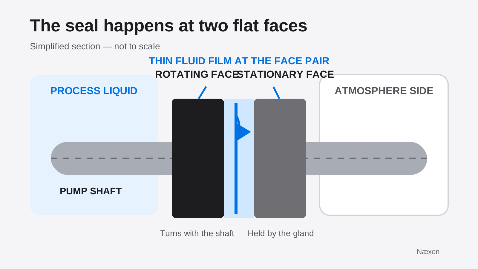
The drawing is a teaching schematic, not an installation drawing. Real seals can place the springs, rotating element, stationary element, sleeve, and secondary seals differently. A cartridge seal may arrive as a factory-set assembly, while another design may depend on a measured setting during installation. Never transfer dimensions or assembly steps from a generic diagram to a specific seal.
Why a good seal is not simply dry and tight
A common incorrect idea is that the two faces should be pressed together as tightly and as dry as possible. If the film becomes too thin or disappears in a seal designed for liquid lubrication, friction and heat rise rapidly. If the film becomes too thick, leakage can increase. Good operation is a balance created by the seal design, the pumped liquid or support fluid, face geometry, pressure, temperature, speed, and the condition of the equipment.
A very small amount of fluid can pass across the faces as part of normal operation and may evaporate before anyone sees a drop. That does not mean every visible leak is acceptable. The allowable condition is application-specific. A hazardous, hot, toxic, flammable, or environmentally controlled service can require a different seal arrangement and response than a clean-water training pump. The job documents and manufacturer define what is normal.
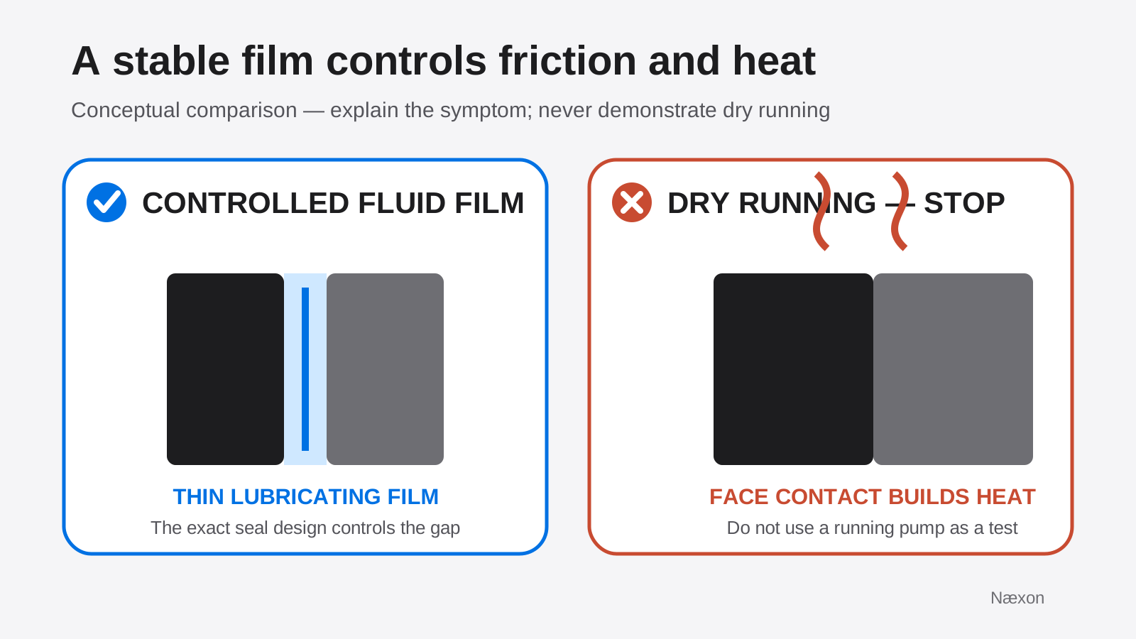
Some specialized seals are engineered for dry or gas operation, but that fact cannot be borrowed for a liquid-lubricated pump seal. The exact design controls. The safe field rule is simple: do not assume a mechanical seal can run without its required fluid merely because another seal type can.
Four leakage paths to keep separate
The face pair is only one possible path. Leakage may pass between the rotating and stationary faces, around a secondary seal on the shaft or sleeve, around a stationary seat in the gland, or at a gasketed joint between the gland and the pump. The location where liquid becomes visible does not always identify the path where it began.
This distinction matters during troubleshooting. Tightening gland fasteners may not correct leakage across damaged faces. Replacing the face pair may not correct a cut O-ring, a damaged sleeve, a contaminated gasket surface, or a connection leaking above the seal and running downward. Good diagnosis traces the liquid to its highest reliable origin while the equipment is in a safe condition.
Worked example: the leak appears after maintenance
Consider an illustrative pump returned to service after planned maintenance. The approved procedure was followed, the pump was filled and vented, and the seal support system was placed in service. During the controlled startup, an operator reports liquid collecting below the gland. This example does not set an acceptance limit; it shows how to organize evidence before replacing parts.
First, the crew stops at the boundary set by the operating procedure. They do not reach toward rotating equipment or place a hand near the coupling or gland. From the permitted observation point, they note when the liquid appeared, whether it is a mist, drip, or steady stream, and the highest visible wet location. They verify that the apparent leak is not coming from a vent, drain, flush fitting, instrument connection, or nearby flange.
Second, the team compares the condition with the exact seal arrangement and startup instructions. Was the pump properly filled and vented before rotation? Was the required flush, quench, buffer, or barrier service established in the right sequence? Were temporary setting devices removed or repositioned as required by that cartridge design? Was shaft rotation checked only by the approved method while isolated?
Third, the millwrights compare installation evidence. They confirm the seal identity, orientation, setting record, fastener sequence, gasket condition, sleeve condition, and any measured shaft movement allowed by the procedure. They also review alignment and soft-foot records because vibration or shaft movement can disturb the seal even when the visible symptom is leakage. The lesson on machine soft foot before shaft alignment explains one foundation condition that can keep returning.
The reasonableness check is the sequence itself. If the pump was dry before maintenance, leaked immediately on the controlled startup, and the leak can be traced to a disturbed joint, installation evidence deserves attention. If it ran normally and the condition appeared only after temperature, pressure, or vibration changed, operating conditions deserve equal attention. Neither pattern proves a cause by itself, but it prevents random part replacement.
A disciplined external check
- Protect the boundary. Follow the operating procedure, guarding requirements, and energy-control rules. Never inspect by touch near a rotating shaft, coupling, or hot leak.
- Identify the seal arrangement. Use the equipment tag, drawings, seal data, and maintenance record. Do not diagnose a single seal as though it were a dual pressurized system.
- Trace the highest wet point. Check permitted external connections, tubing, plugs, vents, drains, gland joints, and nearby piping before assigning the leak to the faces.
- Confirm required support conditions. Compare actual flush, cooling, buffer, barrier, pressure, temperature, and venting conditions with the approved documents. Record values and units; do not invent a universal limit.
- Review machine condition. Check available vibration, alignment, bearing, shaft-movement, and operating records. A seal may be the component leaking without being the original cause.
- Escalate with evidence. Give operations, reliability, or the seal specialist the observed sequence, leak location, equipment state, and measured conditions. Isolation and disassembly belong to the authorized procedure.
Symptoms and what they can mean
Leakage immediately at startup: possible causes include an incorrect setting, damaged secondary seal, contaminated or damaged face, wrong component, missing support fluid, incorrect venting, or a disturbed gasketed joint. Stop at the procedure-defined response and verify the installation record rather than tightening hardware blindly.
Leakage after the pump heats up: investigate temperature, pressure, support-system condition, alignment change, pipe strain, shaft movement, and the suitability of the selected seal for the service. The lesson on alignment changes after the first run provides the next machinery check.
Short life with worn or scored faces: contamination, loss of the lubricating film, unsuitable materials, vibration, excessive movement, or operating outside the design envelope may be involved. Face appearance is evidence for a qualified failure analysis, not permission to name one cause without the rest of the data.
Repeated seal replacement without improvement: look beyond the cartridge. Piping loads, base condition, soft foot, bearing condition, shaft runout, operation away from the pump’s intended range, seal-chamber conditions, and support-system reliability can all matter. A new seal installed into the same unresolved condition can repeat the same failure.
Common mistakes
The first mistake is calling every gland-area leak a failed face pair. Liquid can travel along surfaces and collect below its actual source. The second is treating a visible dry gland as proof that the seal is perfect. Some normal face leakage may evaporate, and some failures develop without an obvious puddle.
Another mistake is tightening fasteners around running equipment. Movement, hot liquid, pressure, and stored energy make casual adjustments unsafe, and tightening the wrong joint can distort parts or hide evidence. Use the approved shutdown and isolation process before service.
Finally, crews sometimes replace the seal while ignoring why it failed. The failed component deserves inspection, but so do alignment, support conditions, operating history, piping loads, and lubrication. The same system thinking applies to measured bearing lubrication: adding or replacing a component is not a substitute for controlling the condition around it.
Field Rules
- The primary seal is the rotating-and-stationary face pair; secondary seals close other paths.
- A liquid-lubricated seal needs the film specified by its design.
- Do not treat dry running as a test or assume a specialized dry-running seal proves another seal can do it.
- Trace leakage to its highest reliable source before choosing a repair.
- Never touch, tighten, or probe near rotating or pressurized equipment.
- Recurring seal trouble requires a system check, not just another cartridge.
Knowledge Check
- A pump leaks below the gland immediately after maintenance. What should be verified before concluding that the faces are damaged?
- Why can pressing the faces together harder create a problem rather than guarantee sealing?
- A seal begins leaking only after the pump reaches operating temperature. Which records should be compared?
- Why does replacing the same seal repeatedly fail to prove that the seal design is the root cause?
Answers and explanations
1. Verify the highest wet point, nearby connections and joints, seal identity, setting record, support-fluid sequence, venting, gasket condition, and safe startup observations. The visible collection point may not be the original path. 2. A liquid-lubricated design depends on a controlled fluid film. Too little film increases friction and heat; too much separation can increase leakage. The manufacturer’s design establishes the balance. 3. Compare temperature, pressure, support-system values, vibration, alignment, shaft movement, piping condition, and the approved operating sequence. Thermal change can reveal a system condition that was not obvious while cold. 4. The seal may be the part that leaks while another condition—such as pipe strain, vibration, shaft movement, contamination, or support-fluid loss—keeps damaging it. Repeating the replacement without controlling the system can repeat the result.
Practical Exercise
On paper, sketch a horizontal shaft passing through a pump casing. Add one rotating face, one stationary face, a thin fluid-film line, one shaft secondary seal, and one gland gasket. Draw four possible leakage arrows: across the faces, around the shaft secondary seal, around the stationary seat, and through the gland gasket. Then circle the checks that can be made externally without entering a guarded or energized area.
Your drawing is complete when the rotating and stationary parts are labeled, the process and atmosphere sides are clear, and each arrow begins at a different sealing path. Your checking method is to compare the sketch with Figure 1 and explain aloud why liquid seen below the gland does not prove which path failed. This is a paper exercise only; inspection, isolation, and service of real equipment remain governed by the site procedure and qualified supervision.