Evening Edition · Pipefitters and steamfitters · Apprentice to intermediate · Field Skill · 9-minute read
What you will learn: Trace an eight-bolt cross pattern, explain why opposite-bolt loading helps seat a gasket uniformly, evaluate flange-gap readings, and choose safe checks when a joint leaks.
The line has passed through bolt-up, but one side of the flange begins to weep during an authorized test. The quickest-looking response is to put a wrench on the wet-side nut. That response can make the joint less uniform, damage the gasket, or expose the crew to stored energy. A leak location is evidence, not permission to tighten a pressurized connection.
This lesson teaches the logic behind an eight-bolt cross pattern and a paper-based way to read the joint. It does not supply a universal torque. The approved joint-assembly procedure, flange and gasket design, fastener material, lubrication condition, engineering requirements, calibrated-tool requirements, and qualified supervision control the actual target and passes.
Before handling a flange, follow the site-specific energy-control and line-opening procedure. Isolate every applicable energy and material source, release or restrain stored energy, verify isolation, and confirm the authorized work scope. Never loosen or tighten a leaking, pressurized, hot, chemically hazardous, or otherwise energized joint as an improvised repair.
What the bolt pattern is trying to accomplish
A bolted flange joint seals when the assembly creates the required, sufficiently uniform gasket compression while keeping the flange, fasteners, and gasket within their permitted limits. The bolts do not seal the pipe by themselves. They supply clamp load; the flange faces distribute that load; the gasket conforms to the sealing surfaces and blocks the leak path.
Tightening one bolt changes the load around nearby bolts and can rotate or bend the flange locally. If a worker simply walks clockwise around a loose joint, the early bolts can pull one area closed while the opposite side remains open. Later bolts then fight a joint that is already cocked. A cross pattern alternates the load across the center so the faces approach each other more evenly.
That principle does not make every eight-bolt procedure identical. Some approved methods use multiple tools, different pass percentages, measured bolt elongation, hydraulic tensioning, or other controls. Use the sequence and target documented for the exact joint.
Read the eight-bolt sequence
Figure 1 numbers the pattern from the top position for training. Bolt 1 is opposite Bolt 2. Bolt 3 is opposite Bolt 4. The remaining diagonals pair 5 with 6 and 7 with 8. On the actual joint, a crew should establish and mark the approved starting position so everyone reads the same map; “top” on this page is only a drawing reference.
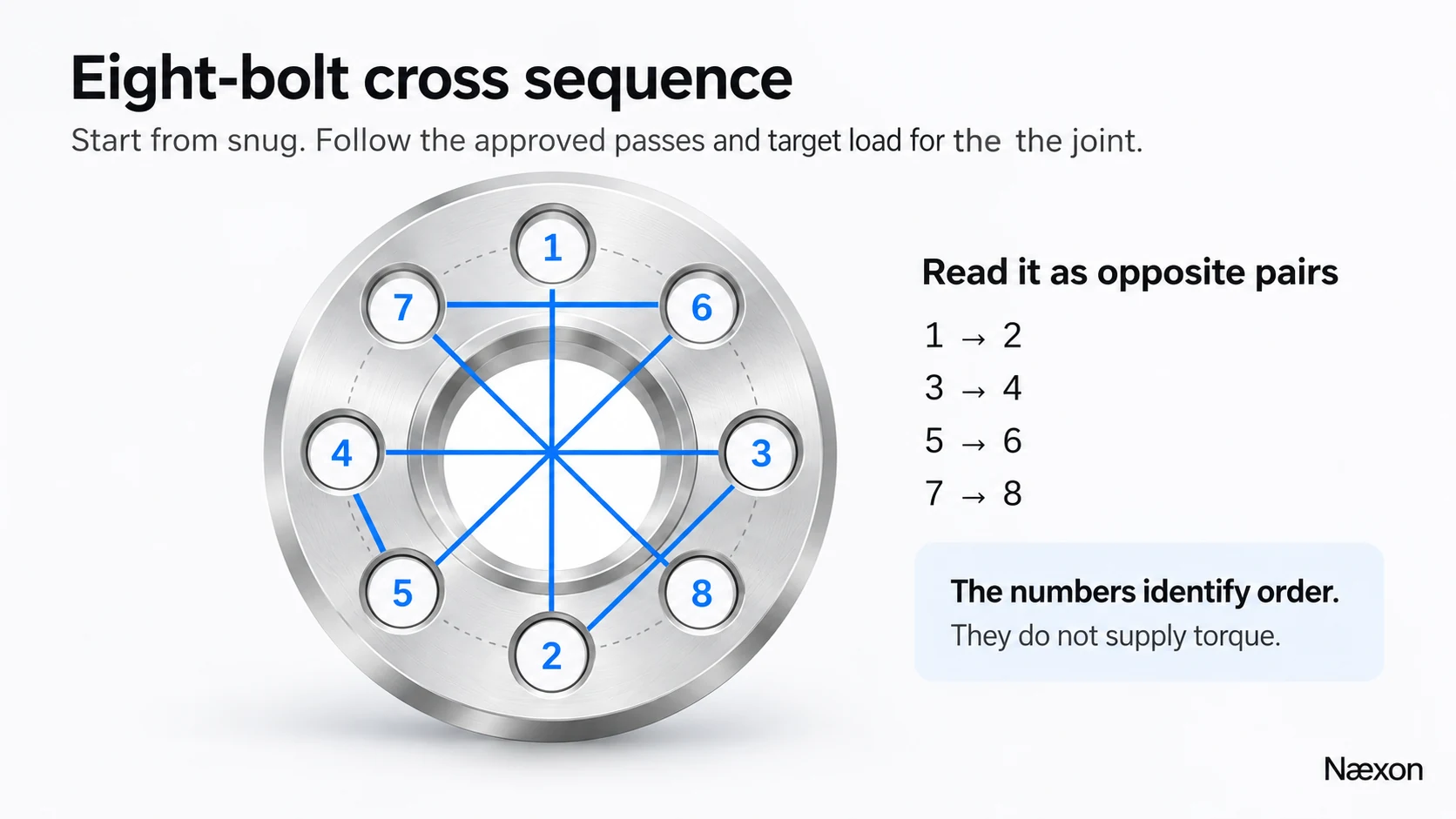
Begin from the snug condition defined by the controlling procedure, not from one fully tightened bolt. Complete the specified staged passes in the cross order. A final rotational pass may be required to find bolts that relaxed as neighboring fasteners were loaded. Do not invent the number of passes, target value, lubricant, or retightening rule from this diagram.
Worked example: use gap readings as evidence
Assume a training flange is isolated and safe, and its approved assembly plan permits gap measurements at four clock positions after a partial pass. The recorded illustrative gaps are 12 o’clock = 0.040 in, 3 o’clock = 0.042 in, 6 o’clock = 0.041 in, and 9 o’clock = 0.039 in. These values are not acceptance criteria.
Let g be the average measured gap. Carry the units through the calculation:
g = (0.040 in + 0.042 in + 0.041 in + 0.039 in) ÷ 4 = 0.162 in ÷ 4 = 0.0405 in
The largest reading is 0.042 in and the smallest is 0.039 in, so the observed spread is:
spread = 0.042 in − 0.039 in = 0.003 in
Check the average independently: 4 × 0.0405 in = 0.162 in, which returns the measured total. A reasonableness check also works: every reading lies near 0.040 in, so an average near 0.040 in is plausible.
The correct conclusion is not “the joint passes.” The readings show a relatively consistent training pattern at those four points. The approved procedure or engineering criteria decide whether the absolute gap, spread, measurement locations, and stage are acceptable. If one side instead measured much larger and the pattern was repeatable, the crew would stop and investigate alignment, gasket position, interference, flange condition, hardware, and the preceding tightening sequence rather than forcing the high side closed.
Uniform closure versus a cocked joint
Figure 2 reduces the joint to a side view. Parallel faces with an even gasket line are the intended geometric idea. A wedge-shaped gap is a warning that the faces are not closing uniformly. The cause may be piping strain, misalignment, a damaged or misplaced gasket, debris, face damage, uneven snugging, incorrect hardware, or an assembly step that did not follow the approved sequence.
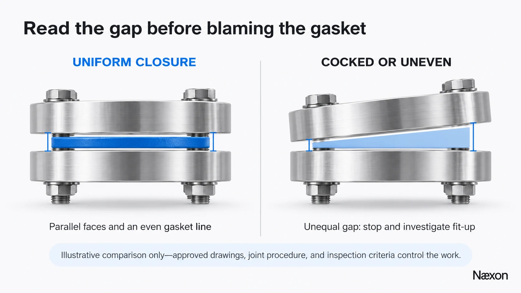
The common incorrect approach is to treat the nearest bolt as a jack screw and keep pulling until the gap looks closed. That can overload a fastener, rotate the flange, crush part of the gasket, or hide an alignment problem. The correct approach is to stop, preserve the observed pattern, and identify why the faces are not parallel under the authorized procedure.
A practical bolt-up method
- Establish the safe condition. Apply the required line-opening and energy-control procedure, isolate all sources, control residual pressure and temperature, and verify the isolation.
- Confirm the joint package. Match flange identity, facing, gasket, fasteners, washers, lubricant, and assembly instructions to the approved drawing, specification, and procedure. Review how to read flange markings when component identity is uncertain.
- Inspect before assembly. Check accessible sealing surfaces, gasket condition and centering, bolt and nut condition, flange alignment, and obstructions. Reject damage or contamination according to the controlling requirements.
- Bring the faces together without forcing fit-up. Support the piping and align the flanges within the approved method. Do not use the flange bolts to correct pipe strain or pull a misaligned system into place.
- Establish a uniform snug condition. Seat the nuts using the method defined by the procedure. Mark the starting bolt and sequence so the crew can reproduce and document each pass.
- Complete the cross passes. Follow 1 through 8 for every specified stage. Use the approved calibrated tool and target. Record the actual work instead of relying on memory.
- Complete required verification passes. Perform any specified rotational pass, gap check, bolt-load check, dwell, or retightening step. Retightening temperature-sensitive or in-service joints is never automatic; the governing procedure must authorize it.
- Inspect and release the joint. Confirm markings, records, visible condition, and required quality hold points before the system is returned for testing or service.
Troubleshooting a leak without chasing it
A joint leaks near one bolt during an authorized test: stop and follow the test and depressurization procedure. After the joint is isolated and verified safe, review the leak location, bolt-up record, gasket centering, flange-face condition, fastener condition, lubrication basis, tool calibration, and measured gap. The wet side may reveal the leak path, but it does not prove that one nut simply needs more torque.
One bolt continues to turn on the final check: confirm the procedure, tool, socket engagement, thread and nut condition, lubrication, washer seating, and whether neighboring bolts are redistributing load. Stop if the hardware shows galling, yielding, damaged threads, unexpected rotation, or loss of control. Do not exceed the approved target to make the mark line up.
The gap grows on the opposite side: check the sequence and fit-up. The joint may be rocking, pipe strain may be acting on the flange, or one side may have been advanced too far. Extra load is not a substitute for parallel alignment.
The leak returns after heat-up or cool-down: escalate to the responsible operations, engineering, and inspection personnel. Thermal movement, gasket relaxation, joint design, support movement, or service conditions may be involved. Do not assume a hot retorque is allowed.
The gasket appears extruded, torn, folded, or off-center: the joint requires an approved disassembly and inspection after full isolation. Do not attempt to push the gasket back into place or reuse it without explicit authorization.
Common mistakes
Frequent errors include numbering the joint differently among crew members, skipping the snug stage, completing one bolt to final target before the others, changing lubricant without recalculating or reauthorizing the procedure, using unverified torque values, using flange bolts to pull piping into alignment, and failing to record the final pass.
Another mistake is assuming that a torque wrench directly measures gasket compression. Applied torque is influenced by thread and bearing friction as well as fastener geometry and condition. That is why material, lubrication, tool calibration, and the approved engineering basis matter. A precise wrench reading cannot rescue an incorrect joint package or damaged hardware.
Field Rules
- Never improvise work on an energized or pressurized flange.
- Start from a uniform snug condition defined by the procedure.
- Cross the center; do not walk one direction around a loose joint.
- The sequence controls order, not the target torque.
- Use flange bolts to clamp an aligned joint, not to correct pipe strain.
- Record each pass and investigate repeatable unevenness.
- A leak location is a clue, not a diagnosis.
Knowledge Check
- On Figure 1, which bolt follows Bolt 3, and why?
- A crew reaches the approved target on Bolt 1 before snugging the remaining bolts. What is wrong with that approach?
- Four training gap readings are 0.036, 0.041, 0.039, and 0.044 in. What is the spread?
- A test joint weeps near Bolt 8. What is the first principle that controls the response?
- Why can two identical torque readings create different bolt loads if the friction conditions differ?
Answers
- Bolt 4. It is opposite Bolt 3, so the sequence moves the load across the flange instead of advancing around one side.
- It can create uneven early compression. The approved method starts from a defined snug condition and builds the load through staged cross passes.
- 0.008 in. Subtract the smallest reading from the largest: 0.044 in − 0.036 in = 0.008 in. Only the controlling criteria can say whether that spread is acceptable.
- Stop and follow the test, isolation, and depressurization procedure. Do not tighten the wet-side bolt on an energized joint.
- Much of the input torque is spent overcoming friction. Different thread, bearing, lubricant, coating, or surface conditions can change the relationship between torque and bolt load.
Practical Exercise
Print or sketch an eight-hole circle. Put Bolt 1 at the top, then number the pattern 1 top, 2 bottom, 3 right, 4 left, 5 lower-left, 6 upper-right, 7 upper-left, and 8 lower-right. Draw one continuous line through the order. Your result should cross the center repeatedly and show the opposite pairs 1–2, 3–4, 5–6, and 7–8.
Next, write the four worked-example gaps around the sketch and independently calculate the average and spread. The expected results are 0.0405 in average and 0.003 in spread. State beneath the math: “Training evidence only; the approved joint procedure supplies acceptance criteria.” Keep this exercise paper-based or use a fully isolated training rig under qualified supervision.
Related learning
Use Class 150 versus Class 300 flange ratings as a prerequisite for separating pressure-temperature class from assembly torque. Continue with two-holing a flange without dedicated pins for orientation work, then study why flanges sometimes refuse to align before using fasteners to overcome a fit-up problem.