Pipefitting and steamfitting • Fundamentals • Apprentice to journeyman • 8-minute read
Learn to separate a flange’s class from its actual pressure rating, follow a pressure-temperature lookup, and recognize when a component needs engineering review.
The number on the flange starts the check
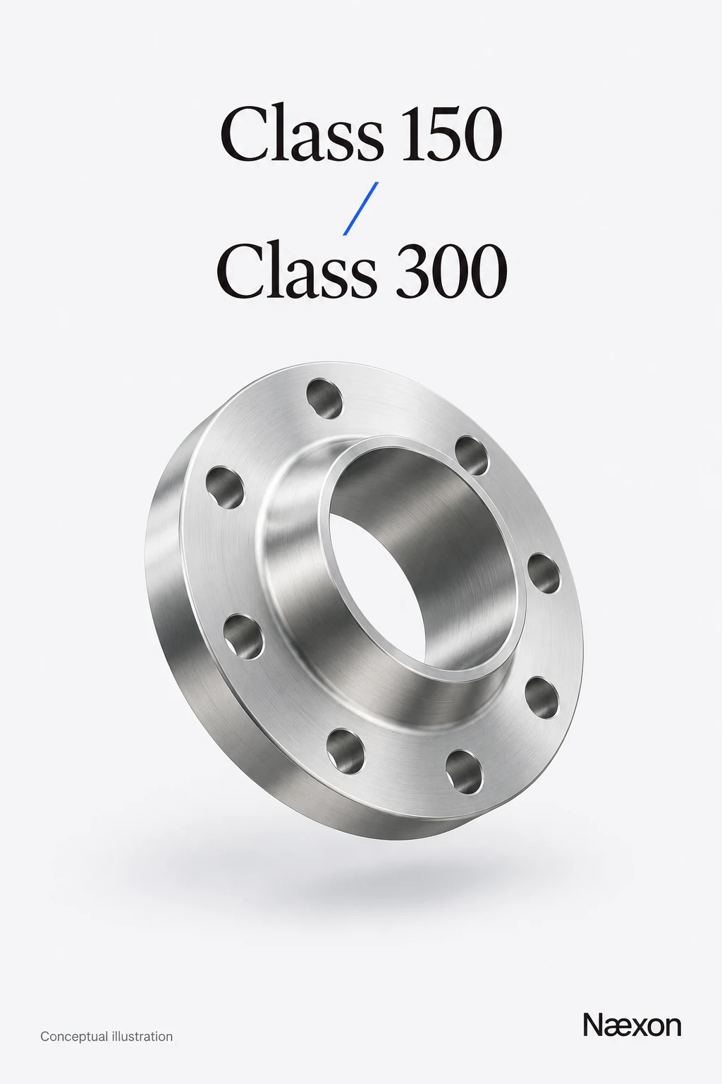
Somebody calls for a four-inch flange, and the rack has two that look close enough until you put them beside each other. One is Class 150. The other is Class 300. Grabbing the heavier one because it “must be better” can still send the wrong component to the job.
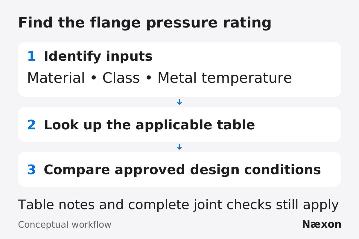
Class identifies a standardized rating category. It does not give you a standalone working pressure in pounds per square inch. To evaluate a flange, you need its material, the governing standard and edition, the applicable temperature, and the approved piping requirements. Physical fit is another check, not a substitute for those details.
This lesson builds on the flange size and bolt-hole reference. That reference helps identify dimensions; here, the focus is interpreting the rating and knowing what the comparison proves.
What Class 150 and Class 300 identify
ASME B16.5 covers both classes in nominal pipe sizes NPS ½ through NPS 24. It addresses pressure-temperature ratings along with materials, dimensions, tolerances, marking, testing, and related joint requirements. Its Class 2500 flange range is smaller, ending at NPS 12, so even the standard’s size range needs to be read with the class.
For larger steel flanges, ASME B16.47 covers NPS 26 through NPS 60 within its specified classes. Check the required series and actual dimensional standard rather than extending a B16.5 chart beyond its range. A large-diameter flange needs the same careful identification as a small one.
On a material ticket, “150-pound” or “300-pound” may be familiar shorthand. Write and read these as Class 150 and Class 300. Neither label tells you the component’s weight, and neither means a universal 150-psi or 300-psi operating limit.
Material and temperature complete the rating
A pressure-temperature table is organized around a defined material group. Establish the exact material specification and grade before choosing that table. “Carbon steel” or “stainless” alone leaves too much unresolved. Use the flange-markings lesson if you need a refresher on separating the material, class, size, and traceability information.
The temperature used for rating must come from the applicable design basis. It is the relevant pressure-containing metal temperature, not simply today’s air temperature or a convenient normal operating reading. Follow the governing code and approved documents for how that temperature is established and which pressure-temperature conditions must be evaluated.
A room-temperature rating cannot automatically be carried into hot service. Published ratings commonly decrease as temperature rises, and material notes can impose additional restrictions. Conversely, a table’s low-temperature row is not permission to assume that every listed material is suitable for any cold service.
Read the table heading, units, material notes, and temperature row together. A correctly copied pressure from the wrong material group is still the wrong answer.
A worked comparison that changes with temperature
Consider a paper exercise using ASTM A105 flanges in ASME B16.5 Material Group 1.1. Published manufacturer data gives Class 150 a rating of 285 psig (pounds per square inch gauge) at 100°F and 170 psig at 500°F. Class 300 is listed at 740 psig and 605 psig at those same temperatures. These are selected educational values, not a replacement for the governing table and its notes.
Assume the exercise requires checking 250 psig at a metal temperature of 500°F. Use that temperature row, not the 100°F row. For a simple numerical comparison, define the difference as the tabulated rating minus the stated pressure requirement, with both expressed in psig.
For Class 150, the difference is 170 − 250 = −80 psi. The required pressure exceeds that tabulated rating by 80 psi. For Class 300, it is 605 − 250 = 355 psi. Class 300 clears this pressure-temperature comparison by 355 psi.
Neither difference is a calculated safety factor or permission to operate. The exercise checks one rating requirement only. Materials, service restrictions, mating equipment, loads, gasket, bolting, and the approved piping specification still govern the connection.
As a reasonableness check, using the wrong 100°F row would make Class 150 appear to clear the same pressure by 285 − 250 = 35 psi. That reversal shows why temperature belongs beside every quoted pressure rating.
Notice also that 740 ÷ 285 is approximately 2.60. For these particular conditions, Class 300’s listed rating is not twice Class 150’s. Do not multiply a class number or scale a remembered rating to invent another one.
Why the dimensions still matter
A Class 300 component is not automatically a drop-in upgrade for a Class 150 connection. Outside diameter, thickness, bolt circle, holes, and bolting can differ for the same nominal pipe size. Check the actual type, size, class, facing, and dimensional standard against the approved connection.
Counting holes alone will not establish compatibility. Two flanges can have the same hole count while the bolt circle and hole diameter differ. The bolt-circle and hole-spacing lesson explains the geometry, but calculated spacing does not prove material identity or pressure suitability.
Keep bore and pipe wall requirements in the comparison too. A weld-neck flange’s connection end must match the specified joint preparation. Never enlarge holes, alter the face, or force the connection to make an unapproved substitution fit.
The gasket and bolts belong to the same decision
The flange body is one part of a bolted joint. Correct facing, gasket selection, bolting materials, lubrication, assembly loads, alignment, and inspection all matter. Class alone supplies no universal torque value.
Use the approved assembly procedure for the exact connection. ASME PCC-1 provides bolted-joint assembly guidance within its scope, but citing the standard does not replace a suitable project procedure or the required training. A generic internet torque chart cannot resolve an unidentified gasket or unknown fastener material.
If a connection leaks, do not diagnose the problem by deciding that it needs “more torque” or a higher-class flange. Follow the site response, isolation, and qualified inspection process. This lesson does not authorize work on pressurized, hot, or otherwise hazardous equipment.
A practical verification sequence
Start with the current drawing, line specification, and material requirements. Record the required NPS, flange type, class, material, facing, bore, and governing standard. Then compare the physical markings and traceability records. Missing or conflicting identification belongs with material control or QA before installation.
Next, use the approved pressure-temperature design basis to locate the appropriate table and notes. Record the material group, temperature, class, rating, units, and document revision. If a value falls between rows, use only the treatment permitted by the governing documents; do not quietly choose the cooler row.
Finally, verify the mating component, gasket, bolting, dimensions, and approved assembly procedure. Record the conclusion as a completed check or a specific hold. “Looks right” is not a traceable result.
Common mistakes worth catching early
The first mistake is treating the stamped number as psi. The next is remembering a valid rating but forgetting the material or temperature that made it valid. Both disappear when the recorded result includes the whole lookup.
Another mistake is assuming that a higher class can replace a specified lower class without review. A rating comparison does not revise the drawing, guarantee fit, or approve a material change. Similarly, a successful dimensional check does not restore a missing heat number or establish an unknown grade.
When paperwork and the component disagree, stop that selection and identify the mismatch. Do not choose whichever source makes the part easiest to install.
Field Rules
- Record class, material, temperature, and pressure units together.
- Check the governing standard’s size, class, and series limits.
- Keep dimensional fit and service suitability as separate checks.
- Use the specified gasket, bolting, and approved assembly procedure.
- Escalate missing identity or conflicting requirements before installation.
Knowledge Check
- A flange is stamped Class 150. What information is still needed before quoting its pressure rating?
- In the worked example, can Class 150 satisfy the 250-psig requirement at 500°F?
- Two flanges have eight bolt holes each. Does that prove they can be connected?
- Class 300 clears the example’s rating comparison. Can the fitter substitute it for the specified flange?
- A drawing calls for NPS 30. Should you extend the last row of a B16.5 chart?
Answers and explanations
- Establish the exact material and applicable material group, governing standard and edition, relevant metal temperature, and table notes. Then compare the rating with the approved service requirements.
- No. Its stated rating is 170 psig, which is 80 psi below the requirement. The cooler-temperature rating is not applicable to this comparison.
- No. Bolt circle, hole size, facing, dimensions, materials, and the engineered connection still need verification.
- No. The arithmetic completes one check. Any substitution needs the approval required by the project; pressure capability alone does not establish compatibility.
- No. Identify the applicable large-diameter standard and series. B16.47 covers that nominal size within its scope; confirm the actual project requirement rather than extrapolating.
Practical Exercise
On paper, repeat the A105 comparison for a hypothetical requirement of 180 psig at 500°F. Write the material group, temperature, pressure units, and two ratings before doing the subtraction. Then state what remains unresolved.
Your numerical results should be −10 psi for Class 150 and +425 psi for Class 300. The first falls short; the second clears only the tabulated pressure comparison. Your remaining checks should include the approved specification, mating component, dimensions, gasket, bolting, service limits, and assembly requirements. No live equipment work is part of this exercise.