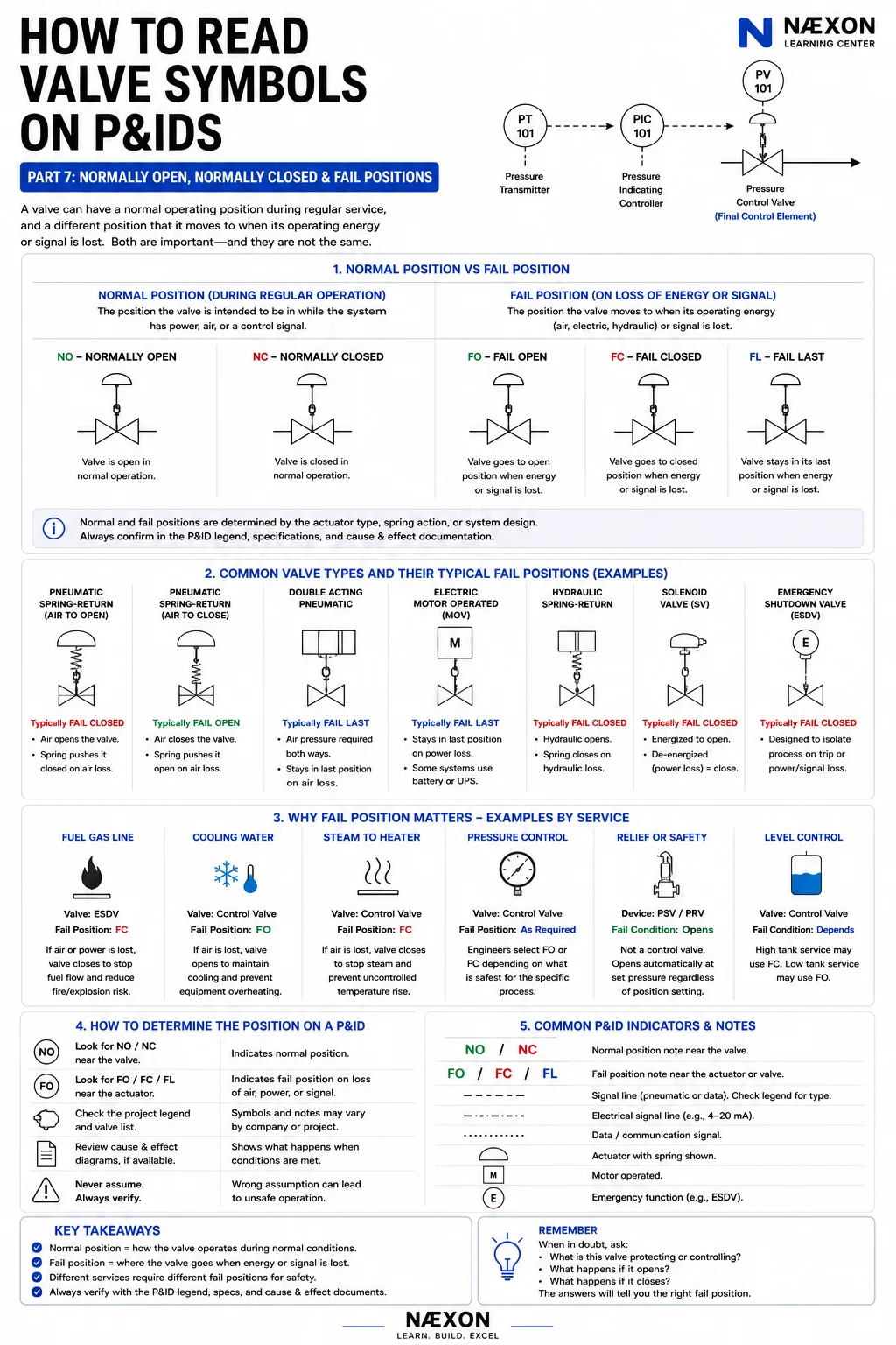
Morning Edition · Electricians · Apprentice · Fundamentals · 10-minute read
What you will learn: Identify normally open and normally closed contacts from their reference state, predict how each contact changes when its device operates, and trace a simple control rung without confusing the contact name with the machine command.
The control drawing shows a Stop pushbutton as normally closed and a Start pushbutton as normally open. At first glance, that can sound backward. If Stop means stop, why is its contact drawn closed? If Start means run, why is its contact drawn open? The answer is that normally open and normally closed describe the contact in a defined reference condition. They do not describe what the machine is supposed to be doing.
This distinction is the starting point for reading relay logic, motor-starter schematics, limit-switch circuits, permissives, alarms, and many PLC input drawings. Once the reference state is clear, the circuit stops looking like a collection of labels and starts behaving like a sequence you can predict.
This lesson is a drawing-reading exercise, not authorization to work energized or design a machine-safety circuit. The approved drawings, equipment documentation, risk assessment, electrical safety program, and qualified supervision control real work. A pushbutton, selector switch, or control relay is not an energy-isolating device.
“Normal” is a reference condition
For a momentary pushbutton, normal usually means the operator is not pressing it. For a relay or contactor auxiliary contact, normal means the coil is de-energized. For a mechanically operated limit switch, normal refers to the specified unoperated actuator condition unless the drawing or device documentation establishes a different reference. The physical machine may hold a field-mounted limit switch operated during ordinary production, so never substitute “the plant is running normally” for the device’s defined reference state.
A normally open, or NO, contact has no conducting path through that contact in the reference condition. Operating the device closes the contact. A normally closed, or NC, contact has a conducting path in the reference condition. Operating the device opens it. When the device returns to its reference condition, a maintained or spring-return mechanism returns the contact as designed.
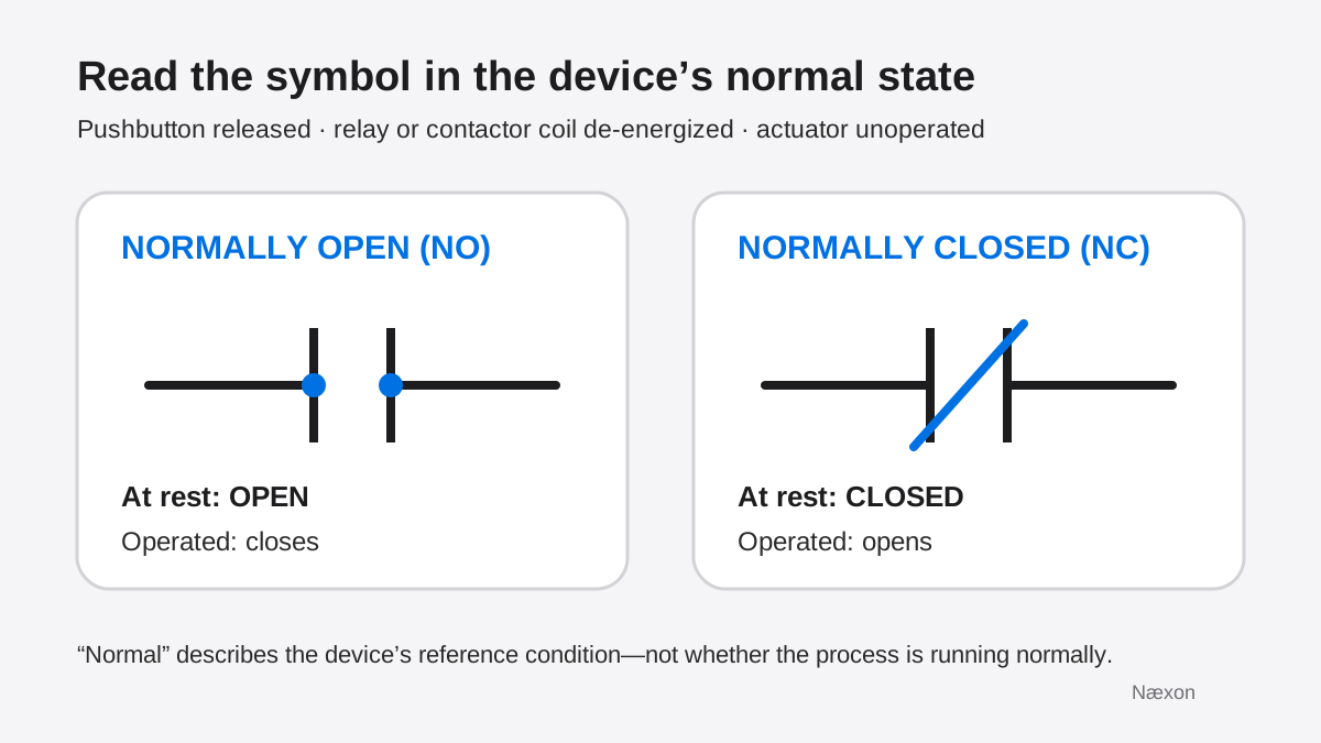
The symbol is a functional statement, not a photograph of the hardware at every moment. A ladder diagram commonly keeps the same NO or NC symbol while the electrician mentally changes its conducting state as the associated pushbutton, relay coil, pressure switch, limit switch, or other device changes condition.
Contact name and machine purpose are different
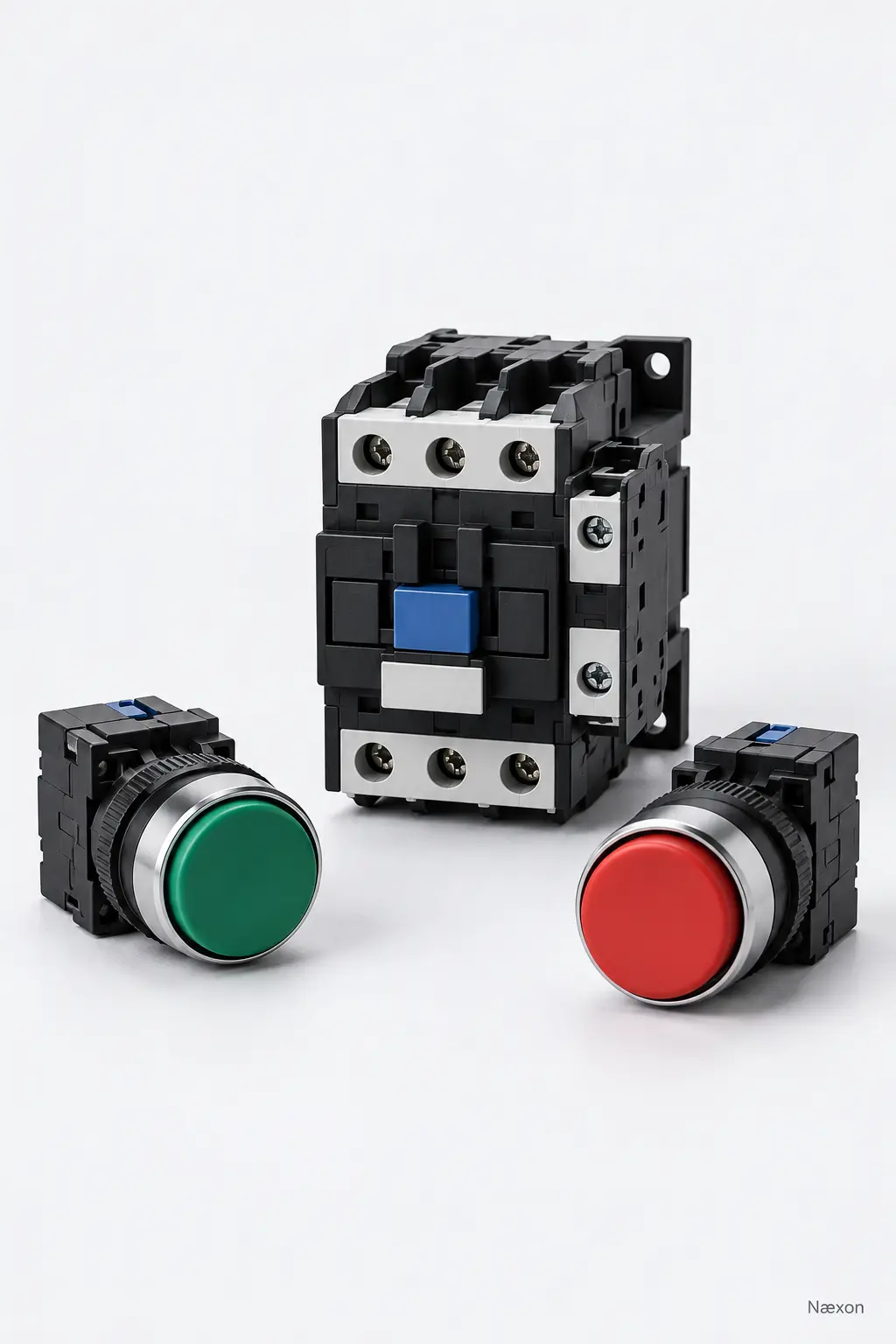
The word on the operator device tells you its intended command. The contact designation tells you what its internal electrical path does in the reference state. A green Start pushbutton can use a normally open contact because pressing it closes the path that initiates a command. A red Stop pushbutton in a conventional control rung often uses a normally closed contact because pressing it opens the control path. The label and the contact type answer different questions.
Do not turn that familiar arrangement into a universal design rule. Emergency-stop functions, guard circuits, safety relays, redundant channels, monitored contacts, and process shutdown systems require equipment-specific design and validation. This lesson explains basic contact action only; it does not specify a safety architecture.
Worked example: trace a simple Start–Stop rung
Consider the simplified training rung in Figure 2. From left to right it contains a normally closed Stop contact, a normally open Start contact, and control-relay coil CR. There is no holding contact in this example because the purpose is to isolate the state change of the two pushbuttons.
Assume both buttons are released. The Stop device is in its reference condition, so its NC contact conducts. The Start device is also in its reference condition, so its NO contact blocks the path. Because the series path is open at Start, coil CR is de-energized.
Now press and hold Start while Stop remains released. Operating Start closes its NO contact. The Stop NC contact still conducts, so the series path is complete and coil CR energizes. Release Start and its contact returns open; the path breaks and CR de-energizes. Pressing Stop at any point opens the NC Stop contact and also breaks the path.
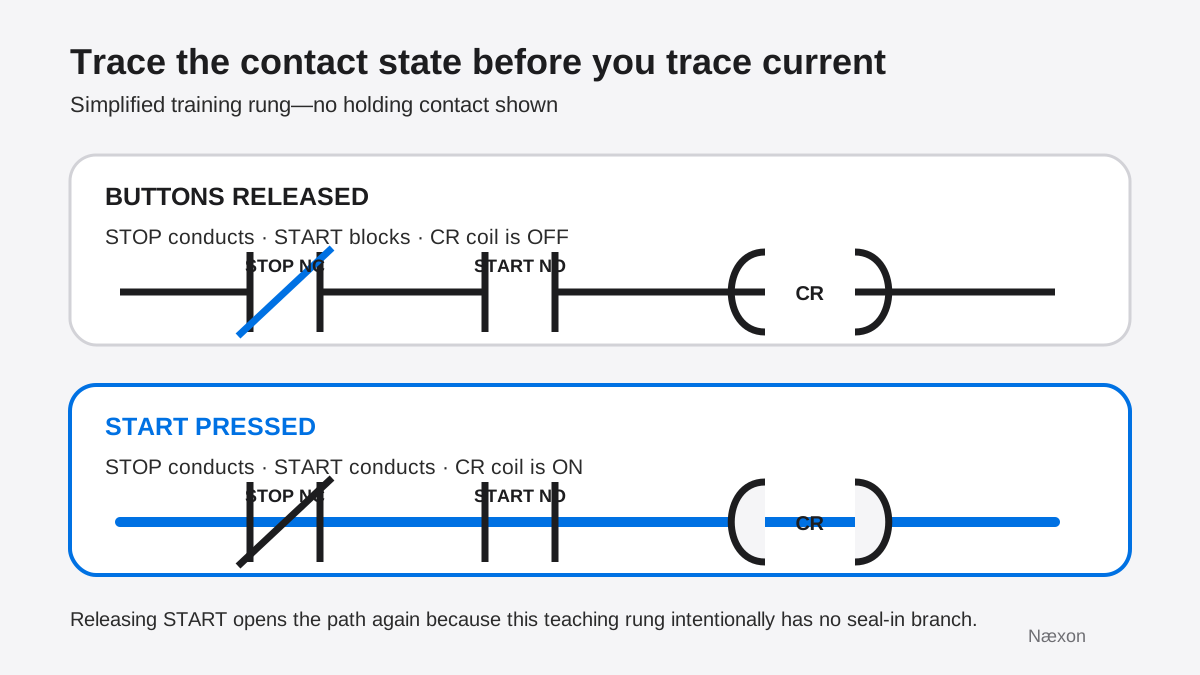
A quick independent check is to ask what must happen when the operator removes a finger from Start. In this intentionally simplified rung, the Start contact returns open, so CR must turn off. If the drawing is supposed to keep CR energized after Start is released, another path is missing from this training rung. A common three-wire starter adds a normally open CR or M auxiliary contact in parallel with Start to create a holding path. The related contactor lesson shows that deeper application.
The common wrong approach
The incorrect approach is to read the device label first and force the symbol to match the command: “Stop means open” or “Start means closed.” That reverses the reference logic and causes errors as soon as a relay auxiliary, pressure switch, or limit switch appears. You can recognize the mistake when someone describes a contact only by what they want the machine to do and never states whether the device is actuated or its coil is energized.
The correct approach names three things in order: the device’s reference condition, the contact type, and the operated change. For example: “With relay coil CR de-energized, CR’s NO auxiliary contact is open. When CR energizes, that auxiliary contact closes.” That sentence can be checked against the schematic and the device data without guessing what “normal operation” means.
A practical method for reading contacts
- Find the device tag. Match the contact label to its pushbutton, relay coil, contactor, switch, or sensor. Contacts carrying the same relay tag are operated by that relay even when they appear on different rungs.
- Define the reference state. State whether the button is released, the coil is de-energized, or the mechanical actuator is unoperated. Use the drawing legend and device documentation where the reference is not obvious.
- Identify NO or NC. Read the symbol and any terminal or contact designation provided by the manufacturer. Do not infer contact type from wire color, device color, or the command name.
- Mark the present device condition. Decide whether the device is currently in its reference state or operated state. Field position can differ from the symbol’s reference condition.
- Change only the affected contacts. If a relay coil energizes, update every contact carrying that relay tag. NO contacts close and NC contacts open, subject to any documented timing or special contact function.
- Trace the complete path. Follow the approved schematic from source through each series and parallel branch to the load and return. One open series contact is enough to interrupt that path.
- Check the result against circuit purpose. Confirm that the predicted coil, lamp, valve, or input state makes sense. If it does not, recheck the reference condition, tag matching, and branch connections before blaming hardware.
Safety boundary: open contacts do not prove zero energy
An open control contact can stop a command while hazardous energy remains available elsewhere. A Stop button may de-energize a contactor coil, yet line-side conductors can remain energized and stored mechanical, pneumatic, hydraulic, or thermal energy can remain. Control-circuit devices do not replace the approved energy-isolation procedure.
Before exposure to conductors or servicing of equipment, qualified personnel must follow the applicable electrical safe-work and hazardous-energy-control procedures. Isolation, lockout or tagout where required, release or restraint of stored energy, and verification of the de-energized condition must be performed under the site program. Never use the position of a pushbutton, a pilot light, a PLC display, or an inferred contact state as proof that equipment is safe to touch.
Troubleshooting contact-state mistakes
If the drawing predicts a coil should be off but it remains on, first confirm that the correct drawing revision and device tag are being used. Look for a parallel holding path, a remote command, a maintained selector, or another contact bypassing the branch you traced. Do not assume the contact symbol changed meaning.
If a field input seems reversed, verify whether the input is wired through a physical NO or NC contact and whether the PLC logic examines the input as true or false. Physical contact state, input-module indication, and program instruction are three different layers. Record each layer separately rather than calling all of them “normally closed.”
If continuity does not match the expected de-energized contact state, stop and establish the approved safe condition before testing. Isolate the contact from parallel paths as the procedure requires, verify the correct terminals, and compare the result with the exact device documentation. A welded contact, broken actuator, incorrect contact block, wiring error, or parallel circuit can all mislead an in-circuit resistance check.
Escalate when the drawing and installed device do not agree, the contact function is part of a safety system, energized testing would be required without an approved justification, or the equipment has unexplained movement, damaged insulation, overheating, arcing, or repeated protective operation.
Common mistakes
Frequent errors include treating “normal” as the plant’s usual operating condition, assuming a red button must contain an open contact, tracing only the device label instead of the tag, forgetting that one relay coil can operate several contacts, reading the symbol as the contact’s present field position, overlooking a parallel branch, and confusing physical contacts with PLC instructions.
Another serious mistake is using an open control contact as isolation. A control path can interrupt a command without physically isolating the hazardous energy source. Drawings help you understand function; the energy-control procedure establishes the safe work condition.
Field Rules
- Define the device’s reference condition before naming the contact state.
- NO is open at reference and closes when operated; NC is closed at reference and opens when operated.
- The device label describes purpose; the contact designation describes electrical action.
- Update every contact carrying an energized relay or contactor tag.
- Trace every series and parallel path before deciding what the load should do.
- Never treat a control device or an open contact as energy isolation.
Knowledge Check
- A relay coil is de-energized. What state should its ordinary NO auxiliary contact be in?
- A momentary Stop pushbutton uses an NC contact. What happens to that contact when the button is pressed?
- In Figure 2, both buttons are released. Which device blocks the current path to CR?
- Relay CR energizes and operates one NO and one NC auxiliary contact. How does each change?
- The Stop button is pressed and the motor stops. Does that prove the starter enclosure is safe to open?
Answers
- The NO auxiliary is open because the relay coil is in its de-energized reference condition.
- The NC Stop contact opens when the button is operated, interrupting the control path.
- The released Start pushbutton blocks the path because its NO contact is open. The released Stop contact conducts.
- The CR NO contact closes and the CR NC contact opens. Both changes are caused by the same energized coil.
- No. The Stop button is a control device, not an energy-isolating device. Follow the approved isolation, lockout/tagout, stored-energy, and verification procedures.
Practical Exercise
On paper, draw four rows labeled Start pushbutton, Stop pushbutton, relay CR NO auxiliary, and relay CR NC auxiliary. Add columns for reference condition, contact state at reference, operated condition, and contact state when operated. Then add a fifth row for the simplified Figure 2 rung and write the CR coil state for buttons released, Start pressed, and Stop pressed.
Your completed check should show: released Start—open; pressed Start—closed; released Stop—closed; pressed Stop—open; CR coil de-energized—CR NO open and CR NC closed; CR coil energized—CR NO closed and CR NC open. For Figure 2, CR is off with both buttons released, on while Start is held and Stop remains released, and off when Stop is pressed. Keep this as a drawing exercise or use only a supervised, de-energized training board designed for instruction.
Related learning
Build the broader drawing foundation with How to Read an Electrical One-Line Diagram. Then apply NO and NC contact tracing to a motor-contactor holding circuit and chatter diagnosis. For a different motor fault path, continue with what electricians check when a motor trips on startup. Before any absence-of-voltage verification task, review the live–dead–live meter-checking sequence.