Morning Edition · Electricians · Apprentice · Fundamentals · 10-minute read
What you will learn: Read the voltage and VA fields on a control-transformer nameplate, calculate rated secondary current, total steady and pickup loads without mixing them, and recognize when manufacturer selection data must decide the application.
A motor-control panel contains a small transformer marked 100 VA with a 120 V secondary. How much current can that secondary supply? The arithmetic is short, but the field decision is not. A contactor coil may demand much more apparent power while pulling in than after its armature seals, so a transformer that appears lightly loaded during normal operation can still allow the control voltage to sag at startup.
This lesson explains the nameplate relationship and a disciplined load check. It does not select a transformer, overcurrent device, conductor, tap, or grounding arrangement for a real installation. Approved drawings, the exact transformer and load documentation, applicable electrical rules, and qualified supervision control those decisions.
What VA means on a control transformer
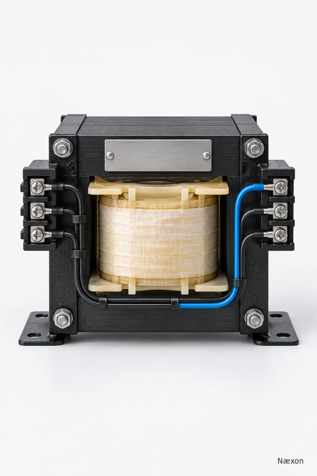
A control transformer changes an AC supply voltage to the voltage required by a control circuit. A common application is stepping a higher motor-circuit voltage down to a lower control voltage for coils, relays, pilot lights, and other devices. The actual primary and secondary connections must follow the nameplate wiring diagram and approved schematic; terminal positions and jumper arrangements are not universal.
The transformer rating is normally expressed in volt-amperes, or VA. VA is apparent power in an AC circuit. For the single-phase nameplate relationship used here:
VA = V × I
where V is volts and I is amperes. Rearranging the same relationship gives:
I = VA ÷ V
The voltage used in the division must match the winding whose current is being calculated. Dividing by the secondary voltage gives secondary current. Dividing by the primary voltage gives primary current for an ideal rating calculation; actual design, losses, protection, and code application require the manufacturer's data and project requirements.
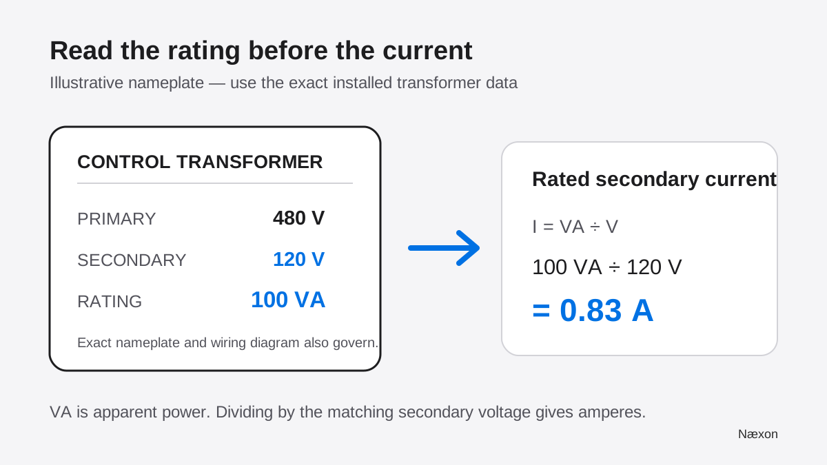
Figure 1 also shows why saying that a transformer is “100 watts” is imprecise. Control-transformer and connected-device data are commonly stated in VA because current and voltage can be out of phase in inductive loads. Do not replace a documented VA value with watts or assume that the two are interchangeable.
Rated current is not the same as actual load current
The current calculated from the nameplate is a rating relationship, not a prediction that the circuit always draws that current. Actual current depends on which devices are energized and their operating condition. A pilot light may have one stated VA load. An electromagnetic contactor or relay can have separate inrush VA and sealed VA.
Inrush VA describes the higher demand while an electromagnetic device is pulling in. Sealed VA describes the lower demand after the magnetic assembly has closed and is being held. The transformer must support the loads that are on continuously and the devices that pick up at the same time. A series of devices that start separately can present a different worst case from several coils commanded together.
This is why a simple sum of sealed VA does not complete a control-transformer selection. Manufacturer selection procedures commonly begin with total sealed VA, then account for simultaneous coil inrush and the voltage regulation required during pickup. The transformer's published inrush capability or selection table—not an improvised percentage—governs the decision.
Worked example: current and two load conditions
Assume an illustrative control transformer has a 100 VA, 120 V secondary. Let ST be transformer VA, VS secondary voltage, and IS rated secondary current.
IS = ST ÷ VS = 100 VA ÷ 120 V = 0.833 A
Rounded to two decimal places, the rating relationship is 0.83 A. The units check: volt-amperes divided by volts leaves amperes.
Now assume the manufacturer's data for the connected devices lists one contactor coil at 58 VA inrush and 8 VA sealed, two energized relays at 4 VA each, and one pilot light at 3 VA. These values are deliberately illustrative; real values must come from the exact device documentation.
During contactor pickup, use the contactor's inrush value while adding the other loads that are already energized:
Spickup = 58 VA + (2 × 4 VA) + 3 VA = 69 VA
The corresponding illustrative secondary current is:
Ipickup = 69 VA ÷ 120 V = 0.575 A ≈ 0.58 A
After the contactor seals, replace its inrush value with its sealed value:
Ssealed = 8 VA + (2 × 4 VA) + 3 VA = 19 VA
Isealed = 19 VA ÷ 120 V = 0.158 A ≈ 0.16 A
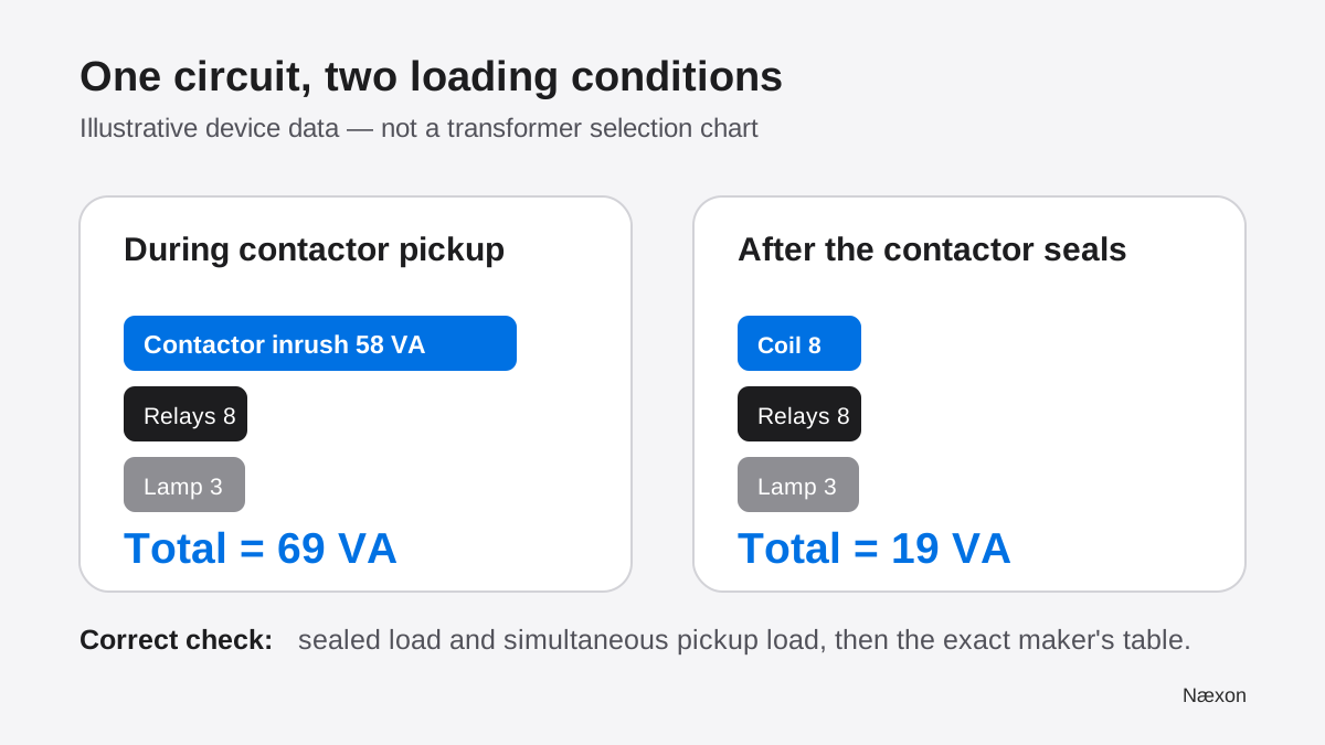
A reasonableness check supports the arithmetic. Sixty-nine VA is less than the 100 VA continuous nameplate number, so its calculated current must be less than 0.83 A; 0.58 A is. Nineteen VA is about one-fifth of 100 VA, so 0.16 A should be about one-fifth of 0.83 A; it is.
That comparison still does not approve the 100 VA transformer. The exact maker's inrush or regulation table must show that the chosen unit maintains the required secondary voltage for the simultaneous pickup load. Frequency, primary voltage, taps, ambient conditions, duty, protective-device coordination, conductor voltage drop, and the load devices' allowable voltage ranges may also matter.
The correct field method
- Start with the approved drawing. Identify the transformer tag, primary source, secondary voltage, grounding arrangement, protective devices, and every load the secondary serves.
- Read the complete nameplate. Record VA, frequency, primary and secondary voltages, available taps, terminal diagram, and any manufacturer markings or limitations. Do not infer connections from physical position alone.
- List every connected load. Use exact device data. Separate ordinary VA, coil inrush VA, and coil sealed VA. Note which devices can be energized together.
- Calculate the winding current relationship. Use I = VA ÷ V with the voltage for that winding and keep the units visible.
- Build operating cases. Total the steady load and each credible simultaneous pickup case. Do not add one coil's inrush and sealed values at the same instant.
- Use the manufacturer's selection method. Compare sealed VA and simultaneous inrush with the exact transformer's published tables or procedure. Apply the approved voltage-regulation requirement rather than inventing a margin.
- Check the installation requirements. Confirm connections, taps, overcurrent protection, conductor sizing, grounding, enclosure, temperature, and terminal torque from governing documents.
- Verify safely. Inspection or testing around exposed parts follows the employer's electrical safe-work program. Deenergize, isolate, lock out, and have a qualified person verify the condition unless an energized task is specifically justified and controlled.
Incorrect approach versus correct approach
The common incorrect approach totals only the sealed VA printed for coils and declares the transformer large enough. That method can miss the moment when one or more magnetic devices pull in. A symptom may appear as a contactor that hesitates, drops out, or chatters even though the steady-state load seems small.
The correct approach keeps two questions separate. First, does the transformer's continuous VA relationship support the connected steady load? Second, does its published inrush performance maintain suitable secondary voltage during the worst credible simultaneous pickup? Both answers need the exact load data and manufacturer selection information.
Another error is dividing transformer VA by the primary voltage and calling the result “available secondary current.” For a 100 VA transformer, 100 VA ÷ 480 V describes about 0.21 A on the illustrative primary side, while 100 VA ÷ 120 V describes about 0.83 A on the secondary side. The VA relationship is shared, but the current changes with the winding voltage.
Troubleshooting a weak control circuit
Secondary voltage looks normal with no command but collapses during pickup: compare the simultaneous inrush load with the exact transformer selection data. Also inspect the primary supply under load, tap selection, protection and holders, conductor and terminal condition, secondary wiring, and control-path voltage drop. An unloaded measurement does not reveal pickup performance.
The transformer runs unusually hot or protection opens: stop and investigate under the approved procedure. Possible causes include overload, incorrect primary connection or tap, wrong frequency, a shorted or grounded circuit, loose termination, inadequate ventilation, failed load equipment, or an unsuitable protective device. Do not substitute a larger fuse or breaker as a diagnostic shortcut.
Only one contactor chatters: the transformer may not be the cause. Read the control rung, measure only under an approved energized diagnostic plan, and compare voltage across the coil with its exact specification. A poor series contact, wrong coil, damaged magnet assembly, or unstable command can produce a similar symptom.
Escalate when the nameplate is unreadable, the wiring differs from the drawing, device inrush data are unavailable, multiple coils can start in an unclear sequence, measured values do not match the predicted circuit, or work would exceed your qualification or electrical safe-work authorization.
Common mistakes
Frequent mistakes include calling VA watts, mixing primary and secondary voltage in the current calculation, adding a coil's inrush and sealed VA together, using only sealed load, assuming every coil starts at once without reading the sequence, or assuming none can start together. Other errors include transferring terminal arrangements between transformer models, treating the control circuit as harmless because its voltage is lower, and using an arbitrary spare-capacity percentage in place of the maker's selection table.
Field Rules
- VA = V × I; use the voltage of the winding you are evaluating.
- Rated secondary current equals transformer VA divided by rated secondary voltage.
- Actual load current changes with the devices and operating condition.
- Keep coil inrush VA separate from sealed VA.
- Total the loads that are on during each credible simultaneous pickup case.
- Manufacturer selection and regulation data decide suitability.
- A control device is not an energy-isolating device.
Knowledge Check
- A 150 VA control transformer has a 120 V secondary. What is the rated secondary-current relationship?
- A 100 VA transformer has a 480 V primary and a 120 V secondary. Which voltage belongs in the calculation for available secondary current?
- A contactor is listed at 60 VA inrush and 9 VA sealed. Should both values be added for the same instant?
- The total sealed load is 24 VA, but two contactors may pick up together. Is sealed VA alone enough to select the transformer?
- Secondary voltage is correct at rest but falls sharply during pickup. What should be checked before replacing the contactor?
Answers
- 1.25 A. Calculate 150 VA ÷ 120 V = 1.25 A.
- 120 V. The current being evaluated is on the secondary winding, so its matching voltage belongs in the division.
- No. Use 60 VA during pickup and 9 VA after the coil seals. They describe different operating conditions.
- No. Total the simultaneous pickup case and use the exact manufacturer's inrush or regulation selection procedure.
- Check the loaded source and circuit systematically. Compare pickup demand with transformer data, then inspect primary supply, tap and connections, protection, wiring drop, control contacts, and the exact coil requirements under an approved safe-work plan.
Practical Exercise
On paper, analyze a 200 VA transformer with a 120 V secondary. Its rated secondary-current relationship is 200 VA ÷ 120 V = 1.67 A after rounding to two decimals. Next, assume one coil uses 72 VA inrush and 10 VA sealed, three energized relays use 5 VA each, and two pilot lights use 3 VA each.
Your expected pickup total is 72 + 15 + 6 = 93 VA, or about 0.78 A at 120 V. Your expected sealed total is 10 + 15 + 6 = 31 VA, or about 0.26 A. Check each current by multiplying amperes by 120 V and confirming that the original VA total returns within rounding. Finish by writing: “Nameplate arithmetic does not replace the manufacturer's inrush-selection table.” Keep this a paper or approved training exercise; do not alter a live panel.
Related learning
Use How to Read an Electrical One-Line Diagram as the drawing prerequisite for tracing sources and voltage changes. Review normally open and normally closed contacts to understand when control loads energize. Continue with motor contactor chatter troubleshooting to apply loaded-voltage observations, and use Field Formulas for Electricians or Næxon Numerus for additional unit-aware calculation practice.