Learning Center — Carpenters and scaffold builders | Safety | Apprentice-to-journeyman | 8-minute read
What you will learn: How to calculate an extension ladder’s approximate base distance from its working length, check the landing extension, and recognize conditions that require the setup to stop.
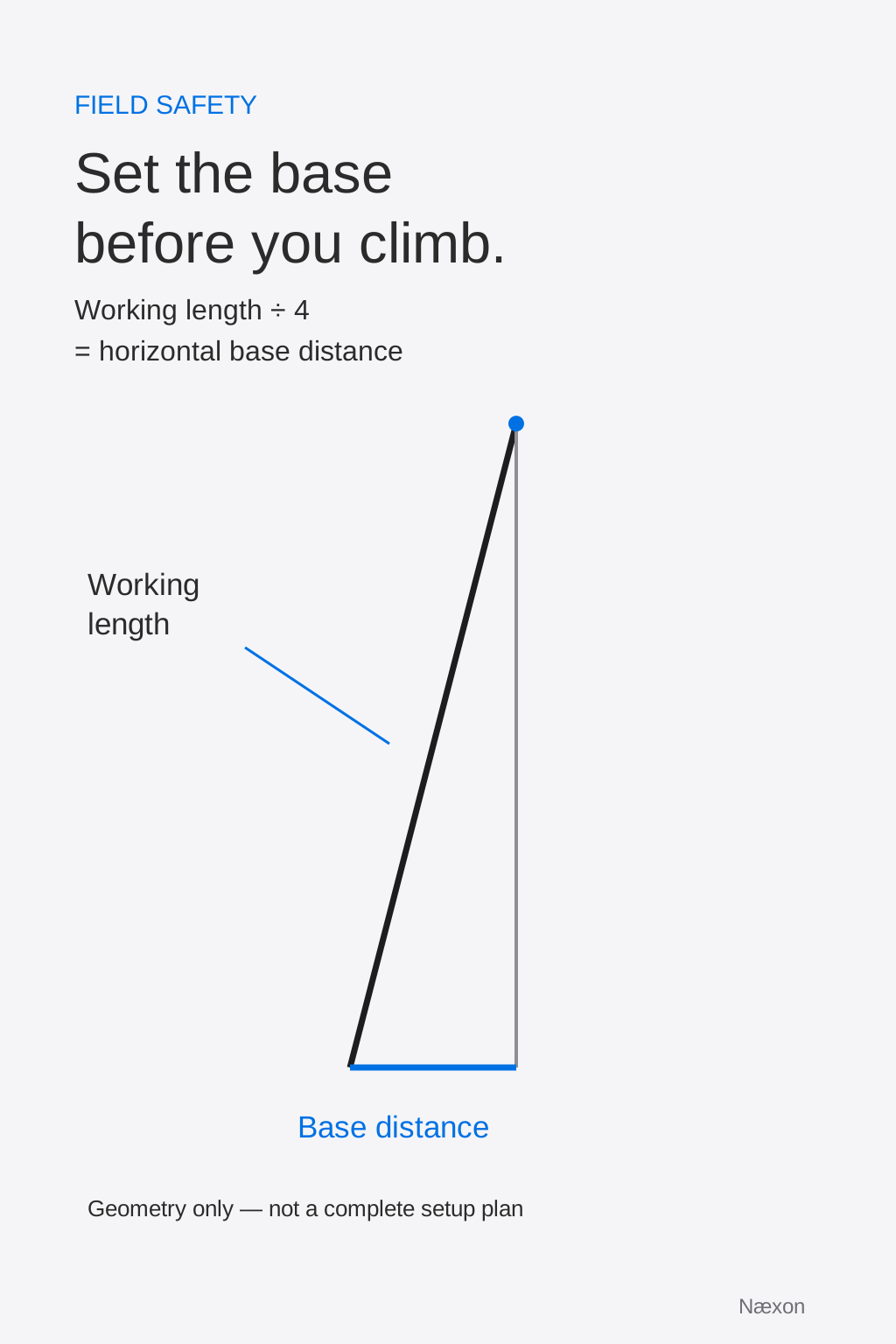
A ladder can look “about right” from ten feet away and still be set too steep or too flat. On a busy jobsite, the error often starts with the wrong measurement. Someone divides the wall height by four, places the feet, and assumes the 4-to-1 rule has been satisfied. OSHA’s construction rule is more precise: for a non-self-supporting ladder, the horizontal distance from the top support to the foot should be approximately one-quarter of the ladder’s working length—the distance measured along the ladder between the foot and the top support.
This lesson covers ordinary portable extension ladders. Wood job-made ladders with spliced side rails have a different OSHA angle rule and are outside this lesson. This lesson turns the extension-ladder requirement into a field calculation. It does not authorize ladder use in a specific location. The employer’s competent person, site rules, the ladder manufacturer’s instructions, the actual access conditions, and applicable regulations control the work.
Working length is not wall height
Three dimensions are easy to confuse. Working length is measured along the ladder from the foot to the point where the ladder bears against its top support. Vertical rise is the height of that support above the feet. Base distance is the horizontal distance from the support line to the feet.
The 4-to-1 relationship uses working length:
Base distance = working length ÷ 4
This creates a right triangle. The ladder is the hypotenuse, not the vertical side. For that reason, dividing the wall height by four is a shortcut, not the stated measurement method. The shortcut gives a nearby number in many ordinary setups, but it is not exact and should not replace the required field check.
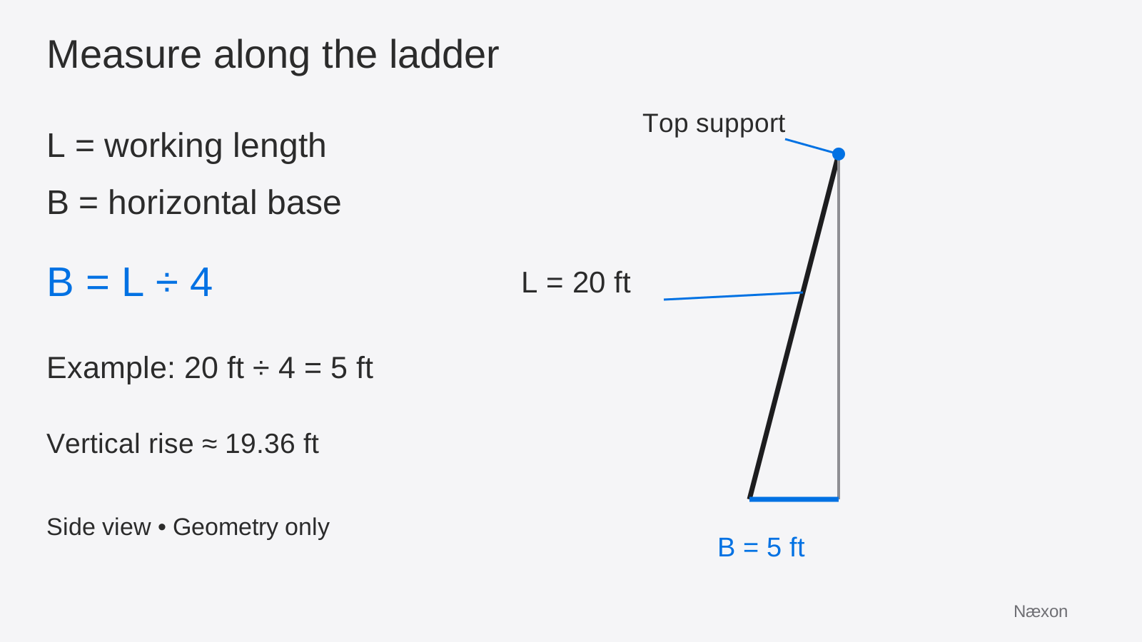
Figure 1. The 4-to-1 relationship uses the working length along the ladder, not the wall height.
Why the angle matters
If the feet are too close to the support, the ladder is too steep. The setup may feel vertical, the climber’s weight can move farther away from the rungs, and the top can be easier to disturb. If the feet are too far out, the ladder is too shallow. The feet can be more likely to slide and the ladder is subjected to a different load direction than intended.
The correct approach is not to make a ladder “look comfortable.” Start with the specified geometry, then verify the surface, support, condition, traffic exposure, electrical hazards, and access arrangement. A correct angle does not make an otherwise unsafe setup acceptable.
OSHA also requires ladders to be used on stable and level surfaces unless secured against displacement. Face the ladder when climbing and use at least one hand to grasp it. Do not carry a load that could make you lose balance. Where the worker or ladder could contact exposed energized electrical equipment, OSHA requires nonconductive side rails; follow the site’s electrical controls. On slippery surfaces, securing or slip-resistant feet are required, and slip-resistant feet do not replace careful placement, lashing, or holding where the surface can remain slippery. In a doorway, passageway, or traffic route, secure the ladder or barricade the area.
Worked example: a 20-foot working length
Assume a non-self-supporting ladder bears against a rigid upper support. The measured working length from the feet to that support is 20 ft. This is an educational example; it is not a ladder selection or approval for a real job.
Let:
- L = working length along the ladder = 20 ft
- B = horizontal base distance
Use:
B = L ÷ 4
Substitute the units:
B = 20 ft ÷ 4 = 5 ft
The approximate horizontal base distance is 5 ft.
An independent geometry check uses the Pythagorean theorem to estimate the vertical rise, V:
V = √(L² − B²)
V = √((20 ft)² − (5 ft)²)
V = √(400 ft² − 25 ft²) = √375 ft² ≈ 19.36 ft
The result is reasonable: the vertical rise is slightly less than the 20-ft ladder working length because the ladder is leaning. The implied angle is approximately 75.5 degrees from horizontal, which agrees with the geometry associated with a one-quarter base distance.
Do not round the setup into a different arrangement merely because the calculated number is inconvenient. If the necessary footprint is obstructed, exposed to traffic, unstable, or otherwise unsuitable, stop and use an approved alternative access method.
Accessing an upper landing
When a portable ladder is used to access an upper landing, OSHA requires its side rails to extend at least 3 ft above the landing. If that extension is not possible because of ladder length, the ladder must be secured at the top to a rigid support that will not deflect, and a grasping device such as a grabrail must be provided. The ladder extension must not deflect under a load in a way that would itself cause the ladder to slip off its support.
That 3-ft extension is not part of the working-length segment used in the 4-to-1 calculation when the top support is at the landing edge. Measure the working length to the bearing point, then separately verify the rail extension above the landing. Do not simply add the landing extension to the wall height and divide the total by four.
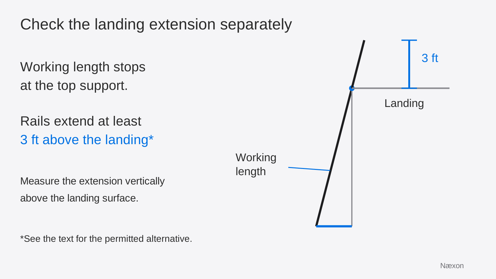
Figure 2. Measure the 4-to-1 working length to the top support; verify the required access extension as a separate condition.
A practical setup sequence
- Confirm the ladder is suitable. Read its labels and manufacturer instructions. Verify its length, rated capacity, material, and intended use for the task. Do not exceed the manufacturer’s rated capacity or maximum intended load.
- Inspect before setup. Look for broken or missing rungs, split or damaged rails, corrosion, defective hardware, contamination, or other visible defects. A defective ladder must be identified and withdrawn from service according to the applicable procedure.
- Evaluate the location. Check the ground, top support, overhead conditions, electrical exposure, traffic, doors, equipment movement, and clear space at the top and bottom.
- Establish the top support. Both rails should be supported equally unless the ladder has a designed single-support attachment.
- Measure working length. Measure along the ladder between the foot and the top support. Do not substitute total ladder length or wall height.
- Calculate the base distance. Divide the measured working length by four. Carry the same units through the calculation.
- Place and secure the ladder. Follow site requirements and manufacturer instructions. Correct geometry does not eliminate the need to prevent displacement.
- Verify upper-landing access. When the ladder provides access to a landing, check the rail extension or the permitted secured-ladder and grabrail alternative.
- Conduct a final stop check. If the ground settles, traffic control changes, support shifts, weather affects the surface, or any condition becomes uncertain, keep the ladder out of service until a qualified person resolves it.
Troubleshooting a setup that will not work
If the calculated feet location lands in a walkway or vehicle route, do not pull the base closer merely to make room. The geometry is telling you the selected access point may be unsuitable. Relocate the access under the approved plan, isolate the area, or select another approved access system.
If both rails will not contact the upper support equally, do not shim one rail with loose material. Reposition the ladder or use a manufacturer-approved attachment designed for the support condition.
If the feet rock, the surface is not providing stable, level support. Do not assume a person standing on the bottom rung is a permanent control. Stop and correct the foundation or use an approved securing method under the responsible person’s direction.
If the ladder reaches the landing but the rails do not provide the required extension, a longer ladder may be necessary. Do not create length by tying ladders together unless they are specifically designed for that use.
If the ladder angle changes after someone climbs, suspect displacement, flexing support, settlement, or loss of restraint. Stop use immediately. The task has moved beyond a simple tape-measure correction and requires competent supervision.
Common mistakes
The most common math error is dividing the wall height by four. The correct input is working length along the ladder to its top support. A second error is using the ladder’s full labeled length even when the top support is lower. The unused rail above the support does not belong in that working-length segment.
Another mistake is treating the 4-to-1 calculation as the entire inspection. Angle is only one condition. Stable footing, equal rail support, cleanliness, rated capacity, electrical suitability, traffic control, defects, and manufacturer instructions still matter.
Finally, workers sometimes measure diagonally from the wall to the feet and call that the base distance. Base distance is horizontal. The ladder itself is the diagonal.
Field Rules
- Use working length along the ladder—not wall height—in the 4-to-1 calculation.
- Measure base distance horizontally from the top-support line to the feet.
- Check upper-landing rail extension separately from the working-length calculation.
- Never correct an obstructed footprint by making the ladder steeper.
- A correct angle does not excuse poor footing, traffic exposure, damage, overload, or electrical hazards.
- Stop when the setup changes or cannot match the approved conditions.
Knowledge Check
- A ladder’s measured working length is 24 ft. What approximate base distance does the 4-to-1 relationship give?
- A worker divides a 16-ft wall height by four without measuring along the ladder. What is wrong with the method?
- The calculated feet location lands in an active doorway. What is the first principle to apply?
- A ladder used for access extends only 18 in above the landing and no permitted alternative arrangement is provided. Is the setup complete?
- Both rails contact the support, but one foot rocks on loose material. Does the correct angle make the setup acceptable?
Answers
- 6 ft. Divide 24 ft by 4; the units remain feet.
- It uses the wrong variable. OSHA’s relationship is based on working length along the ladder between the foot and top support, not vertical wall height.
- Do not alter the angle to fit. Secure or barricade the traffic area as required, relocate the approved access, or use another approved method.
- No. Upper-landing access requires the specified rail extension or the permitted secured-ladder and grasping-device alternative.
- No. The surface must provide stable, level support unless the ladder is properly secured against displacement. Stop and correct the footing under the applicable procedure.
Practical Exercise
On paper, draw a right triangle representing a ladder with an 18-ft working length. Calculate the base distance:
B = 18 ft ÷ 4 = 4.5 ft = 4 ft 6 in
Then estimate the vertical rise:
V = √(18² − 4.5²) = √303.75 ≈ 17.43 ft
Check the result by confirming that the rise is less than the ladder working length and that the base distance is exactly one-quarter of that working length. Finally, label the top support, working length, base distance, and any rail extension above an imagined landing. Keep this as a drawing exercise; do not set or climb a ladder without authorized supervision and site controls.
Related learning
The geometry method builds naturally on Næxon’s field formulas for scaffold builders. For nearby access-area fundamentals, review how scaffold foundations carry loads and how a crew diagnoses a scaffold bay that will not stay square. These lessons support field recognition, but approved plans, manufacturer instructions, site procedures, and qualified supervision control the actual work.