Næxon Learning Center · Crane and heavy-equipment operators · Fundamentals · Apprentice · 8-minute read
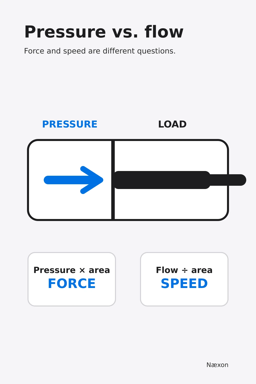
What you will learn: how pressure relates to available cylinder force, how flow relates to actuator speed, why pressure appears only when the circuit meets resistance, and how to reason through a slow or weak hydraulic function without guessing at adjustments.
A boom raises slowly, so someone says the machine needs “more pressure.” Another function stalls under load, so someone blames low flow. Those diagnoses sound interchangeable, but they describe different hydraulic quantities. Confusing them can waste troubleshooting time and can tempt an operator toward an unsafe adjustment.
This lesson separates the two ideas. Pressure is force per unit area. Flow is a volume moving per unit time. In a simple cylinder circuit, pressure and effective piston area determine theoretical force, while flow and effective area determine theoretical speed. Real machines add losses, controls, load-sensing logic, temperature effects, leakage, and manufacturer-set limits, but the distinction remains the starting point.
Pressure is not something a pump stores in the oil
A pump moves fluid. Pressure develops when that flow meets resistance: a load at a cylinder, restriction through a valve or hose, or another force opposing motion. With very little resistance, the pump may circulate considerable flow while the pressure remains relatively low. As resistance increases, pressure rises until the load moves, a control changes state, or a relief or compensating device limits pressure.
Pressure is written as force divided by area:
P = F ÷ A
Rearranged for a cylinder, the theoretical force is:
F = P × A
In U.S. customary units, pounds per square inch multiplied by square inches produces pounds-force. This is a theoretical relationship. Actual usable force is lower because friction, seal drag, backpressure, geometry, component efficiency, and dynamic effects matter. The equipment load chart, service information, control settings, and manufacturer procedures govern the real machine.
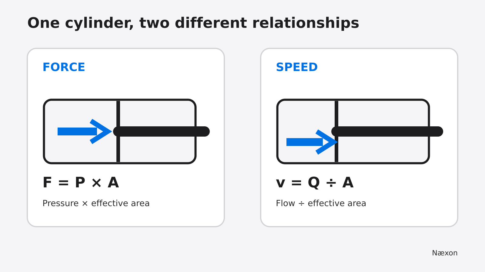
Figure 1. Pressure acting on effective piston area establishes theoretical cylinder force; flow filling that volume establishes theoretical speed. The two relationships answer different questions.
Flow answers the speed question
Flow is the volume delivered in a given time. If a cylinder receives more flow and its effective area stays the same, the piston moves faster. If the same flow is sent to a cylinder with a larger effective area, the piston moves more slowly because more fluid volume is required for each inch of travel.
The ideal relationship is:
v = Q ÷ A
where v is piston speed, Q is volumetric flow, and A is effective piston area. The units must match. A flow in cubic inches per second divided by square inches produces inches per second. If flow is given in gallons per minute, convert it before using square-inch area.
One U.S. gallon contains 231 cubic inches, so:
Q (in³/s) = Q (gal/min) × 231 ÷ 60
The relationship is ideal and steady-state. Acceleration, compressibility, leakage, valve metering, pump controls, and load interaction can change observed speed.
A worked example: one cylinder, two separate answers
Assume a training example with a double-acting cylinder extending on its full-bore side. The illustrative bore diameter is 4.00 inches, the measured supply pressure during the loaded portion of the stroke is 2,000 psi, and the measured inlet flow is 8.0 U.S. gallons per minute. These are not instructions or acceptable limits for any specific machine.
First find the full-bore piston area:
A = πd² ÷ 4
A = π × (4.00 in)² ÷ 4 = 12.566 in²
The ideal extension force is:
F = P × A = 2,000 lbf/in² × 12.566 in² = 25,132 lbf
Rounded appropriately, that is about 25,100 pounds-force, or 12.6 short tons-force because 25,132 ÷ 2,000 = 12.566. This is theoretical force at the piston, not the allowable lifted load and not a substitute for a machine capacity chart.
Now convert the flow:
Q = 8.0 gal/min × 231 in³/gal ÷ 60 s/min = 30.8 in³/s
Then find the ideal extension speed:
v = Q ÷ A = 30.8 in³/s ÷ 12.566 in² = 2.45 in/s
An independent check multiplies the calculated speed by area: 2.45 in/s × 12.566 in² = 30.79 in³/s, which matches the converted flow within rounding. A reasonableness check also helps: a 12.566-square-inch piston needs 12.566 cubic inches for every inch of travel, so roughly 31 cubic inches each second should move it a little under 2.5 inches each second.
You can verify unit conversions and repeat the arithmetic with the Numerus trade calculator, while still using actual machine data and approved procedures.
Correct diagnosis starts with the symptom
A slow function and a weak function are not the same complaint. “Slow” describes rate of movement. “Weak” usually means the actuator cannot overcome the applied load, though linkage geometry, stability controls, or structural limits may also be involved.
The common incorrect approach is to treat every slow function as a pressure problem. Turning up a pressure control does not directly create more flow. It may exceed a safe or approved setting, increase heat, mask another fault, or damage components. The correct approach is to identify whether the symptom is speed, force, erratic motion, drift, noise, or heat; then follow the manufacturer’s test conditions and diagnostic sequence.
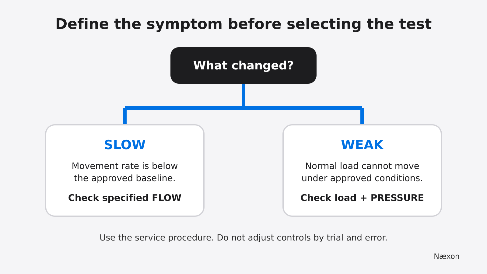
Figure 2. Separate speed symptoms from load-moving symptoms before selecting tests. Pressure and flow readings only mean something when taken at the specified ports, temperature, speed, control command, and load condition.
A field method for thinking before testing
- Make the machine safe. Park, lower or mechanically support raised components as required, remove the load when directed, and follow the equipment-specific energy-control procedure. Hydraulic pressure can remain after the engine or motor stops.
- Define the exact symptom. Record which function, direction, load, engine speed, oil temperature, and control position produce the problem. “Boom slow when warm while lowering” is more useful than “hydraulics weak.”
- Compare like with like. Check whether other functions supplied by the same pump or section behave normally under equivalent approved conditions. Shared symptoms and isolated symptoms point the diagnostic process in different directions.
- Use specified test points and conditions. Qualified personnel should follow the service manual for gauges, flow meters, rated hoses, temperature, engine speed, control commands, and load. Never loosen a fitting to judge pressure or flow.
- Interpret pressure and flow separately. A pressure reading shows resistance at that point under that condition. A flow reading shows delivered volume at that point under that condition. Neither alone proves the failed component.
- Stop at the authorization boundary. Relief, compensator, load-sensing, counterbalance, and motion-control adjustments are not trial-and-error operator settings. Escalate when the procedure calls for trained service personnel or engineered support.
For a refresher on how mechanical pressure becomes a dial indication, see how a Bourdon-tube pressure gauge works. The gauge can report pressure at its connection; it does not identify the cause by itself.
Troubleshooting patterns without jumping to conclusions
If one function is slow but still develops normal specified pressure under a controlled test, possible categories include insufficient commanded flow, valve metering, internal leakage, excessive backpressure, mechanical binding, or a control-system limit. The correct next check depends on the schematic and service procedure.
If several functions are slow, look for what they share: pump supply, prime, drive speed, fluid condition, suction restrictions, temperature, or a control signal. That is a troubleshooting direction, not a component verdict. A machine can reach high pressure with very little flow, so a high-pressure reading does not prove that pump delivery is healthy.
If a function moves at normal speed unloaded but stalls early under load, the force side of the problem deserves attention. Confirm that the applied load and geometry are within the machine’s approved capacity, then follow the specified pressure and leakage tests. Do not use a blocked or overloaded actuator as a casual pressure test.
If motion is jerky, noisy, or accompanied by heat, stop treating the complaint as a simple pressure-versus-flow calculation. Aeration, cavitation, contamination, unstable controls, damaged components, excessive restriction, or mechanical problems can require immediate shutdown and qualified diagnosis.
The centrifugal-pump field guide is useful related learning, but do not transfer centrifugal-pump rules directly to positive-displacement hydraulic circuits. The machines move fluid by different principles and use different controls.
Common mistakes
One mistake is reading a gauge with the function unloaded and concluding that the system cannot build pressure. Without resistance, low pressure may be normal. Another is seeing rated flow on a pump label and assuming the actuator receives that flow under every operating condition. Pump speed, control logic, leakage, and circuit routing influence delivered flow.
A third mistake is calculating cylinder force from outside barrel diameter instead of effective piston area. The necessary area comes from the internal working geometry, and retract force uses annular area because the rod occupies part of the piston face. Manufacturer data should control when dimensions are not known.
The most serious mistake is opening a line or touching a suspected leak. High-pressure fluid can penetrate skin, and stored hydraulic energy can move a machine after its prime mover is off. Follow the employer’s energy-control procedure, restrain elevated members, dissipate or control stored energy, and verify isolation before servicing.
Field Rules
- Pressure relates to force; flow relates to speed.
- A pump supplies flow, while resistance causes pressure to rise.
- High pressure does not prove adequate flow, and low no-load pressure does not prove a weak system.
- Calculate with effective area and compatible units.
- Never adjust a hydraulic control or open a line as a diagnostic shortcut.
- Approved load charts, schematics, service procedures, and qualified supervision control the work.
Knowledge Check
- A cylinder reaches the specified loaded pressure but moves much slower than the approved baseline. Which quantity should the diagnostic process measure next: flow or a higher pressure setting?
- A 3.00-inch-bore cylinder acts on its full-bore side at 1,500 psi. What is the ideal force?
- Why can a gauge show low pressure while an unloaded actuator is moving normally?
- A pump is switched off, but a raised attachment remains supported by the hydraulic system. Is the equipment automatically safe to service?
Answers
- Measure flow under the specified conditions. The symptom is speed, and increasing a pressure setting is not a valid substitute for a flow test.
- About 10,600 lbf. Area = π × 3.00² ÷ 4 = 7.069 in². Force = 1,500 lbf/in² × 7.069 in² = 10,603 lbf, before losses. This is not an allowable lifting capacity.
- Pressure rises with resistance. An unloaded actuator may require little force, so it can move with relatively low pressure even when substantial flow is present.
- No. Hydraulic and gravitational energy remain possible. The equipment-specific procedure must address isolation, blocking or restraint, pressure dissipation, and verification.
Practical Exercise
On paper, draw two identical 4-inch-bore cylinders. Label one “same pressure, double flow” and the other “double pressure, same flow.” Starting from the worked example, calculate the ideal force and speed for each case. The expected check is: doubling flow doubles ideal speed but leaves the pressure-based force unchanged; doubling pressure doubles ideal force but leaves the flow-based speed unchanged. Discuss with a qualified trainer why real equipment controls and ratings may prevent either theoretical change from occurring.
For the next step, study how a hydrotest pump develops pressure and compare that pressure-limited process with motion control in a mobile hydraulic circuit. Keep the distinction clear: similar units do not make the applications interchangeable.