Morning Edition · Crane and heavy-equipment operators · Apprentice · Fundamentals · 9-minute read
What you will learn: Identify crane load radius, distinguish it from boom length, calculate radius from plan-view offsets, and explain why the exact manufacturer load chart must control every capacity decision.
The hook is over the pick point, the boom is long enough, and the load appears to be within reach. Then someone asks a question that changes the entire lift discussion: what is the operating radius? A few feet of difference can move the job to a different part of the crane's load chart, even when the load itself has not changed.
Load radius is a foundation for reading crane capacity information. This lesson explains the geometry and a safe method for checking it. It does not determine whether a real lift is approved. The exact crane, configuration, load chart, operating instructions, engineered lift plan, site conditions, and qualified supervision always control.
What load radius actually measures
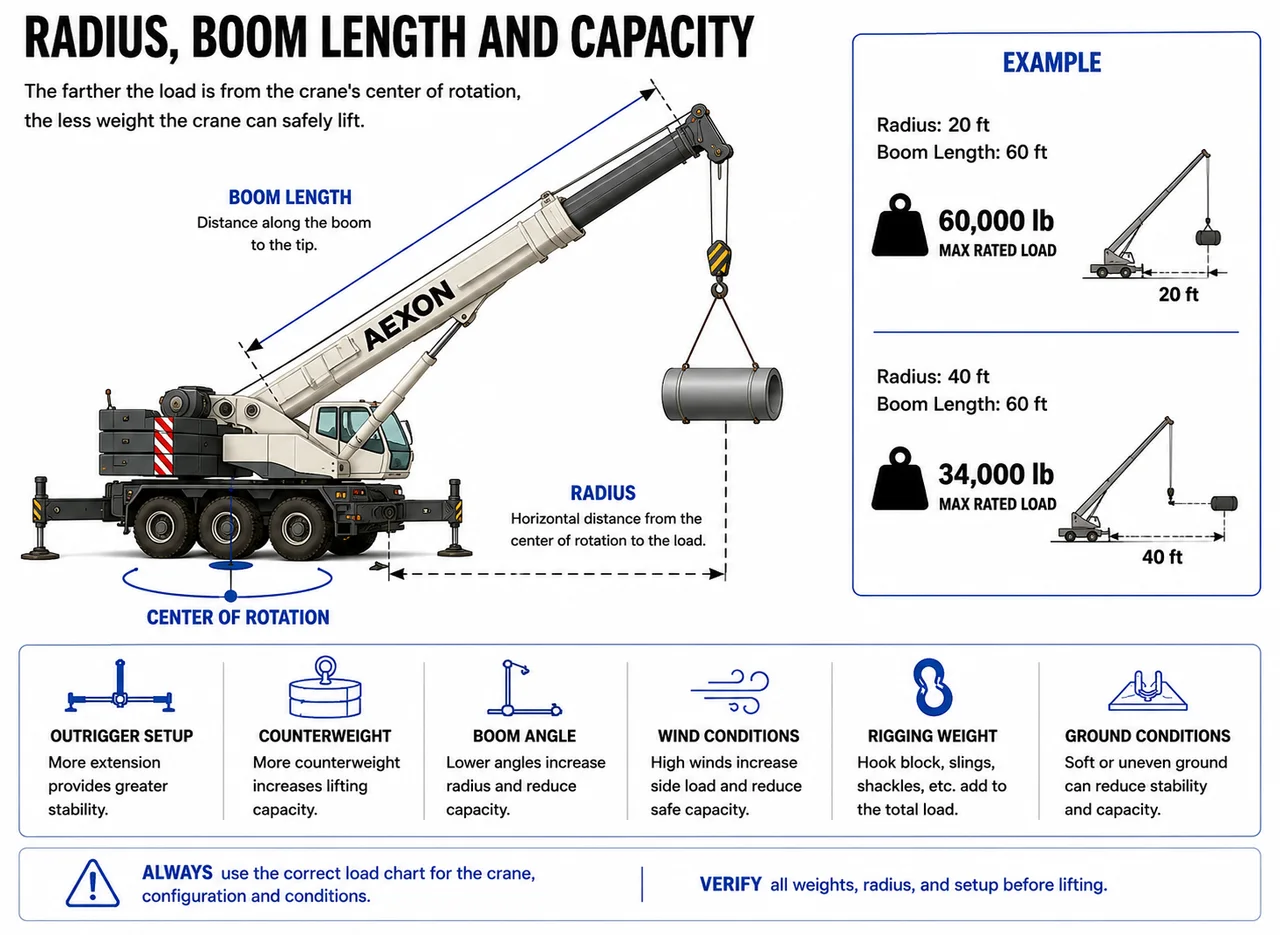
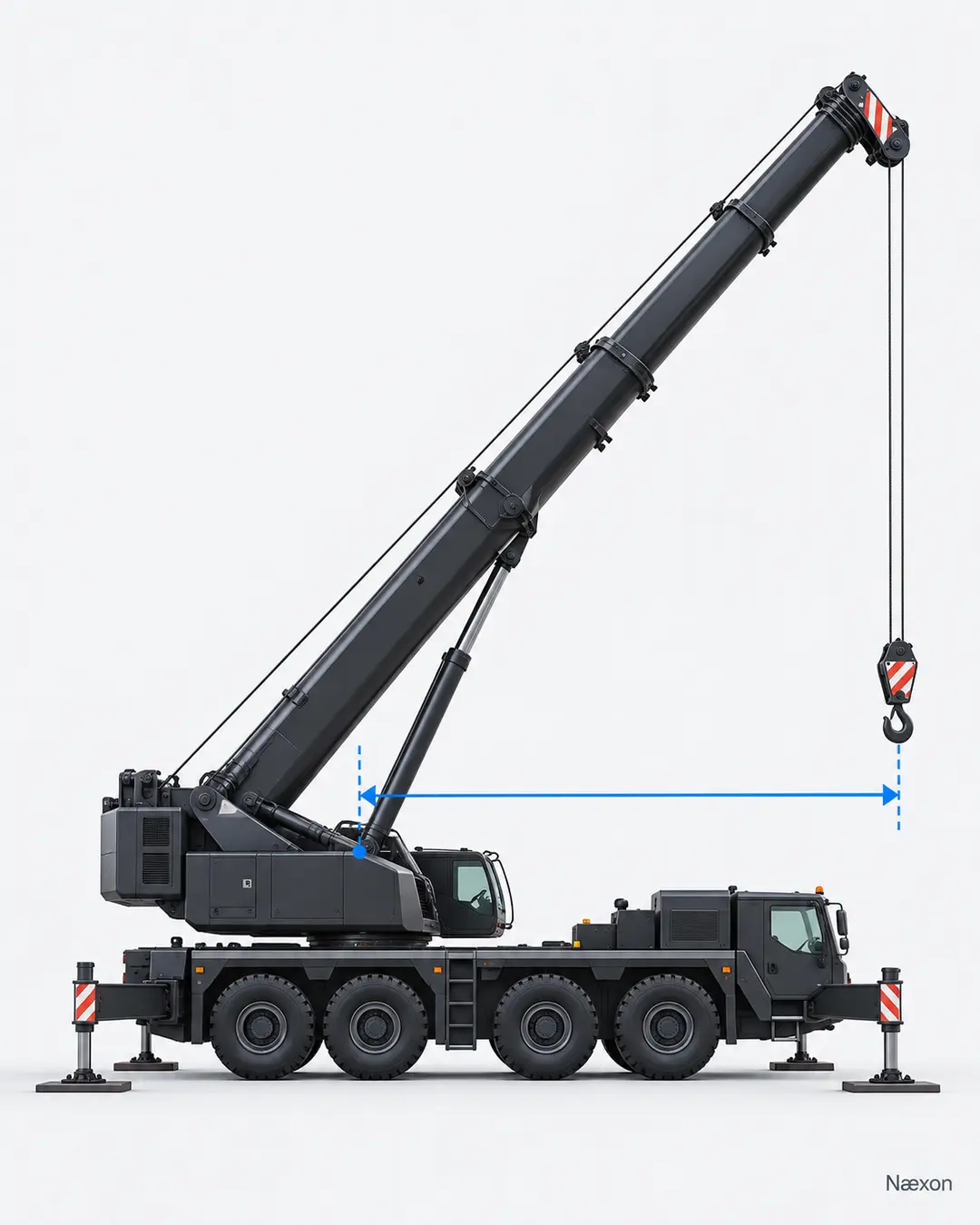
For a mobile crane, load radius is generally the horizontal distance from the crane's axis of rotation to the center of the vertical hoist line or lifting device, using the precise definition supplied with that crane's chart. Some manufacturers describe operating radius with the load applied; chart notes may also distinguish loaded boom angle from other indicated geometry. Read the definitions printed on the chart in the cab.
Three words matter: horizontal, rotation, and vertical. The starting point is not an outrigger pad, bumper, boom foot pin, or edge of the carrier. The ending point is not the load's nearest edge. It is the centerline of the hanging hoist line. Figure 1 shows the measurement in side elevation.
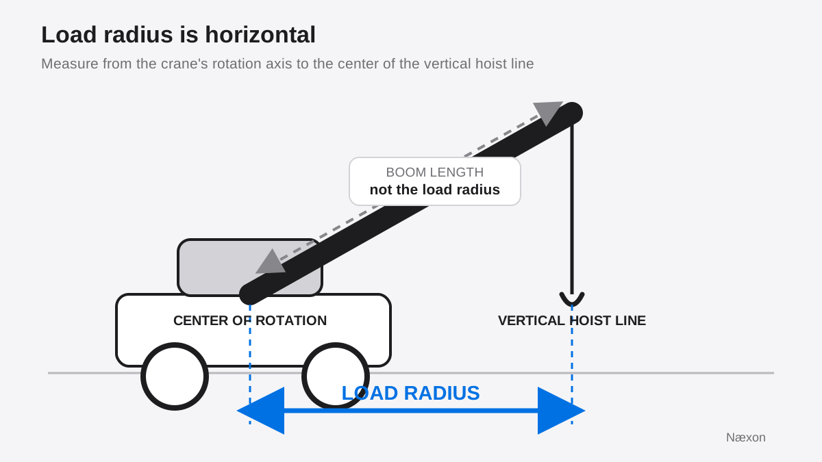
A common incorrect approach is to use boom length as radius. That fails because the boom is normally inclined. Boom length follows the diagonal structure, while radius is only its horizontal reach to the hoist line. The error is easy to recognize: if the tape or drawing dimension follows the boom, it is not a direct radius measurement. The correct result is a level plan or horizontal dimension tied to the rotation axis and hoist line.
Why capacity changes as radius increases
A suspended load creates an overturning effect about the crane. A simple way to understand the trend is moment: load multiplied by horizontal radius. Moving the same load farther from the axis increases that moment. For example, an illustrative 8,000-pound load at 20 feet creates 160,000 pound-feet of load moment; at 30 feet it creates 240,000 pound-feet, a 50% increase.
That comparison explains direction, not allowable capacity. A crane is not a simple lever with one universal limit. Structural strength, stability, boom configuration, working area, counterweight, outrigger or crawler setup, reeving, attachments, deductions, ground conditions, and manufacturer restrictions all matter. Never calculate an allowable load by dividing a guessed moment limit by radius. Use the exact chart and instructions for the machine.
Radius can also change during a lift. Boom deflection under load, booming down, telescoping, swinging through uneven setup, or allowing the load to drift can move the hoist line outward. The operator and lift team therefore care about the maximum planned radius and the path, not merely the radius at the pick. Capacity must remain adequate through every phase required by the approved plan.
From geometry to the correct chart location
Load charts are configuration-specific. Before finding a capacity, identify the crane model and serial-specific information, boom or jib arrangement, counterweight, support configuration, working area, parts of line, and all chart notes and deductions. A number taken from a similar crane or a product brochure is not a substitute for the chart supplied with the machine.
Boom length and boom angle help describe the crane's geometry, but they do not replace an accurate radius. Indicators and rated-capacity systems are operating aids. They must be used as the manufacturer intends and do not excuse an incorrect setup, an unknown load, or a misread chart.
Once the actual radius is established, locate that value in the correct chart section and follow its instructions. Do not invent a capacity between printed radii or interpolate unless the manufacturer expressly provides that method. If the measured radius, configuration, load weight, deductions, or planned path is uncertain, stop the lift-planning decision and escalate to the competent or qualified people responsible for it.
Worked example: radius from two plan offsets
Suppose a training drawing locates the center of rotation at the origin. The vertical hoist line is 18 feet forward and 24 feet to the side in plan view. These are illustrative coordinates, not approved site dimensions. Assume the offsets are perpendicular, lie in one horizontal plane, and are measured from the same crane centerline reference.
Let x equal the 18-foot forward offset, y equal the 24-foot side offset, and R equal the horizontal radius. The offsets form the legs of a right triangle, so:
R = √(x² + y²)
Substitute the values and carry units through the calculation:
R = √[(18 ft)² + (24 ft)²] = √(324 ft² + 576 ft²) = √900 ft² = 30 ft
No rounding is needed because the square root is exact. An independent reverse check gives 30² = 900 and 18² + 24² = 324 + 576 = 900. A reasonableness check also works: the radius must be longer than either 18-foot or 24-foot leg but shorter than their 42-foot sum. Thirty feet fits that range.
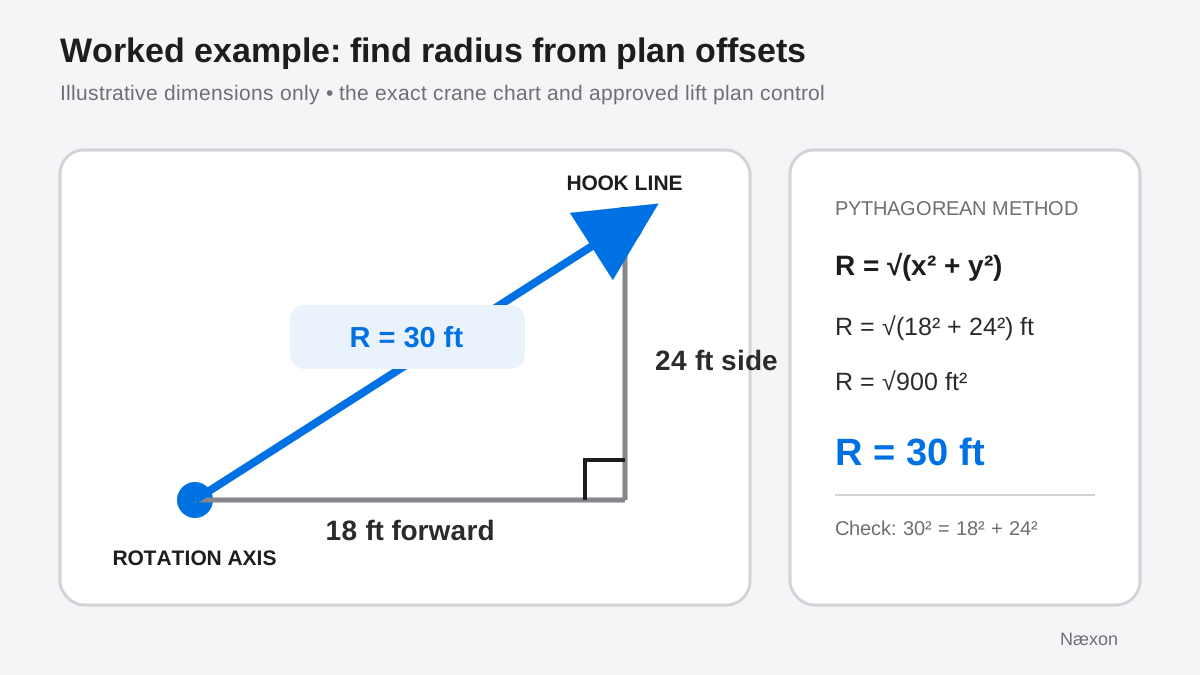
The 30-foot result is an input to chart reading, not a capacity answer. The next step is to use the exact crane chart and applicable configuration. The example says nothing about whether a particular load is permitted at that radius.
A practical radius-checking sequence
- Confirm the reference. Identify the crane's axis of rotation and the center of the vertical hoist line from the manufacturer's definitions and approved lift information.
- Confirm the configuration. Match the exact boom, attachment, counterweight, support setup, working area, reeving, and deductions to the correct chart section.
- Establish the planned path. Consider pick, travel if permitted, swing, set, and any point where the load could reach its greatest radius.
- Determine radius. Use the crane's approved indication, a verified drawing, or an authorized field-measurement method. Treat plan coordinates consistently and keep units aligned.
- Read the chart exactly. Apply all notes, limitations, and deductions. Do not round toward a more favorable capacity or assume an unprinted value.
- Cross-check before lifting. Compare the planned value with the operator's indications and lift plan. Stop if the machine, chart, load, radius, or configuration does not agree.
Troubleshooting a radius that does not agree
The drawing and crane display disagree: first verify that both use the same reference point and units. Check whether one value is a planned unloaded position while the other reflects the loaded crane. Confirm the crane is level and configured as documented. Do not adjust or bypass an indicator to make the numbers match.
The radius grows after the load clears: boom deflection or load movement may have shifted the hoist line outward. Hold the load only under approved conditions, avoid further outward movement, and follow the operator's and lift director's instructions. If capacity margin or path is uncertain, land the load in a safe controlled manner under the plan and escalate.
The indicated radius jumps or appears implausible: compare it with known geometry and the equipment's required checks. A sensor, setup, or configuration-input problem may exist. Stop using the value for a capacity decision until the authorized inspection or troubleshooting process resolves it.
The chart has no obvious match: do not select the nearest more favorable row. Recheck the chart section, working area, configuration, and notes. When the chart does not clearly cover the condition, the correct action is to stop and obtain manufacturer or qualified-person direction.
Common mistakes
Measuring from the carrier edge or an outrigger shortens the apparent radius and breaks the chart's reference system. Measuring to the near side of a large load ignores that the hoist line defines the working point. Reading boom length as radius confuses a diagonal with a horizontal dimension. Using the pick radius for the entire lift misses a larger radius at swing or set. Finally, treating a rated-capacity indicator as permission to proceed mistakes an aid for the complete planning process.
Field Rules
- Radius runs horizontally from the rotation axis to the vertical hoist line.
- Boom length and boom angle are not substitutes for load radius.
- Plan for the greatest radius along the approved load path.
- Use the serial-specific chart, exact configuration, notes, and deductions.
- When references or readings disagree, stop and resolve the discrepancy.
Knowledge Check
- A worker measures 52 feet along the boom and calls it a 52-foot radius. What is wrong with that conclusion?
- In a plan view, the hoist line is 15 feet forward and 20 feet sideways from the rotation axis. What is the radius?
- The load is within the chart at the pick point, but the set point is farther from the crane. Which radius must the lift team evaluate?
- The rated-capacity display and approved drawing disagree by several feet. What is the next step?
Answers
1. The measurement follows the diagonal boom. Radius is the horizontal distance from the rotation axis to the vertical hoist line, so the value must be established with the correct horizontal reference.
2. R = √(15² + 20²) ft = √625 ft² = 25 ft. The reverse check is 25² = 15² + 20².
3. The team must evaluate the maximum planned radius throughout the whole load path, including the farther set point. A permitted pick condition does not automatically cover a larger radius later.
4. Stop the capacity decision and reconcile the references using the exact crane instructions, configuration, approved plan, and qualified supervision. Do not choose whichever number gives more capacity.
Practical Exercise
On paper, mark a crane rotation axis at coordinate (0, 0) and three possible hoist-line positions: A at (12 ft, 16 ft), B at (18 ft, 24 ft), and C at (21 ft, 20 ft). Calculate each horizontal radius with R = √(x² + y²), then identify the greatest planned radius. Expected results are A = 20 ft, B = 30 ft, and C = 29 ft because √841 = 29. Position B governs this geometry exercise at 30 ft. Do not use these values to authorize a real lift; the equipment chart and approved plan remain essential.
Related learning
Before applying radius to a real pick, review crane hand signals for lift-team communication. Continue with field formulas for riggers, then practice the distinct calculation in the sling length and rise method. The lesson on why suspended loads start rotating is a useful next step for understanding load behavior after the pick.