Evening Edition · Crane and heavy-equipment operators · Intermediate · Math · 10-minute read
What you will learn: Build a complete suspended-load ledger, subtract hook block, rigging, lifting-device, and required attachment weights from the applicable chart rating, and recognize when missing information stops the calculation.
The lift plan identifies a 31,500-pound vessel. The correct crane configuration and radius have been selected, and the applicable load-chart cell shows 40,000 pounds. At first glance, the lift appears to fit. Then someone asks a better question: does that 31,500 pounds include the hook block, slings, shackles, spreader beam, and every deduction required by the crane's chart notes?
A crane supports more than the object being moved. Everything hanging from the boom point contributes to the suspended load. Depending on the manufacturer's chart language and installed configuration, attachments may require additional deductions even when they are not carrying the load directly. Forgetting those items can turn an apparently acceptable number into an overload.
This lesson begins after the crew has identified the correct crane, configuration, boom length, load radius, and applicable chart cell. If that work is not complete, review how load radius selects crane capacity first. The exact serial-specific load chart, notes, operator manual, lift plan, and qualified supervision always control the real lift.
Rated chart value is not automatically payload capacity
Crane manufacturers commonly state that their rated loads apply to freely suspended loads under specified configurations and conditions. They also commonly direct the user to count hooks, hook blocks, slings, and other lifting devices as part of the total load. The terminology and exact deduction method vary, so operators must use the chart and notes for the actual machine rather than a remembered rule from another crane.
In this lesson, C means the rated load shown in the applicable chart cell. Wavailable means the weight that remains available for the object being lifted after all required subtractions. The general bookkeeping relationship is:
Wavailable = C − (Wblock + Wrigging + Wdevice + Dattachment)
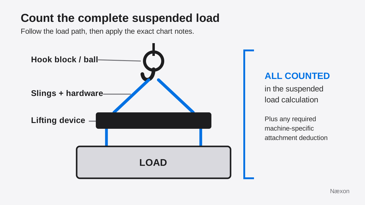
The terms inside the parentheses are the hook block or overhaul ball, slings and connecting hardware, below-the-hook lifting devices such as a spreader beam, and any attachment deduction required by the exact manufacturer chart. Not every chart uses these labels, and a chart may handle an installed jib, auxiliary boom head, or other attachment differently. Follow its notes exactly and avoid both omission and double-counting.
Start with the correct chart cell
A clean subtraction cannot repair a bad chart selection. Confirm the crane model and serial-specific rating information, counterweight, boom and jib configuration, outrigger or track condition, reeving, operating sector, boom length, and load radius. The crane must be set up and operated within the conditions stated by the manufacturer and the approved lift plan.
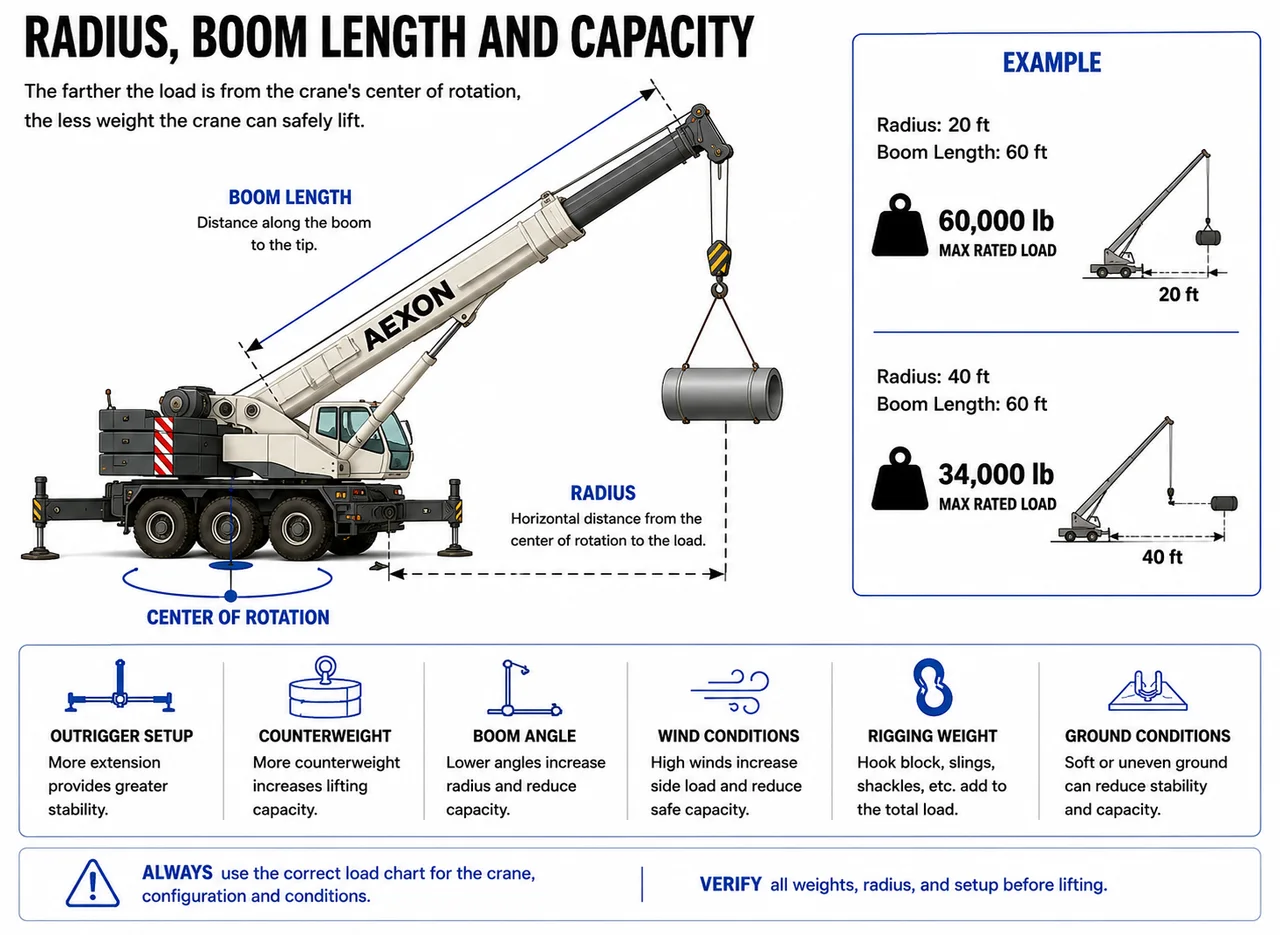
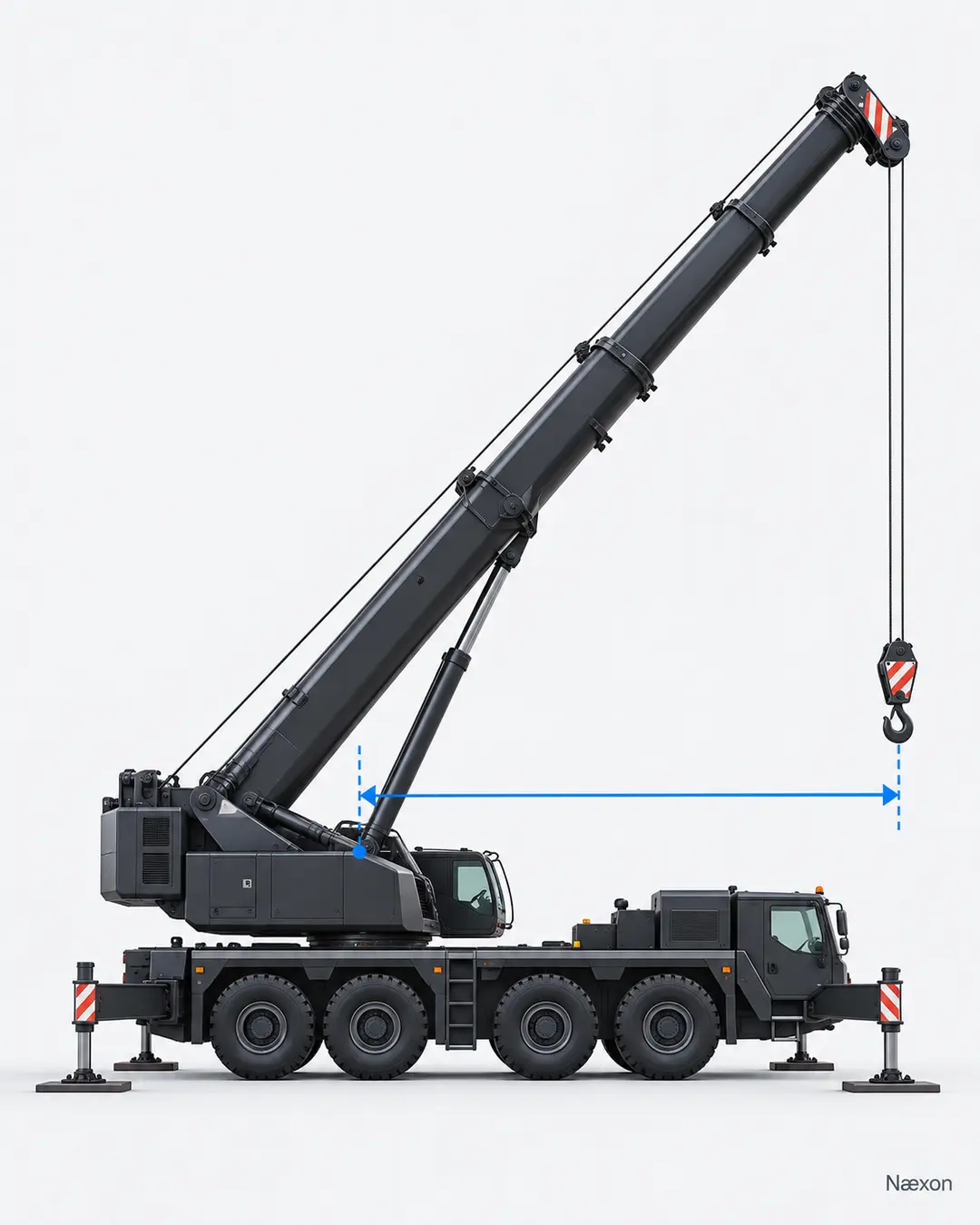
Radius deserves special attention because it is measured from the crane's axis of rotation to the vertical line through the suspended load, not to the load's near edge. Radius can increase as a load moves, the boom deflects, or the load swings. Use the greatest applicable planned radius, not the most favorable moment in the pick.
Once the correct chart cell is found, read every note attached to that configuration. A value in the table does not cancel notes about parts of line, attachment deductions, operating areas, boom angles, structural limits, stability limits, wind, ground support, or prohibited areas. If no capacity is listed for the intended condition, do not interpolate a rating.
Build a suspended-load ledger
The safest arithmetic starts with a written inventory. Record the verified weight source beside each item: manufacturer data plate, rigging certificate, approved drawing, engineered calculation, or another reliable source accepted by the lift procedure. Do not estimate a block, beam, or sling assembly by appearance.
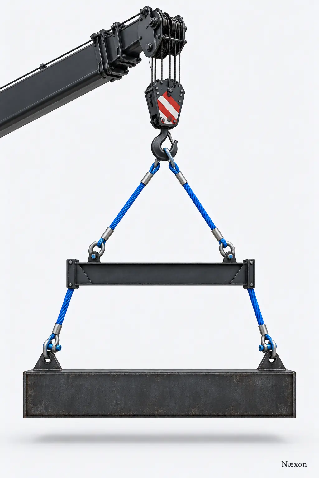
Begin with the object being lifted, including any contents, temporary steel, internal water, attached piping, transport frames, or other material that will leave the ground with it. Then add the hook block or overhaul ball, slings, shackles, master links, swivels, equalizer plates, spreader bars, lifting beams, magnets, grabs, personnel platforms, or other below-the-hook devices actually suspended.
Finally, inspect the crane chart notes for machine-specific deductions. An erected but unused attachment may still change the available rating. Some charts require a stated deduction; others provide a different rating table or configuration designation. Never copy a deduction value from another model, boom arrangement, or chart revision.
Worked example: from chart rating to load allowance
Assume a paper exercise in which the correct configuration, radius, and chart cell have already been verified. The applicable chart rating is C = 40,000 lb. The hook block weighs 1,900 lb; the slings and connecting hardware weigh 700 lb; the spreader beam weighs 2,500 lb; and the exact chart notes require a 900 lb attachment deduction.
These are illustrative training values, not specifications for any crane or lift. First total the deductions:
Wdeductions = 1,900 lb + 700 lb + 2,500 lb + 900 lb = 6,000 lb
Then calculate the remaining allowable load weight:
Wavailable = 40,000 lb − 6,000 lb = 34,000 lb
The proposed object weighs 31,500 pounds, which is 2,500 pounds below the arithmetic remainder. That difference is not automatic approval. It does not account for an incorrect radius, unverified load weight, dynamic effects, wind, ground conditions, configuration errors, or any project requirement for additional planning margin.
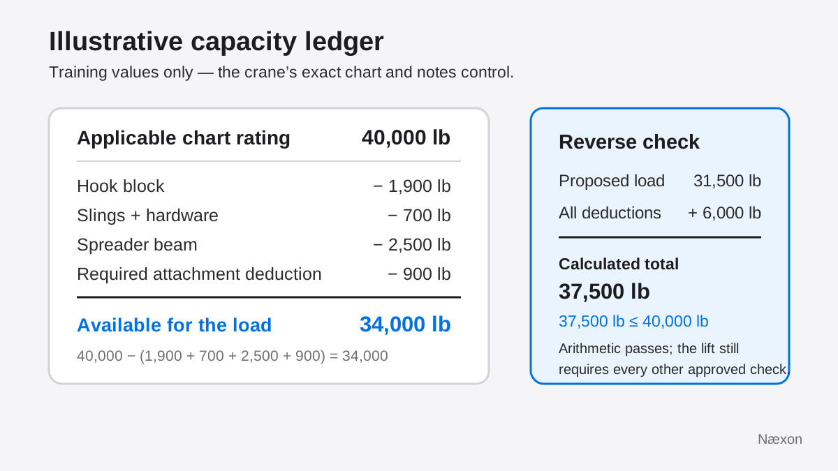
Independently check the arithmetic in the opposite direction. Add the proposed object and all deductions: 31,500 lb + 6,000 lb = 37,500 lb. That calculated total is less than the 40,000-pound chart rating, and the two methods agree. A reasonableness check also works: because the suspended equipment and attachment deduction total 6,000 pounds, the object cannot use the entire 40,000-pound rating.
A practical field sequence
- Freeze the configuration. Identify the exact crane, counterweight, boom, attachment, support, reeving, and operating area that will be used.
- Select the controlling chart condition. Verify the planned load radius and all chart notes. Recalculate if the pick path reaches a less favorable radius or configuration.
- List every suspended item. Trace the load path from boom point to object and record each block, line device, sling, connector, and below-the-hook device.
- Verify each weight. Use reliable documented values. Resolve an unknown or conflicting weight before the lift proceeds.
- Apply chart-note deductions. Record the source and exact condition for each attachment deduction. Do not invent or transfer values.
- Calculate both directions. Subtract deductions from the chart rating, then add the proposed object and deductions to check the total.
- Review the whole lift. Confirm that the arithmetic matches the approved lift plan and that capacity, ground support, rigging, load control, weather, communication, and exclusion-zone requirements are satisfied.
Incorrect approach versus correct approach
The incorrect approach compares the object weight directly with a chart number and calls the difference “extra capacity.” It fails because the crane is also carrying the hook block, rigging, and lifting devices. It can also miss a chart-required attachment deduction. A second incorrect approach subtracts every attachment value remembered from previous jobs, which can double-count equipment or apply the wrong crane's rules.
The correct approach uses one configuration-specific ledger. The crew identifies the chart cell, reads its notes, records the actual suspended components, verifies their weights, and applies only the deductions required by that crane's rating information. The result is traceable: another qualified person can see where every number came from.
Troubleshooting the calculation
If the crane display, lift plan, and hand calculation show different totals, stop before lifting. Confirm whether the display reports hook load, calculated suspended load, or a percentage of rated capacity. Electronic aids support the operator but do not replace the load chart or professional judgment.
If the hook block changes, the spreader is added late, the rigging arrangement changes, or an attachment is erected or removed, rebuild the ledger. A calculation tied to the previous configuration is no longer the calculation for the lift.
If the load weight is uncertain, verify it through a recognized source, calculation, or equally reliable means allowed by the procedure. Watch for retained liquid, packed material, temporary bracing, attached scaffolding, or components missing from the drawing. When the exact load, rigging, device, or deduction weight cannot be established, escalate to the lift director, competent or qualified person, engineer, or manufacturer as the governing procedure requires.
Common mistakes
Frequent errors include treating the table value as payload capacity, forgetting the lower rigging below a spreader, using the wrong hook-block weight, counting only sling legs and not shackles or master links, applying an attachment deduction from memory, and using a chart for the wrong boom or counterweight configuration.
Another mistake is rounding too early. Add the documented item weights using their stated precision, then round only as the controlling procedure allows. Never round downward to make a lift fit. Also remember that passing the arithmetic at one radius does not prove the entire pick path stays within capacity.
Field Rules
- Start with the correct serial-specific chart, configuration, radius, and notes.
- Count the object, hook block or ball, rigging hardware, and every below-the-hook device.
- Apply attachment deductions exactly as the manufacturer directs.
- Use documented weights; unknown weight means stop and resolve it.
- Check the arithmetic by both subtraction and addition.
- A positive remainder is not lift approval; every other lift-plan control still applies.
Knowledge Check
- A chart cell shows 28,000 pounds. The block weighs 1,300 pounds, rigging 450 pounds, and lifting beam 1,750 pounds. No other deduction applies. What weight remains available for the object?
- The object weighs 22,000 pounds and the chart value is 24,000 pounds, but the rigging and block weights are unknown. Can the operator conclude that the lift fits?
- A jib is installed but not carrying the load. What determines whether a deduction is required?
- After the plan is completed, the crew replaces the hook block with a different block. What is the first calculation response?
- Your reverse check gives a total suspended calculation of 37,500 pounds against a 40,000-pound chart value. What does that prove?
Answers
- 24,500 pounds. Total deductions are 1,300 + 450 + 1,750 = 3,500 pounds; 28,000 − 3,500 = 24,500 pounds.
- No. The missing suspended-item weights prevent a complete comparison. Verify them before proceeding.
- The exact manufacturer's chart and notes for that crane and configuration. An unused attachment may still require a deduction or a different chart.
- Replace the block weight in the ledger and recalculate. Also confirm reeving, chart notes, and the approved configuration remain correct.
- Only that the arithmetic total is below that chart value under the stated assumptions. It does not prove the radius, configuration, load weight, ground, weather, rigging, or lift plan is acceptable.
Practical Exercise
On paper, use an illustrative chart rating of 52,000 pounds. List a 2,200-pound block, 820 pounds of slings and hardware, a 3,400-pound lifting beam, and a 1,100-pound attachment deduction. Calculate the remaining allowable object weight, then test a proposed 43,500-pound object by reverse addition.
The expected deductions total 7,520 pounds, leaving 44,480 pounds for the object. The reverse check is 43,500 + 7,520 = 51,020 pounds. Your two calculations should agree, leaving an arithmetic difference of 980 pounds. Mark the sheet “training only” and list the missing real-lift inputs: exact crane chart, configuration, radius, verified weight sources, lift path, ground conditions, weather, rigging capacities, and approvals.
Related learning
Use crane load-radius fundamentals as the prerequisite for selecting the correct chart cell. Continue with the sling-length and rise method to calculate leg tension, then review wire-rope sling D/d ratio for bend geometry. For additional calculation practice, work through field formulas for riggers.